Table of Contents
Advertisement
Advertisement
Table of Contents
Troubleshooting

Summary of Contents for Smiths Medical SurgiVet Advisor WWV9230
- Page 1 Veterinary 3 Parameter Advisor® Vital Signs Monitor WW V9230 Operation Manual Patient ID NIBP MODE ALARMS TRENDS SETUP QUICKSET SUSPEND FREEZE MANUAL - English Catalog Number V1886R3 Version 0, February 2009 © 2009 Smiths Medical family of companies. All rights reserved.
-
Page 3: Table Of Contents
Table of Contents Table of Contents Warranty and Service Information ..................ix Proprietary Notice ....................................ix Warranty ........................................ix Limited Warranty .....................................ix Loaner Device (Domestic Sales Only) ............................ix Disclaimer of Warranties ................................x Conditions of Warranty ..................................x Limitation of Remedies ..................................x Warranty Procedure ..................................xi CE Notice ........................................xi Chapter 1: Introduction ....................... - Page 4 Table of Contents Chapter 4: Setting up the Monitor ..................4-1 Unpack the Monitor and Check the Shipment ..........................4-1 Quick Setup Instructions ...................................4-1 Detailed Setup Instructions ................................4-1 Select the Patient Type ..................................4-2 Change the Patient Type ..................................4-2 Add a New Patient ....................................4-3 Choose Which Patient Information to Display ........................4-3 Add a New Patient ..................................4-3 Add a Patient’s Name..................................4-4...
- Page 5 Table of Contents Chapter 6: Alarms ......................... 6-1 Parameter Alarms and System Alarms ............................6-1 Critical Failure Alarm (CFA) ................................6-1 High, Medium, and Low Priority Alarms ............................6-2 High Priority Alarms ..................................6-2 Medium Priority Alarms ................................6-2 Low Priority Alarms ..................................6-3 Controlling Alarms ....................................6-3 Turn off alarm detection................................6-3 Change alarm limits ..................................6-3 Adjust alarm volume ..................................6-3...
- Page 6 Table of Contents LEAD V OVERLOAD ................................... 7-12 ECG DISABLED .................................... 7-12 Verifying ECG Calibration ................................7-12 ECG Technical Data ................................... 7-13 Chapter 8: Oximetry ......................8-1 Using the Oximetry Parameter ................................8-1 Oximetry Measurement Capability ..............................8-1 Oximetry Warnings, Cautions, and Notes ............................8-2 Pulse Oximetry Theory of Operation .............................8-3 Attaching the Patient ..................................8-4 Application Guide ....................................8-5...
- Page 7 Table of Contents Canceling an NIBP Measurement ..............................9-8 Cleaning the NIBP Cuff ..................................9-9 NIBP Alarms ......................................9-10 NIBP Alarm Messages ................................9-11 Chapter 10: Operator’s Maintenance and Troubleshooting ...........10-1 Cleaning the Monitor’s Surfaces ..............................10-1 Long-term Storage .................................... 10-2 Operator’s Troubleshooting Chart ............................... 10-2 Chapter 11: Optional Supplies and Accessories ...............11-1 Ordering Information ..................................
- Page 8 Table of Contents Appendix A: ECG Technical Reference ................A-1 Tall T-Wave Rejection Capability..............................A-1 Heart Rate Averaging Method and Display Update Rate...................... A-1 Response Time of Heart Rate Meter to Change in Heart Rate .................... A-1 Display Aspect Ratio ................................... A-1 Audible Alarms .....................................
- Page 9 Table of Contents Advisor, SurgiVet and the Smiths design mark are trademarks of the Smiths Medical family of companies. The ® symbol indicates the trademark is registered in the U.S. Patent and Trademark Office and certain other countries. All other names and marks mentioned are the trade names, trademarks, or service marks of their respective owners.
- Page 10 Table of Contents This page is intentionally left blank. ® viii Veterinary 3 Parameter Advisor Operation Manual...
-
Page 11: Warranty And Service Information
Information contained in this document is copyrighted by Smiths Medical PM, Inc. and may not be duplicated in full or part by any person without prior written approval of Smiths Medical PM, Inc. Its purpose is to provide the user with adequately detailed documentation to efficiently install, operate, maintain and order spare parts for the device supplied. -
Page 12: Disclaimer Of Warranties
Warranty and Service Information Disclaimer of Warranties THE FOREGOING EXPRESS WARRANTY, AS CONDITIONED AND LIMITED, IS IN LIEU OF AND EXCLUDES ALL OTHER WARRANTIES WHETHER EXPRESS OR IMPLIED, BY OPERATION OF LAW OR OTHERWISE, INCLUDING BUT NOT LIMITED TO, ANY IMPLIED WARRANTIES OF MERCHANTABILITY OR FITNESS FOR A PARTICULAR PURPOSE. -
Page 13: Warranty Procedure
Box and inserts should be in original condition. If original shipping material in good condition is not available, it should be purchased from Smiths Medical PM, Inc. Damages occurring in transit in other than original shipping containers are the responsibility of the shipper. All costs incurred returning devices for repair are the responsibility of the shipper. - Page 14 Warranty and Service Information This page is intentionally left blank. ® Veterinary 3 Parameter Advisor Operation Manual...
-
Page 15: Chapter 1: Introduction
Chapter 1: Introduction Chapter 1: Introduction About This Manual This manual provides installation, operation, and maintenance instructions for the equipment supplied. This manual is intended for healthcare professionals trained in monitoring respiratory and cardiovascular activity. Conventions This manual uses visual clues to help convey messages. The following examples show the conventions used throughout the manual. -
Page 16: Definition Of Symbols
Chapter 1: Introduction Definition of Symbols SYMBOL DEFINITION Federal (U.S.A.) law restricts this device to sale by or on the order of a veterinarian. Defibrillator-proof type CF equipment Attention, see instructions for use. Dangerous voltage. Refer servicing to qualified service personnel. Output Loudspeaker Fuse... -
Page 17: General Warnings, Cautions, And Notes
If purchased before that date, they may also be sent for recycling if being replaced on a one- Separately for-one, like-for-like basis (this varies depending on the country). Recycling instructions to customers using Smiths Medical products are published on the internet at: http://www.smiths-medical.com/recycle Disposal (other countries) When disposing of this device, its batteries or any of its accessories, ensure that any negative impact on the environment is minimized. - Page 18 Chapter 1: Introduction WARNING! Equipment is protected against defibrillator discharge. Rate meters and displays may be temporarily affected during defibrillation, but will rapidly recover. WARNING! The vital signs monitor is suitable for use within the patient environment IEC 60950 approved equipment must be placed outside of the patient environment.
- Page 19 Chapter 1: Introduction WARNING! There is no defibrillator synchronization output on the monitor. Make no connections between the monitor and a defibrillator. WARNING! This monitor will not operate effectively on patients who are experiencing convulsions or tremors. WARNING! This monitor is not for home use. WARNING! The monitor should not be used adjacent to or stacked with other equipment.
-
Page 20: Ecg Warnings, Cautions, And Notes
Chapter 1: Introduction WARNING! Operation of this device may be adversely affected in the presence of computed tomography (CT) equipment. CAUTION! Do not allow water or any other liquid to be spilled onto the monitor. Unplug the AC power cord from the monitor before cleaning or disinfecting the monitor. CAUTION! This unit contains a lithium coin battery and a rechargeable alkaline battery. -
Page 21: Oximetry Warnings, Cautions, And Notes
Chapter 1: Introduction Oximetry Warnings, Cautions, and Notes WARNING! Prolonged use or the patient’s condition may require changing the sensor site periodically. Change the sensor site and check skin integrity, circulatory status, and correct alignment at least every 4 hours. ®... -
Page 22: Non-Invasive Blood Pressure Warnings, Cautions, And Notes
Non-invasive Blood Pressure Warnings, Cautions, and Notes WARNING! Blood pressure measurements may be inaccurate if cuffs and/or hoses other than those specified by Smiths Medical PM, Inc. are used. WARNING! Repeated use of STAT mode for periods longer than 15 minutes should be avoided to reduce the patient’s risk for soft tissue or nerve damage. -
Page 23: Chapter 2: Intended Use And General Information
Chapter 2: Intended Use and General Information Chapter 2: Intended Use and General Information Intended Use This vital signs monitor is intended to be used in special procedure labs and other areas of a veterinary hospital or clinic where veterinary monitoring systems are needed. The monitor package includes 3-lead or 5-lead electrocardiography (ECG), non-invasive blood pressure (NIBP), and pulse oximetry (SpO The device permits patient monitoring with adjustable alarm limits as well as visible and audible alarm signals. - Page 24 Chapter 2: Intended Use and General Information This page is intentionally left blank. ® Veterinary 3 Parameter Advisor Operation Manual...
-
Page 25: Chapter 3: Controls And Features
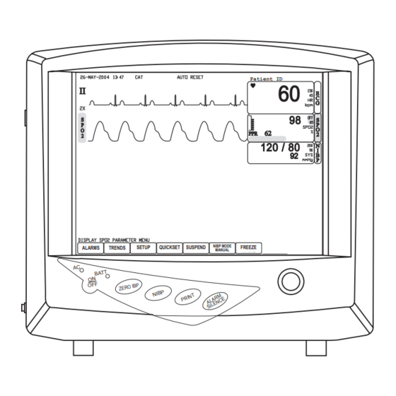
Chapter 3: Controls and Features Chapter 3: Controls and Features Indicators and Displays with Embedded Submenus The monitor has a large, high-resolution, high-contrast, color LCD display. It provides a continuous, real-time display of up to four waveforms. It also shows measured values, chronological data, measurement trends, and alarm limits. - Page 26 Chapter 3: Controls and Features DISPLAYS DESCRIPTION Alarm Status If the monitor detects that one or more of a patient’s parameter values are violated, ALARM will be displayed. If the patient’s parameter values are within the specified limits, the chosen alarm reset mode, either AUTO RESET or MANUAL RESET, will be displayed.
-
Page 27: Parameter Box
Chapter 3: Controls and Features Parameter Box Alarm Limits Measured Value Parameter Name Alarm Limit Descriptor Measurement Unit Figure 3.2: Parameter Box Parameter Box When you turn on a parameter, a box appears on the display containing the parameter or measurement name, the numeric values for the selected measurement, the high and low alarm limits, a descriptor for the alarm limits displayed, and the measurement unit. -
Page 28: Keys
Chapter 3: Controls and Features Keys Figure 3.3: Keys DESCRIPTION INSTRUCTION ON/OFF Press this key to turn on the monitor. To turn off the monitor, press the key and a message will be displayed indicating that if you continue to power down, some configuration data will be lost;... -
Page 29: Side Panel
Chapter 3: Controls and Features Side Panel The left side panel of your monitor contains all of the patient connector receptacles and the AC power receptacle. SPO2 TEMP 100-240AC 0.8A 50-60 Hz F 1.6A/250V WARNING: RISK OF FIRE REPLACE FUSE AS MARKED CAUTION NIBP Figure 3.4: Side Panel... -
Page 30: Back Panel
70105B1 REV. 3 ROTARY KNOB: TURN TO SELECT, PUSH IN TO 71012BXX ACTIVATE SELECTION MFD FOR Smiths Medical PM, Inc. Waukesha, WI. 53186 MADE IN U.S.A. Figure 3.5: Back Panel CONNECTOR DESCRIPTION INSTRUCTION Air Vents The monitor has air vents at the top of the back panel and on the bottom of the monitor. -
Page 31: Chapter 4: Setting Up The Monitor
Chapter 4: Setting up the Monitor Chapter 4: Setting up the Monitor Unpack the Monitor and Check the Shipment ® Before you begin setting up, carefully remove the Advisor Vital Signs Monitor and its accessories from the shipping carton. Save the packing materials in case the monitor must be shipped or stored. Compare the packing list with the supplies and equipment you received to make sure the shipment is complete. -
Page 32: Select The Patient Type
Chapter 4: Setting up the Monitor Select the Patient Type The patient type indicator is located on the upper portion of the display. The default patient type is DOG. When you change the patient type: • The alarm limits will be reset to default settings (unless STATIC LIMITS mode is on). •... -
Page 33: Add A New Patient
Chapter 4: Setting up the Monitor Add a New Patient The patient identity indicator is located in the upper right corner of the display. You can choose which patient information to display: just the bed, the bed and the patient’s name, or the bed and the patient ID. While specific patient identification information is expected to change, the bed or room to which the monitor is assigned may remain the same. -
Page 34: Add A Patient's Name
Chapter 4: Setting up the Monitor Add a Patient’s Name Turn the rotary knob on the monitor to move the cursor. Highlight the BED: PATIENT field in the upper right corner of the display. The field may be blank. Push the knob to access the patient identification submenu in the lower left corner of the display. -
Page 35: Parameter Options
Chapter 4: Setting up the Monitor Parameter Options The PARAMETER OPTIONS submenu provides setup options associated with specific monitoring parameters. You can choose 3-lead or 5-lead ECG processing. You can turn on or off some of the installed parameters. And, you can change the measurement unit that describes the parameter. -
Page 36: Change The Units Of Measurement
Chapter 4: Setting up the Monitor Change the Units of Measurement Units of measurement can be changed for NIBP. The selected units of measurement will remain in the monitor’s memory until changed, even if the monitor is turned off. Turn the rotary knob on the monitor to move the cursor. On the main menu at the bottom of the display, highlight SETUP and push the knob to select. -
Page 37: Parameter Colors
Chapter 4: Setting up the Monitor Parameter Colors You can change the color of the text in each displayed parameter box and its corresponding waveform. Available colors are green, blue, cyan, magenta, white, orange, pink, lime (light green), purple, sky (light blue), and brown. Red, black, and yellow are reserved system colors and cannot be assigned. -
Page 38: Service Menu
Chapter 4: Setting up the Monitor Service Menu Access to the service menu is by authorized password only. Refer to Chapter 12: Service Menu for use of this option. Time and Date If necessary, set the time and date on the display. The time and date indicator is located in the upper left corner of the display. -
Page 39: Chapter 5: Monitoring The Patient
Chapter 5: Monitoring the Patient Chapter 5: Monitoring the Patient Follow the steps in Chapter 4: Setting Up the Monitor; the remainder of this chapter assumes that the monitor is properly installed and set up. General Monitoring Instructions Regardless of the parameters or measured values you want to monitor, follow these steps when you are ready to attach a patient. -
Page 40: Adjust The Parameter Box Settings
Chapter 5: Monitoring the Patient Adjust the Parameter Box Settings • Turn the rotary knob on the monitor to move the cursor. Highlight the parameter box name and push the knob to access the parameter menu in the lower left corner of the display. The settings available for the selected parameter will be displayed. -
Page 41: Use These Features As Needed
Chapter 5: Monitoring the Patient Turn the rotary knob to move the cursor back to the name of the measured value and push to select. Highlight MENU in the alarm limit box and push the knob to select. Highlight MAIN MENU and push the knob to select. Use these Features as Needed Responding to an Alarm When a numeric measured value matches or exceeds the high or low limit set for that parameter, an alarm... -
Page 42: Disabling Alarms
Chapter 5: Monitoring the Patient Disabling Alarms To turn off the alarm detection capability for a single parameter: Turn the rotary knob on the monitor to move the cursor. Highlight the parameter box name and push the knob to access the parameter menu in the lower left corner of the display. Highlight [MEASURED VALUE] ALARMS and push the knob to select. -
Page 43: Quickset Alarm Limits
Chapter 5: Monitoring the Patient QUICKSET Alarm Limits You can quickly adjust the high and low alarm limits using the QUICKSET feature. You may choose to reset all the alarm limits, or just the alarm limits for a measured value that has matched or exceeded a high or low limit and generated an alarm. - Page 44 Chapter 5: Monitoring the Patient The newly reset alarm limit will be displayed in the parameter box. • If a current measured value is not available, no changes will be made with QUICKSET. • If a high or low alarm limit is set to OFF, no changes will be made with QUICKSET. •...
-
Page 45: Resetting Alarm Limits Using The Quickset Feature
Chapter 5: Monitoring the Patient Resetting Alarm Limits using the QUICKSET Feature To reset all high and low alarm limits for the current measured values using the QUICKSET feature: Turn the rotary knob on the monitor to move the cursor. On the main menu at the bottom of the display, highlight QUICKSET and push the knob to select. -
Page 46: Nibp Mode
Chapter 5: Monitoring the Patient NIBP Mode Non-invasive blood pressure (NIBP) measurements can be made in automatic, manual, or STAT modes. In the automatic mode, the monitor will measure the patient’s NIBP periodically, according to the interval you select. In the manual mode, the monitor will measure the patient’s NIBP only when you press the NIBP key ( ). -
Page 47: Freeze Mode
Chapter 5: Monitoring the Patient Freeze Mode Use this feature to temporarily hold or freeze all current waveforms, even those that are not displayed. Monitoring does not stop; you can still view the current measured values in the parameter boxes. When you freeze the waveforms, you may not adjust any waveform settings. -
Page 48: Erasing Stored Trend Data
Chapter 5: Monitoring the Patient To view the stored tabular trend data in selected time increments: Turn the rotary knob on the monitor to move the cursor. On the main menu at the bottom of the display, highlight TRENDS and push the knob to select. Highlight TABULAR VITAL SIGNS and push the knob to access the vital signs box. -
Page 49: Erasing Nibp History
Chapter 5: Monitoring the Patient Erasing NIBP History To erase the stored NIBP history from the monitor’s memory: Turn the rotary knob on the monitor to move the cursor. On the main menu at the bottom of the display, highlight TRENDS and push the knob to select. Highlight NIPB HISTORY and push the knob to access the NIBP history box. - Page 50 Chapter 5: Monitoring the Patient This page is intentionally left blank. ® 5-12 Veterinary 3 Parameter Advisor Operation Manual...
-
Page 51: Chapter 6: Alarms
Chapter 6: Alarms Chapter 6: Alarms Follow the steps in Chapter 4: Setting Up the Monitor; the remainder of this chapter assumes that the monitor is properly installed and set up. Parameter Alarms and System Alarms A parameter alarm occurs when there is a malfunction with any of the sensors or connections, or when a numeric measured value matches or exceeds the high or low limit set for that parameter. -
Page 52: High, Medium, And Low Priority Alarms
Chapter 6: Alarms High, Medium, and Low Priority Alarms Alarms are categorized as high priority, medium priority, or low priority. High Priority Alarms A high priority alarm sound consists of two bursts of five single tones over a four-second interval. The sequence is repeated every ten seconds. -
Page 53: Low Priority Alarms
Chapter 6: Alarms Low Priority Alarms A low priority alarm sound consists of a single burst of two single tones that repeat every 20 seconds. ALARM will appear, yellow and steady, in the alarm status line and the alarm message in the parameter box will be displayed. PARAMETER LOW PRIORITY ALARM RA, LA, LL, or V fail... -
Page 54: Stop Alarms Automatically Or Manually
Chapter 6: Alarms To change the alarm volume: Turn the rotary knob on the monitor to move the cursor. On the main menu at the bottom of the display, highlight ALARMS and push the knob to select. Highlight ALARM VOLUME and push the knob to select. Turn the rotary knob to increase or decrease the volume to the desired level and push the knob to select. -
Page 55: Chapter 7: Ecg
Chapter 7: ECG Chapter 7: ECG ECG Measurement Capability ® The 3 Parameter Advisor Vital Signs Monitor provides continuous three-lead and five-lead ECG processing with standard lead selections and filtering from electrocautery discharge. The heart rate measured value (HR) and primary lead messages are displayed in the ECG parameter box, and a waveform for the primary ECG lead is continuously displayed. -
Page 56: Theory Of Operation
Chapter 7: ECG Theory of Operation Electrical currents influenced by the cardiac impulse flow through the body tissue around the heart. Three or five electrodes, placed on the skin on opposite sides of the heart, transmit the electrical potentials to circuitry in the monitor. - Page 57 Chapter 7: ECG To attach the ECG leads to the patient, position three or five alligator clips in the standard configuration. WARNING! Electrodes of dissimilar metals should not be used. Figure 7.3: Position the ECG Leads Be sure that the leads are in the correct ECG cable position. The ECG leads and patient cable connector are color-coded according to the AAMI standard for ECG leads.
-
Page 58: Choosing The Waveform Settings
Chapter 7: ECG Choosing the Waveform Settings Use the ECG waveform menu options to choose the primary ECG lead and adjust the settings for the size and speed of the ECG waveform. Access the Waveform Menu The ECG waveform menu is accessible from any ECG waveform label or from the ECG parameter box name. Parameter Box Waveform Label... -
Page 59: Change The Primary Ecg Lead
Chapter 7: ECG Change the Primary ECG Lead Waveform 1 is dedicated to the primary ECG lead. For both three-lead and five-lead processing, lead II is the default primary lead. You can designate any other lead to be the primary using the ECG waveform menu. The selected primary lead will be displayed in the waveform label. -
Page 60: Choose The Waveform Size
Chapter 7: ECG Choose the Waveform Size You can choose the size of the ECG waveforms on the display. The selected size (0.5X, 1X, 2X, or 4X) will appear in the waveform label. The default size is times one (1X). Figure 7.5: ECG Waveform Size Waveform Size To change the size of the ECG waveform:... -
Page 61: Use Waveforms 2-4 To Display Ecg
Chapter 7: ECG Use Waveforms 2-4 to Display ECG Waveforms 2, 3, and 4 can be used to display ECG waveforms as well. For three-lead processing, you can cascade or continue the waveform of the primary ECG lead into each successive waveform area. For five-lead processing, you can designate a second lead to display as an ECG waveform or you can cascade the primary lead from Waveform 1. -
Page 62: Adjusting The Settings In The Parameter Box
Chapter 7: ECG Adjusting the Settings in the Parameter Box Turn Alarm Detection On or Off You can turn on or off the alarm detection capability for the heart rate value. If HR ALARMS is on, an alarm will be issued when the high or low alarm limit is violated. If you turn HR ALARMS off and the high or low alarm limit is violated, an alarm will not be issued. -
Page 63: Adjust The Volume Of The Heartbeat Beep Tone
Chapter 7: ECG Adjust the Volume of the Heartbeat Beep Tone You can set the monitor to issue a beep tone with each detected heartbeat. You can control the volume of the beep tone, or turn it off. If the SPO reading is valid, the pitch of the beep tone will vary depending on changes in oxygen saturation. -
Page 64: Ecg Alarm Messages
Chapter 7: ECG ECG Alarm Messages The messages are listed below in order of their display priority. NOTE! If more than one ECG alarm condition occurs simultaneously and the alarm reset mode is set to MANUAL, the highest-priority message is displayed in the ECG parameter box. However, if an ASYSTOLE alarm is issued and then another, lower priority ECG alarm occurs, the ASYSTOLE message and the other alarm message will alternately be displayed in the parameter box. -
Page 65: Ra Fail
Chapter 7: ECG RA FAIL This message is displayed in the ECG parameter box when either the RA lead fails, or the RA and V leads fail during 5-lead processing. During an RA FAIL alarm, lead III is displayed in Waveform 1. All other ECG waveforms are erased. -
Page 66: Lead Ii Overload
Figure 7.8: Verify ECG Calibration You will need: ® • 3 Parameter Advisor Vital Signs Monitor • Smiths Medical PM, Inc. 1606 SpO /ECG Patient Simulator ® • SurgiVet 3311 Oximetry Cable • 3 or 5 lead set (V3110 or V3406) To verify that the ECG parameter is calibrated: Disconnect all cables and sensors from the monitor. -
Page 67: Ecg Technical Data
Chapter 7: ECG Select 3-LEAD ECG processing: On the main menu at the bottom of the display, highlight SETUP and push the knob to select. Highlight PARAMETER OPTIONS and push the knob to access the parameter options submenu. Highlight ECG LEADS PROCESSING and push the knob to select. Highlight 3-lead and push the knob to select. - Page 68 Chapter 7: ECG This page is intentionally left blank ® 7-14 Veterinary 3 Parameter Advisor Operation Manual...
-
Page 69: Chapter 8: Oximetry
Chapter 8: Oximetry Chapter 8: Oximetry Using the Oximetry Parameter This chapter includes information specific to the Oximetry parameter. Refer to chapters 4-7 for general step-by- step monitoring instructions. The remainder of this chapter assumes that the monitor is properly installed and set up. -
Page 70: Oximetry Warnings, Cautions, And Notes
Chapter 8: Oximetry Oximetry Warnings, Cautions, and Notes WARNING! Prolonged use or the patient’s condition may require changing the sensor site periodically. Change the sensor site and check skin integrity, circulatory status, and correct alignment at least every 4 hours. ®... -
Page 71: Pulse Oximetry Theory Of Operation
Chapter 8: Oximetry Pulse Oximetry Theory of Operation The pulse oximeter determines %SpO and pulse rate by passing two wavelengths of low intensity light, one red and one infrared, through body tissue to a photodetector. Information about wavelength range can be especially useful to clinicians. -
Page 72: Attaching The Patient
Chapter 8: Oximetry Attaching the Patient WARNING! Prolonged use or the patient’s condition may require changing the sensor site periodically. Change the sensor site and check skin integrity, circulatory status, and correct alignment at least every 4 hours. ® WARNING! When attaching sensors with Microfoam tape, do not stretch the tape or attach the tape too tightly. -
Page 73: Application Guide
Chapter 8: Oximetry If necessary, connect the sensor to the patient cable. Connect the patient cable to the monitor. Align the pins on the patient cable with the monitor’s SpO receptacle and push the connector firmly into the receptacle. Connect the •... -
Page 74: Mini Clip (V3078)
Chapter 8: Oximetry Mini Clip (V3078) The Mini Clip is similar to the Universal ‘Y’ Sensor, but less than a quarter of the size of the lingual clip. The smaller clip is effective on small breeds and especially on smaller cats. The clip will work on a cat’s ear, tongue, and toe webbing. -
Page 75: Checking The Oximeter's Performance
Chapter 8: Oximetry Checking the Oximeter’s Performance Pulse oximeters do not require user calibration. If checking the function of the device is desired, an optional Oximetry Patient Simulator (SMPM catalog number 1606) is available as an accessory. The simulator attaches to the oximeter in place of the sensor or oximetry cable. -
Page 76: Choose The Waveform Speed
Chapter 8: Oximetry Choose the Waveform Speed You can choose the speed at which the SpO waveform is displayed. To change the speed of the SpO waveform: On the SpO 2 waveform menu, highlight SPEED and push the knob to select. Highlight the desired size of the waveform (6.25, 12.5, 25, or 50 mm/second) and push the knob to select. -
Page 77: Choose The Averaging Period For The Oximetry Parameter
Chapter 8: Oximetry Choose the Averaging Period for the Oximetry Parameter NOTE! SpO averaging to the number of pulse beats over which the SpO value is averaged; pulse averaging is the number of seconds over which the pulse value is averaged. The measured values for oximetry (%SpO and PPR) can be determined by averaging the sensor readings over a selected number of beats or seconds. -
Page 78: Spo Alarms
Chapter 8: Oximetry Alarms An SpO alarm will be issued when the numeric measured value for SpO matches or exceeds the alarm limits set for %SpO (or PPR if SpO is the selected heart rate source), when the monitor loses a pulse, or when there is a malfunction with the sensor. -
Page 79: Oximetry Alarm Messages
Chapter 8: Oximetry Oximetry Alarm Messages The following messages can be displayed in the SpO parameter box: ALARM MESSAGE POSSIBLE CAUSE CORRECTIVE ACTION CHECK SENSOR Be sure the sensor is properly This message is displayed in the SpO positioned on the patient. parameter box when the monitor is unable to detect that the sensor is Be sure that the patient cable is... - Page 80 Chapter 8: Oximetry This page is intentionally left blank. ® 8-12 Veterinary 3 Parameter Advisor Operation Manual...
-
Page 81: Chapter 9: Non-Invasive Blood Pressure
Chapter 9: Non-invasive Blood Pressure Chapter 9: Non-invasive Blood Pressure Using the NIBP Parameter This chapter includes information specific to the non-invasive blood pressure (NIBP) parameter. Refer to chapters 4-6 for general step-by-step monitoring instructions. The remainder of this chapter assumes that the monitor is properly installed and set up. -
Page 82: Non-Invasive Blood Pressure Warnings, Cautions, And Notes
Non-invasive Blood Pressure Warnings, Cautions, and Notes WARNING! Blood pressure measurements may be inaccurate if cuffs and/or hoses other than those specified by Smiths Medical PM, Inc. are used. WARNING! Verify cuff size is correct for the selected patient mode on the monitor. -
Page 83: Nibp Theory Of Operation
31543B4) Cuff Warranty Cuffs carry a six-month warranty, pending evaluation by Smiths Medical PM, Inc. Technical Services. Cuffs that are contaminated, have liquid in them, have been misused/abused, or are older than six months will not be covered under the warranty. - Page 84 Chapter 9: Non-invasive Blood Pressure Figure 9.2: Attach the Cuff WARNING! Verify cuff size is correct for the selected patient mode on the monitor. Attach the cuff to the patient. Squeeze all the air out of the cuff. ® Place the cuff on a limb at the same level as the heart. The SurgiVet logo should be facing up, away from the patient.
- Page 85 Chapter 9: Non-invasive Blood Pressure Figure 9.4: Connect the Cuff to the Supply Hose Be sure the patient type (CAT, DOG, or HORSE) is appropriate for the patient. See Select the patient type in Chapter 4: Setting Up the Monitor for instructions for setting the patient type. If necessary, add the patient information to the monitor.
-
Page 86: Adjusting The Settings In The Parameter Box
Chapter 9: Non-invasive Blood Pressure Adjusting the Settings in the Parameter Box Turn Alarm Detection On or Off You can turn on or off the alarm detection capability for each of the NIBP measured values (SYS, DIA, and MAP). You can also choose which alarm limits to display in the parameter box (SYS, DIA, or MAP). If SYS ALARMS is on, an alarm will be issued when the high or low alarm limit for systolic pressure is violated, regardless of which set of alarm limits is displayed. -
Page 87: Choose The Inflation Pressure
Chapter 9: Non-invasive Blood Pressure Choose the Inflation Pressure You can change the cuff inflation pressure before any measurement. If you change the pressure, the monitor will use the new value for the next NIBP measurement. The default settings are 200 mmHg for the cat mode, 150 mmHg for the dog mode, and 100 mmHg for the horse mode. -
Page 88: Auto Nibp Mode
Chapter 9: Non-invasive Blood Pressure AUTO NIBP Mode If you selected AUTO as the NIBP MODE, the first measurement will begin after the interval time has elapsed. The time remaining (00:00:00) will flash for several seconds indicating that an NIBP measurement is going to begin. NOTE! If you suspend patient monitoring (by selecting SUSPEND from the main menu) while AUTO is the selected NIBP mode, the monitor will return to the default mode (MANUAL) when you resume monitoring. -
Page 89: Cleaning The Nibp Cuff
Chapter 9: Non-invasive Blood Pressure Cleaning the NIBP Cuff ® Place the Cuff Cap (SurgiVet part number 31545B1) on the end of the cuff hose. NOTE! Failure to place the cuff cap on the hose will allow water to enter the bladder. This will cause the cuff to malfunction and will damage the monitor. -
Page 90: Nibp Alarms
Chapter 9: Non-invasive Blood Pressure NIBP Alarms An NIBP alarm will be issued when the numeric measured value for pressure matches or exceeds the alarm limits set for systolic, diastolic or mean arterial pressure or when there is a malfunction with the blood pressure cuff. See Set the Alarm Limits in Chapter 5: Monitoring the Patient for instructions for setting high and low alarm limits. -
Page 91: Nibp Alarm Messages
Chapter 9: Non-invasive Blood Pressure NIBP Alarm Messages The following messages can be displayed in the NIBP parameter box: ALARM MESSAGE POSSIBLE CAUSE CORRECTIVE ACTION COM ERROR This message is displayed in the Turn the monitor off and back on NIBP parameter box when the again. - Page 92 Chapter 9: Non-invasive Blood Pressure ALARM MESSAGE POSSIBLE CAUSE CORRECTIVE ACTION NIBP CAL ERROR This message is displayed in the Contact your authorized repair NIBP parameter box when there center for help. is a malfunction during the NIBP calibration procedure. This is a low priority alarm.
-
Page 93: Chapter 10: Operator's Maintenance And Troubleshooting
Vital Signs Monitor Service Manual (Smiths Medical PM, Inc. part number V1887R) also contains the circuit diagrams, parts lists, and descriptions required for carrying out repairs and disposing of batteries. The Service Manual is available on request from Smiths Medical PM, Inc. or your local agent. MAINTENANCE ITEM... -
Page 94: Long-Term Storage
(fuse type: 5 x 20 mm fast-acting center. 1.6 A/250 V). The display on the monitor does The display backlight is defective. Contact the Smiths Medical PM, not light. Inc. service department. CHECK SENSOR is displayed in the Reposition the sensor on the... - Page 95 Change the sensor or contact the Either the SpO sensor or the Smiths Medical PM, Inc. service extension cable is defective. department. The ECG leads and electrodes are The ECG parameter is turned off. Turn on ECG MONITOR using the connected, but no ECG waveform ECG parameter menu.
- Page 96 Chapter 10: Operator’s Maintenance and Troubleshooting This page is intentionally left blank. ® 10-4 Veterinary 3 Parameter Advisor Operation Manual...
-
Page 97: Chapter 11: Optional Supplies And Accessories
NIBP Purple Cuff Supply Hose, 1.8m (6 ft.) each Ordering Information For ordering information, contact your local distributor or the Smiths Medical PM, Inc. customer service department at the address or phone number below: Smiths Medical PM, Inc. Phone: (262) 513-8500... - Page 98 Chapter 11: Optional Supplies and Accessories This page is intentionally left blank. ® 11-2 Veterinary 3 Parameter Advisor Operation Manual...
-
Page 99: Chapter 12: Service Menu
Chapter 12: Service Menu Chapter 12: Service Menu The service menu is password protected and contains the following options: CHANGE MONITOR VERIFY NIBP STATIC LIMITS SERIAL UPDATE: PASSWORD DEFAULTS CALIBRATION PURCHASED ECG ATTENDED MODE ALLOWED TEST CFA ALARM: DEMO MODE: OPTIONS To access the service menu: Turn the rotary knob on the monitor to move the cursor. -
Page 100: Setting Default Values For The Monitor
Chapter 12: Service Menu Setting Default Values for the Monitor Default values are settings you can choose that will apply to your monitor each time you turn it on. You can set up your monitor to operate using the default values you choose for alarm limits, ECG filter, language, and alarm silence operation. -
Page 101: Set The Ecg Filter Level
Chapter 12: Service Menu To restore the factory default alarm limits for each parameter: See Using the Static Limits Feature in this section for details about how turning on or off the static limits feature affects default alarm limits. Select the desired patient type (CAT, DOG, or HORSE). The patient type indicator is located on the upper portion of the display. -
Page 102: Select The Alarm Audio Silence Operation
Chapter 12: Service Menu Select the Alarm Audio Silence Operation You can choose how the alarm silence key ( ) will function. If you select TEMPORARY ONLY: • When you press the alarm silence key ( ), an audible alarm will be temporarily silenced for two minutes. AUDIO PAUSED will be displayed on the upper right side of the display. -
Page 103: Changing The Service Menu Password
Chapter 12: Service Menu Changing the Service Menu Password The service menu is password protected. You can access the service menu only by using a password. Authorized personnel may change the password. To change the password: On the service menu, highlight CHANGE PASSWORD and push the knob to select. Turn the rotary knob to access the password box and push the knob to select the first character field. -
Page 104: Using The Factory Service Menu
Chapter 12: Service Menu When the static limits feature is on and you change high and low alarm limits in the alarm limits box, or the default alarm limits box, or you restore the factory default alarm limits, these limits will be applied immediately. If you change the patient type or turn off the monitor and then turn it on again, the changes in the alarm limits will be retained in the alarm limit box and the default alarm limit box. -
Page 105: Auto-Detectable Parameters
Chapter 12: Service Menu Auto-Detectable Parameters You can turn on or off the auto-detectable parameters, such as oximetry (SpO ), using the demo options menu, available on the SETUP menu. To turn on or off auto-detectable parameters: Turn the rotary knob on the monitor to move the cursor. Highlight SETUP and push the knob to access the setup menu. - Page 106 Chapter 12: Service Menu This page is intentionally left blank. ® 12-8 Veterinary 3 Parameter Advisor Operation Manual...
-
Page 107: Chapter 13: Specifications
Chapter 13: Specifications Chapter 13: Specifications Display 10.4-inch diagonal high-resolution TFT (Thin Film Transistor) Active Matrix LCD Resolution: 640 X 480 pixels Indicators LEDs: AC Power ( green) with power plug icon Battery Charge ( green) with battery icon (NOT USED) Alarm Volume 45dBA to 85 dBA at 1 meter distance (adjustable) Keys/User Controls... -
Page 108: Ecg
Chapter 13: Specifications Heart Rate Range: 20-350 bpm Heart Rate Accuracy: ±2 bpm or ±2% (whichever is greater) QRS Detection Range: 0.5 to 5 mV Pace Pulse Detection: ±2 mV to ±700 mV amplitude Detection Duration: 0.1 – 2.0 ms Alarm Ranges Heart Rate: High: 20-350 bpm and OFF Low: 20-350 bpm and OFF... -
Page 109: Nibp
Chapter 13: Specifications NIBP Blood Pressure Measuring Method of Measurement: Oscillometric with step-down deflation Range: Systolic: 40 to 265 mmHg Mean Arterial: 27 to 222 mmHg Diastolic: 20 to 200 mmHg Pulse: 25 to 300 bpm NIBP Accuracy: Algorithm based on human algorithm that meets or exceeds accuracy requirements of ANSI / AAMI SP10:1992 and 2002 standards for non-invasive blood pressure using the oscillometric method. -
Page 110: Design Standards
Chapter 13: Specifications Design Standards Safety: EN60601-1 EN60601-1-1 UL2601 CSA Standard C22.2 No. 601.1 EMC: EN60601-1-2:2001 FDA Reviewer’s Guidance for Resp Devices, Nov. 93 DEVICE: AAMI EC13, IEC 60601-2-27 ECG AAMI SP10, IEC 60601-2-30 NIBP EN865 SpO EN475 Alarms IEC 60601-2-49 Multifunction Patient Monitoring Equipment Equipment Classification Type of Protection: Class 1 &... -
Page 111: Appendix A: Ecg Technical Reference
Appendix A: ECG Technical Reference Appendix A: ECG Technical Reference Tall T-Wave Rejection Capability With a standard 1 mV p-p QRS having a T-wave amplitude of 0 to 1.2 mV (0 to 120% of R-wave height), the displayed heart rate remains correct. Heart Rate Averaging Method and Display Update Rate The rate digit display is updated every second. -
Page 112: Audible Alarm Silencing
Appendix A: ECG Technical Reference Audible Alarm Silencing Audible alarms may be silenced in three ways. To manually re-enable the alarms, press the alarm silence key ( on the front of the monitor. An audible alarm may be temporarily silenced for two minutes. To temporarily silence an alarm, press the alarm silence key ( ). -
Page 113: Appendix B: Alarm Limit Defaults
Appendix B: Alarm Limit Defaults Appendix B: Alarm Limit Defaults Heart Rate ECG LIMIT DEFAULTS Horse HEART RATE HIGH LIMIT HEART RATE LOW LIMIT QUICKSET HIGH VALUE QUICKSET LOW VALUE No Change No Change No Change Oximetry LIMIT DEFAULTS Horse HIGH LIMIT LOW LIMIT QUICKSET HIGH VALUE... - Page 114 Appendix B: Alarm Limit Defaults This page is intentionally left blank. ® Veterinary 3 Parameter Advisor Operation Manual...
-
Page 115: Appendix C: Iec 60601-1-2 Requirements, 2Nd Edition, 2001
Appendix C: IEC 60601-1-2 Requirements, 2nd Edition, 2001 Appendix C: IEC 60601-1-2 Requirements, 2nd Edition, 2001 GUIDANCE AND MANUFACTURER’S DECLARATION – ELECTROMAGNETIC EMISSIONS ® The Advisor Vital Signs Monitor is intended for use in the electromagnetic environment specified below. The ®... - Page 116 Appendix C: IEC 60601-1-2 Requirements, 2nd Edition, 2001 GUIDANCE AND MANUFACTURER’S DECLARATION – ELECTROMAGNETIC IMMUNITY ® The Advisor Vital Signs Monitor is intended for use in the electromagnetic environment specified below. The ® customer or user of the Advisor Vital Signs Monitor should assure that it is used in such an environment. ELECTROMAGNETIC IMMUNITY TEST IEC 60601 TEST LEVEL...
- Page 117 Appendix C: IEC 60601-1-2 Requirements, 2nd Edition, 2001 GUIDANCE AND MANUFACTURER’S DECLARATION – ELECTROMAGNETIC IMMUNITY ® The Advisor Vital Signs Monitor is intended for use in the electromagnetic environment specified below. The ® customer or user of the Advisor Vital Signs Monitor should assure that it is used in such an environment. COMPLIANCE ELECTROMAGNETIC IMMUNITY TEST...
- Page 118 Appendix C: IEC 60601-1-2 Requirements, 2nd Edition, 2001 GUIDANCE AND MANUFACTURER’S DECLARATION – ELECTROMAGNETIC IMMUNITY ® The Advisor Vital Signs Monitor is intended for use in an electromagnetic environment in which radiated ® RF disturbances are controlled. The customer or user of the Advisor Vital Signs Monitor can help prevent electromagnetic interference by maintaining a minimum distance between portable and mobile RF ®...
-
Page 119: Appendix D: Revision History
Appendix D: Revision History Appendix D: Revision History REVISION DATE COMMENT Rev. 0 2009-02 • Created Rev 0 ® Veterinary 3 Parameter Advisor Operation Manual... - Page 120 Appendix D: Revision History This page is intentionally left blank. ® Veterinary 3 Parameter Advisor Operation Manual...
- Page 122 Authorized Representative (as defined by the Medical Device Directive): Smiths Medical International, Ltd. Phone: (44) 1923 246434 Colonial Way, Watford, Hertfordshire, Fax: (44) 1923 240273 WD24 4LG, UK Manufactured By Smiths Medical PM, Inc. N7W22025 Johnson Drive Waukesha, WI 53186-1856 USA...
Need help?
Do you have a question about the SurgiVet Advisor WWV9230 and is the answer not in the manual?
Questions and answers
The CO2 box is showing an occlusion error. I checked all components, all appear to be fine. How do I resolve this?
on the right side of the monitor, there is a filter for Co2 and a filter with what looks like to be sodalime/sodasorb in it. Do these need to be replaced and how often? What are these filters called for reorder?