
Related Manuals for Mowin LIWIN L25

Summary of Contents for Mowin LIWIN L25
- Page 1 Manuale di istruzioni per l’uso ISTRUCTION MANUAL MODE D’EMPLOI BEDIENUNGSANLEITUNG MANUAL DE INSTRUCCIONES Инструкция по монтажу...
-
Page 2: General Information
1. GENERAL INFORMATION 1.1 Introduction to this manual Please read carefully and follow the instructions detailed in this manual. Keep the manual for use and future maintenance. Pay attention to the configuration of the DIP-switches, to the data concerning the performance (see “Technical Data”) and to the installation instructions. Improper use or incorrect operation, fitting or assembly can damage the system as well as cause injury to people and damage to property. The assembling instructions are available on the official web site http://www.comunello.com/mowin 2. SAFETY This installation manual is written exclusively for competent professional personnel. The installation, electrical connections and adjustments must be carried out conforming to good practice and according to the regulations in force. Incorrect installation can cause a potential hazard. The packing materials (plastic, polystyrene, etc.) must not be allowed to pollute the environment, but must be disposed of correctly, and must not be left within the reach of children since they can cause possible hazards. Before starting installation, check the product is complete and undamaged. If the power cable is damaged, it must be replaced by the manufacturer or his technical support or a similarly qualified person in order to avoid any risks. Do not install the product in an explosive environment or atmosphere: the presence of flammable gas or fumes is a serious health and safety hazard. Before installing the drive mechanism, put in place all the structural modifications relating to safety measures and to the protection or segregation of all the zones involving hazards of crushing, shearing, entrapment and of general hazard. Check that all the existing structure has the necessary requirements of strength and stability. The manufacturer of the drive mechanism is not responsible for failing to conform to good practice in the construction of the windows to be opened, as well as any distortion which could occur during use. Put up the notices laid down by current regulations to identify hazardous areas. Ensure that the electrical supply is not a temporary one, but has the required electrical boxes, and in case of doubt or lack of (definite) information, also install: - suitable isolating transformers; - thermal magnetic cut-outs suitable to voltage requirements; - surge arrester. - Page 3 Check that on the supply side of the electrical plant there is a suitable differential residual current circuit breaker and overload protection. When required to do so, connect to an efficient earthing/ground system fitted according to the safety regulations in force in the country where the actuator is being installed. Before carrying out any operation (installation, maintenance or repair), isolate the electrical supply before working on the equipment. To ensure complete isolation from the supply current, installation is recommended of a double-pole switch of the approved type. The low-voltage 24 Vdc actuators must be supplied by suitable power supplies (NOT TRANSFORMERS) of an approved Class II type (double safety insulation) having an output voltage of 24 Vdc -15% to +20% (or from 20.4 Vdc min. to 28.8 Vdc max.) When using the 24 Vdc version, the cable must have a suitable cross-section, calculated based on the distance between the power supply and the actuator, so as not to have a voltage drop or loss. Cross section of cables Max length of the cable 1,50 mm...
-
Page 4: Technical Data
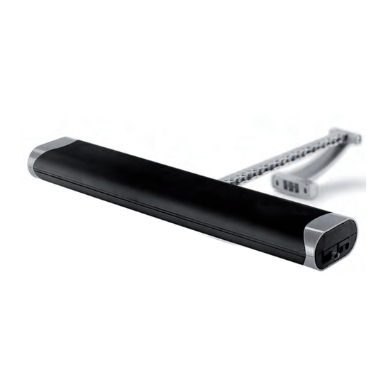
3. TECHNICAL DATA 3.1 Table of technical data and mark The CE mark certifies that the actuator conforms to the essential health and safety requirements laid down by European product directives. The CE mark can be identified by the relevant adhesive label applied to the outside of the product, on which are shown some of the data shown in the following table: Liwin 2W-Net Liwin 2W-Net R Liwin Liwin 3W-Net Liwin R Liwin 3W-Net R Liwin 4W-Net Liwin 4W-Net R Model L35 230Vac ML35S140Hy00* ML35Sx40Hy00** ML35R140Hy00* ML35Rx40Hy00** Model L35 24Vdc ML35S140Ly00* ML35Sx40Ly00** Model L25 230Vac ML25S138Hy00* Power supply ac voltage 230 Vac 230 Vac 230 Vac 230 Vac Power supply dc voltage 24 Vdc 24 Vdc Frequency of ac voltage 50 Hz 50 Hz 50 Hz... - Page 5 4. ACTUATOR 4.1 Types of power supply The Liwin series of actuators is available in various models and colours in two electrical supply versions: • 230 Vac - can be supplied with mains power 230 Vac (50 Hz) (with a tolerance of ±10%), with a three-core supply cable: BLUE, neutral common; BLACK, open phase; BROWN, closed phase. • 24 Vdc - can be supplied with a voltage of 24 Vdc with a two-core supply cable: BLUE, connected to the + (positive) closed; BROWN, connected to the + (positive) open. 4.2 Calculation of the force necessary The calculation is made without considering the loads due to atmospheric agents. Key to symbols F = Force required to open in N (Newton) P = Weight of the window (only moveable part) in kg (kilogrammes) C = Opening travel of actuator in cm (centimetres) H = Height of the openable part of the window in cm (centimetres) Bottom-hung inward opening Top-hung outward opening Horizontal skylight F = [(P / 2 ) x (C/H)] x 9.8 F = [(P / 2 ) x (C/H)] x 9.8 F = (P / 2) x 9.8 4.3 Pack and tools required for assembling the actuator The actuator is packed individually in a cardboard box. Each pack contains: electric actuator, 230 Vac 50 Hz or 24 Vdc, with electric supply cable, support brackets, fixing bracket for top-hung window, fixing bracket for bottom-hung window, drilling template and instruction manual.
-
Page 6: Installation
5. INSTALLATION With bottom-hung windows, there is a danger of potential injury resulting from the window accidentally falling. It is OBLIGATORY to fit limiting arms (of the Series 1276 type), or an alternative safety system, of a suitable size to prevent the window from accidentally falling down. Top-hung outward opening window: Overall dimensions and fixing holes 54.4 54.4 Filo Serramento Filo Serramento Bottom-hung inward opening window: Overall dimensions and fixing holes 106.3 106.3 Filo Serramento... - Page 7 Bottom-hung inward opening window: Top-hung outward opening window: CAUTION If the window is of the bottom-hung type, check that the limiting arms have been fitted to prevent the window from accidentally falling down. Bottom-hung inward opening window: With a pencil, Top-hung outward opening window: With a pencil, mark mark the mid-point “X”...
- Page 8 Bottom-hung inward opening window: Bottom-hung inward opening window: Top-hung outward opening window: Top-hung outward opening window: Pre-fit the support brackets to the frame using the alignment template. Stick the alignment template lable on the frame. ta n te r ó n / fe tr e n ê / fe in d / ra d re tr a F in fi n tr a...
- Page 9 Bottom-hung inward opening window: Top-hung outward opening window: Insert the side fulcrum pin into the support bracket Move the actuator towards the window frame in order to insert the (opposite) side fulcrum pin into the support bracket Rotate the actuator, as shown in the following drawing, to fix it firmly.
- Page 10 Bottom-hung inward opening window: Top-hung outward opening window: Rotate the actuator so as to allow the window to shut. Rotate the actuator in the opposite direction so that the end of the Rotate the actuator in the opposite direction so that the end of the chain can be inserted correctly inside the bottom-hung window fixing. chain can be inserted correctly inside the top-hung window fixing. Join the chain to the fixing by inserting the relevant Join the chain to the fixing by inserting the relevant locking pin. locking pin. Clip the cover in place.
- Page 11 Bottom-hung inward opening window: Top-hung outward opening window: Removal of end cap and rubber cover. Positioning the DIP-switch...
- Page 12 Select the stroke distance required by following the setting of the DIP-switches according to the scheme below. Note: each DIP-switch has three possible positions. Liwin 350N Dip-switch 1 Dip-switch 2 Stroke Dip-switch 1 Dip-switch 2 Stroke Middle Middle Middle Middle Botton Botton Botton Botton Middle Middle Middle Middle Botton Botton...
- Page 13 5.2 Electrical connection Wire in the apparatus according to the electrical supply required by the actuator (see label on product), following the table below. 230 Vac supply 24 Vdc supply Blue Neutral / Common Blue Positivo Black Phase / Open Brown Negativo Brown Phase /Closed White Data (2/3/4 W-Net actuators) White Data (2/3/4 W-Net actuators) Yellow Data (2/3/4 W-Net actuators)
- Page 14 5.3 Operating test Press the control button and close the window, checking that: A. The window is completely closed. If it is not, check that the gap between the window and the frame is bigger than or equal to 0 mm. If necessary, insert spacers so as to obtain the correct gap. B. The chain is perfectly vertical to the window frame. If necessary adjust the fixing bracket by using the screws and slots. Having reached the correct closing position, press the control button and open the window in order to check that the actuator runs freely over the full travel set up. Having achieved the required opening run, press the control button again to close the window. Once the window has completely closed, check that the screws, supports and fixings are tightened correctly, and that the seals are sufficiently compressed. Bottom-hung inward opening window: Top-hung outward opening window: Insert the rubber DIP-switch cover and close the end cap Installation completed CAREFUL!! - after installation the 4 covers must be perfectly closed.
- Page 15 ATTENTION! Before operating the actuator, please make sure that the product has been fixed at the right position 6. MAINTENANCE, EMERGENCY ACTION & CLEANING If it becomes necessary to manually disconnect the window from the actuator due to: a power failure, mechanical breakdown, maintenance, or cleaning the exterior of the window, follow the step sequence described on Page 11 in reverse order. BEWARE OF THE DANGER of the window falling; as the window is free to fall, as it is no longer held up by the chain.
-
Page 16: Protection Of The Environment
7. PROTECTION OF THE ENVIRONMENT Some parts inside the actuator are not recyclable (plastic materials and electronic parts) and cannot be considered normal refuse. They must be disposed of correctly. In case of doubt, consult the relevant refuse disposal body. 8. FAQ (frequently asked questions) Question Cause Remedy Check the electrical cut-out or safety switch is “On”. No voltage supply A cable may not be connected. With volta- The actuator is not ge supplied | Check the actuator voltage operating corresponds to voltage supply detected. Check the actuator voltage corresponds With voltage supplied to voltage supply detected Check that according to the table on... - Page 17 9. GUARANTEE Fratelli Comunello SpA provides a warranty for thirty-six months for the correct functioning of the actuators from the date of manufacture, provided that the performance specifications indicated in the product instruction manuals are respected. Free of charge repair and replacement of components that are found to be faulty according to the indisputable judgment of the company’s technical staff shall be guaranteed at the sole discretion of Fratelli Comunello Spa, and so excluding any claim for damages made by others. Warranty material shall be returned to Fratelli Comunello S.p.a. headquarters carriage paid and will then be shipped to the customer carriage unpaid. The material found to be faulty and returned to Fratelli Comunello S.p.a. shall remain property of the Seller. Any cost resulting from any work needed to repair the defect or to replace the material shall be charged to the Buyer. No compensation shall be allowed for the period of device inactivity. Work under warranty does not prolong the warranty period. The defect of the product shall be reported by the Buyer within 8 (eight) days from its discovery or from the date of delivery of the goods, under penalty of invalidation of the warranty. Such claim shall be notified in writing. Warranty does not cover: Any product defect or damage that may have been incurred during transport; any defect or damage arising from any fault and/or from neglect, inadequacy and misuse of the electrical wiring in the Buyer’s property; any defect or damage caused by any repairs carried out by non authorised personnel or by incorrect use/ installation (with reference to this, system maintenance is recommended every 6 months) or if not original spare parts are used; any defect caused by chemicals or atmospheric conditions. The warranty does not cover any cost neither for consumable materials nor for alleged defects or convenient surveys. Product Features Fratelli Comunello SpA products are subjected to continue changes and improvements; their technical features and image may therefore change without previous notice.
Need help?
Do you have a question about the LIWIN L25 and is the answer not in the manual?
Questions and answers