
Related Manuals for Kyongbo Electric GDR-M02

Summary of Contents for Kyongbo Electric GDR-M02
- Page 1 Digital Motor Protection Relay (GDR-M02) User's Manual (V1.00) Digital Motor Protection Relay User's Manual TYPE : GDR-M02 2010. 04. 12 Version 1.00 Kyongbo Electric Co., Ltd. KyongBo Electric Co.,Ltd 1 / 76...
- Page 2 Digital Motor Protection Relay (GDR-M02) User's Manual (V1.00) Safety Precautions This document is for the safety of the user, and to prevent property damage. Be sure to read the user manual carefully, and use the product accordingly. The user manual must be kept in a place where it can be easily seen by the product user.
- Page 3 Digital Motor Protection Relay (GDR-M02) User's Manual (V1.00) WARNING • Do not perform any wiring work while the power is on or the product is in operation. It may cause an electric shock. • Must verify the status of the grounding connection before starting the operation.
- Page 4 Digital Motor Protection Relay (GDR-M02) User's Manual (V1.00) CAUTION • Apply the rated power to the power source terminal. Otherwise, it may cause a damage to the product or a fire. • Follow the rated load on the input and output connections.
-
Page 5: Table Of Contents
Digital Motor Protection Relay (GDR-M02) User's Manual (V1.00) Table of Contents 1. General Features ················································································································· 10 2. Technical Data ······················································································································ 12 2.1 Voltage, Current Input ································································································· 12 2.2 Rated Control Source Voltage ···················································································· 12 2.3 Rated Frequency ··········································································································· 12 2.4 Case ································································································································ 12 2.5 Time OverCurrent Element ·························································································... - Page 6 Digital Motor Protection Relay (GDR-M02) User's Manual (V1.00) 4. Subsidiary Function ·············································································································· 29 4.1 Metering ··························································································································· 29 4.2 Communication ················································································································ 29 4.2.1 RS-232C Communication ························································································ 29 4.2.2 RS-485C Communication ························································································ 30 4.3 Self Diagnosis Function ································································································· 31 4.4 Fault Recording Function ······························································································ 31 5.
- Page 7 Digital Motor Protection Relay (GDR-M02) User's Manual (V1.00) Order of Table 【Table 2.1】 Input Voltage ································································································· 12 【Table 2.2】 Rated Control Power ···················································································· 12 【Table 2.3】 Case ················································································································ 12 【Table 2.4】 Time OverCurrent Element ·········································································· 13 【Table 2.5】 Instantaneous OverCurrent Element ···························································· 13 【Table 2.6】...
- Page 8 Digital Motor Protection Relay (GDR-M02) User's Manual (V1.00) Order of Figures 【Figure 3.1】 INST. OCR(IOCR) Logic Diagram ····························································· 21 【Figure 3.2】 Time OCR(TOCR) Logic Diagram ····························································· 22 【Figure 3.3】 INST. OCGR(IOCGR) Logic Diagram ······················································· 23 【Figure 3.4】 Time OCGR(TOCGR) Logic Diagram ························································ 23 【Figure 3.5】...
- Page 9 Digital Motor Protection Relay (GDR-M02) User's Manual (V1.00) Order of Diagram Appended 1. Dimensioned Drawings Unit : mm ····························································· 62 Appended 2. Internal Block Diagram ··················································································· 63 Appended 3. External Connection Diagram ········································································· 63 Appended 4. Over current, Ground Over Current Element NI Characteristic Curve ········ 64 Appended 5.
-
Page 10: General Features
Digital Motor Protection Relay (GDR-M02) User's Manual (V1.00) 1. General Features This Relay contains Relay elements of 50/51×3, 50/51N×1, 47×1, 46×1, 59×3, 27×3 at the same time, and is a Digital arithmetic relay designed and manufactured properly for the protection when fault occurred such as overcurrent, ground overcurrent, overvoltage, undervoltage, negative-sequence current, reverse phase etc. - Page 11 Digital Motor Protection Relay (GDR-M02) User's Manual (V1.00) ▣ Various communications supported - Communication Methods : RS-232C, RS-485C (SCADA communications) - Supported Protocol : MODBUS ▣ Enhanced EMC / EMI performance ▣ Applied Standard : Korea Electrical Manufacturers' Cooperative Standard (KEMC1120) KyongBo Electric Co.,Ltd...
-
Page 12: Technical Data
Digital Motor Protection Relay (GDR-M02) User's Manual (V1.00) 2. Technical Data 2.1 Voltage, Current Input 【Table 2.1】 Input Current Rated Voltage AC 110V Rated Current AC 5A Voltage 1.15 times rated voltage / 3 hours Overload Endurance 2 times rated current / 3 hours... -
Page 13: Time Overcurrent Element
Digital Motor Protection Relay (GDR-M02) User's Manual (V1.00) 2.5 Time OverCurrent Element 【Table 2.4】 Time Over Current Element Operation Value 2.0 ~ 12.5A (0.1A Step) Inverse Time Inverse Time (KEPCO Type) Very Inverse Time Very Inverse Time 0.1 ~ 10.0... -
Page 14: Time Ground Overcurrent Element
Digital Motor Protection Relay (GDR-M02) User's Manual (V1.00) 2.7 Time Ground Overcurrent 【Table 2.6】 Time Ground Over Current Element Operation Value 0.2 ~ 2.5A (0.1A Step) Inverse Time Inverse Time (KEPCO Type) Very Inverse Time Very Inverse Time 0.1 ~ 10.0... -
Page 15: Overvoltage Element
Digital Motor Protection Relay (GDR-M02) User's Manual (V1.00) 2.9 Over Voltage Element 【Table 2.8】 Over Votlage Element Operation Value 65 ~ 170V (1V Step) Inverse Time 0.1 ~ 10.0 (0.1 Step) Operation Time Characteristics Definite Time 0.04 ~ 60.00Sec (0.01Sec Step) Release Delay Time 0.00 ~ 60.00Sec (0.01Sec Step) -
Page 16: Negative-Sequence Current Element
Digital Motor Protection Relay (GDR-M02) User's Manual (V1.00) 2.12 Negative-Sequence Current Element 【Table 2.11】 Negative-Sequence Current Element Operation Value Negative-Sequence 30 ~ 70% (1% step) Operation Time Definite 0.04 ~ 60.00Sec (0.01Sec Step) Characteristics Time Release Delay Time 0.00 ~ 60.00Sec (0.01Sec Step) -
Page 17: Insulation Test
Digital Motor Protection Relay (GDR-M02) User's Manual (V1.00) 2.14 Insulation Test 【Table 2.13】 Insulation Electric Circuit to 10MΩ Ground Insulation Between Electric DC 500V IEC60255-5 Resistance Circuits 5MΩ Between Electric Circuit Connections Electric Circuit Bundle to Ground Commercial 50/60Hz, Between Electric... -
Page 18: Mechanical Test
Digital Motor Protection Relay (GDR-M02) User's Manual (V1.00) 2.15 Mechanical Test 【Table 2.14】 Mechanical Test 10 ~ 150Hz, 0.5G, Front/Back, Left/Right, Vibration Response Up/Down 1 time Vibration 10 ~ 150Hz, 1G, Front/Back, Left/Right, Vibration Endurance Up/Down 20 times 5G, Front/Back, Left/Right, Up/Down... -
Page 19: Temperature, Humidity Test
Digital Motor Protection Relay (GDR-M02) User's Manual (V1.00) 2.17 Temperature, Humidity Test 【Table 2.16】 Temperature, Humidity Test Operation Assurance -10℃ ~ +55℃ Temperature Range Recovery Assurance -20℃ ~ +60℃ Relative Humidity Daily Average 30% ~ 90% 2.18 EMI : ElectroMagnetic Interference 【Table 2.17】... -
Page 20: Protection Characteristics
3.1 OverCurrent Function This relay contains the Instantaneous Time characteristic and Time Characteristics of 9 to be used for overcurrent and short circuit protection. GDR-M02 marks the instantaneous element as INST.OCR(IOCR), and the time over current element as Time OCR(TOCR), time characteristics curve type is as follow 【Table 3.1】... -
Page 21: Table 3.1】 Time Curve Characteristic
Digital Motor Protection Relay (GDR-M02) User's Manual (V1.00) 【Table 3.1】 Time Curve Characteristic Feature Value Time Characteristic Reference 0.14 0.02 0.11 0.02 0.42 KEPCO Type 13.5 39.85 1.95 1.084 KEPCO Type KLNI 0.11 KEPCO Type KLVI KEPCO Type When setting the relay, selecting the time characteristic curve will decide the K, L, C values in the above table. -
Page 22: Figure 3.2】 Time Ocr(Tocr) Logic Diagram
Digital Motor Protection Relay (GDR-M02) User's Manual (V1.00) 【Figure 3.2】 Time OCR(TOCR) Logic Diagram KyongBo Electric Co.,Ltd 22 / 76... -
Page 23: Ground Overcurrent Function
Digital Motor Protection Relay (GDR-M02) User's Manual (V1.00) 3.2 Ground Over Current Function It has the same fundamental and characteristic with 3-Phase Over Current relay function, and the only differences are that it receives the ground current signal input and the setting range is smaller than 3-phase Over Current. -
Page 24: Overvoltage Function
Digital Motor Protection Relay (GDR-M02) User's Manual (V1.00) 3.3 Over Voltage Function This relay has Inverse Time and Definite Time characteristic for Over Voltage element. NI characteristic relate voltage and time equation that if voltage magnitude is lager, operation time is short. -
Page 25: Undervoltage Function
Digital Motor Protection Relay (GDR-M02) User's Manual (V1.00) 【Figure 3.6】OVR Logic Diagram ( 3 Phases ) 3.4 Under Voltage Function This relay has Inverse Time and Definite Time characteristic for Under Voltage element. Operated Under Voltage element has many release mode, at first that voltage is higher than setting, second that user push reset key. -
Page 26: Figure 3.7】 Uvr Logic Diagram ( 1 Phase )
Digital Motor Protection Relay (GDR-M02) User's Manual (V1.00) Logic Diagram for under voltage element operation is as follows. 【Figure 3.7】UVR Logic Diagram ( 1 Phase ) 【Figure 3.8】UVR Logic Diagram ( 3 Phases ) KyongBo Electric Co.,Ltd 26 / 76... -
Page 27: Negative-Sequence Current Function
Digital Motor Protection Relay (GDR-M02) User's Manual (V1.00) 3.5 Negative-Sequence Current Function This relay has Definition Time for Negative Sequence current element. When motor come phase open according to inner problem or the other factor, motor stop rotate or continuous rotate. At this time, rotator of motor flow large current and motor has demage. -
Page 28: Reverse Phase Function
Digital Motor Protection Relay (GDR-M02) User's Manual (V1.00) 3.6 Reverse Phase Function This relay has Definite Time for Reverse Phase element. This relay protective reverse phase input, that is element prevent backlashing. Relay compare 3phase angle dissimilarity, if relay detect angle exchange, operate DT (0.04 ~ 60.00 Sec). -
Page 29: Subsidiary Function
Digital Motor Protection Relay (GDR-M02) User's Manual (V1.00) 4. Subsidiary Function 4.1 Metering This relay measure voltage, current, angle, Unbalanced current. 【Table 4.1】 Measurement function Section Feature ● Voltage RMS and angle metering. ● Primary line-to-line voltage that input voltage Vab, Vbc, Vca exchange PT ratio. -
Page 30: Rs-485C Communication
Digital Motor Protection Relay (GDR-M02) User's Manual (V1.00) 【Figure 4.1】 RS-232C Circuit 【Figure 4.2】 RS-232C Connect 【Table 4.2】 Communication Method Communication Method ● RS-232 / RS-485 Protocol ● MODBUS Spe c i f i cati on Distance ● 1.2km Line ●... -
Page 31: Self Diagnosis Function
Digital Motor Protection Relay (GDR-M02) User's Manual (V1.00) 【Figure 4.3】 RS-485C Connect Diagram 4.3 Self Diagnosis Function Self-diagnosis function keep back non-operation and mal-operation though observation at all time. If this function detect error, error LED turn on and self-diagnosis unit display FAIL. -
Page 32: Display Panel Construction
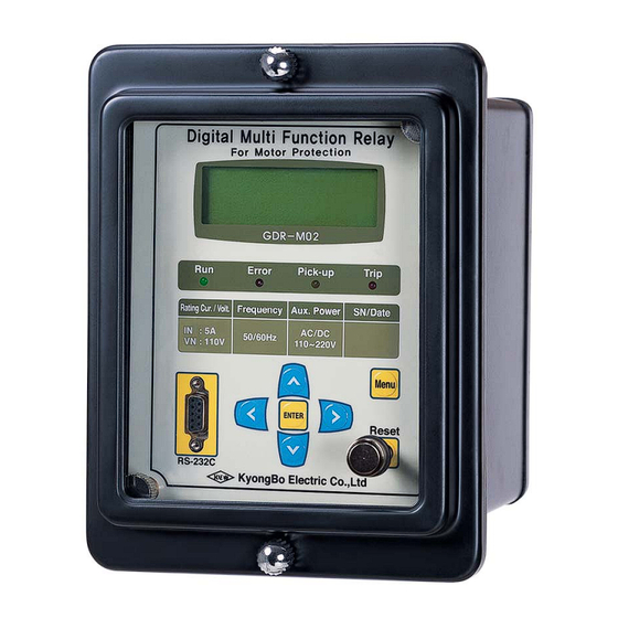
Digital Motor Protection Relay (GDR-M02) User's Manual (V1.00) 5. Display Panel Construction 5.1 Front-side Display Panel Structure Front-side and control panel have 20×4 LCD, 4 LED, 7 Keypad and RS-232C connector like【Figure 5.14】. When setting change, must input password, so other person don't change setting, and protective element run during relay control and setting change through LCD display. -
Page 33: Key Pad & Communication Connector
Digital Motor Protection Relay (GDR-M02) User's Manual (V1.00) 5.2 Key Pad & Communication Connector 【Table 5.1】 Key Pad & Communication Connector Direction Key Setting change and move to other menu use. ENTER ( ) Key Key use confirm, when menu or setting confirm. -
Page 34: Display & Setting Modes
Digital Motor Protection Relay (GDR-M02) User's Manual (V1.00) 6. Display & Setting Modes 6.1 Key Control & LCD Construction 6.1.1 LCD Main Display, Backlight On/Off LCD display main after supplied control power. G D R - M 0 2 V 1 . 0... -
Page 35: Setting Modes
Digital Motor Protection Relay (GDR-M02) User's Manual (V1.00) 【Figure 6.1】 Menu Tree 6.1.5 Setting Modes To right operate of this relay setting value match the power system. Setting and display elements of 7 are Measurement, Protection, Self-Diagnosis, RS-485 Comm., System Config, Recorder, Test. - Page 36 Digital Motor Protection Relay (GDR-M02) User's Manual (V1.00) - 〉 S e t i n g 1 . M e a s u r e m e n t 2 . P r o t e c t i o n 3 .
-
Page 37: Measurement Screen
Digital Motor Protection Relay (GDR-M02) User's Manual (V1.00) 6.1.6 Measurement Display Measurement display indicate measuring voltage and current. Vab, Vbc, Vca mean line-to-line voltage, Ia, Ib, Ic mean phase current, In mean zero-sequence current, Iu mean unbalanced current ratio and indicate magnitude and angle. -
Page 38: Table 6.1】 Time Ocr Menu
Digital Motor Protection Relay (GDR-M02) User's Manual (V1.00) T i m e O C R - 〉 1 . C U R V E 2 . P I C K - U P 5 . 0 A 3 . T - D I A L 1 0 . -
Page 39: Table 6.2】 Inst. Ocr Menu
Digital Motor Protection Relay (GDR-M02) User's Manual (V1.00) 【Table 6.2】 INST. OCR Menu Basis Unit Range Step Reference Value OFF, Inst, Definite MODE OFF, INST, DT time Setting PickUp 10 ~ 90A Inst. Pickup value DT-Time 0.04 ~ 60.00Sec 0.01Sec 0.04Sec... -
Page 40: Table 6.4】 Inst. Ocgr Menu
Digital Motor Protection Relay (GDR-M02) User's Manual (V1.00) - 〉 I N S T O C G R 1 . M O D E 2 . P I C K - U P 3 . D T - T I M E 0 . -
Page 41: Table 6.5】 Ovr Menu
Digital Motor Protection Relay (GDR-M02) User's Manual (V1.00) 【Table 6.5】 OVR Menu Basis Unit Range Step Reference Value OFF, Inverse, Definite CURVE OFF, NI, DT Time Setting Single Phase / PHASE 1, 3 PHASE 1 PHASE 3 Phase Setting PICK-UP... -
Page 42: Table 6.6】 Uvr Menu
Digital Motor Protection Relay (GDR-M02) User's Manual (V1.00) 【Table 6.6】 UVR Menu Basis Unit Range Step Reference Value OFF, Inverse, Definite CURVE OFF, NI, DT Time Setting Single Phase / PHASE 1, 3 PHASE 1 PHASE 3 Phase Setting PICK-UP... -
Page 43: Self-Diagnosis Screen
Digital Motor Protection Relay (GDR-M02) User's Manual (V1.00) 6.1.7.8 Protection ▶ RPR Setting This is to set Reverse Phase Element. In Protection, select ( ) 8. RPR, display follow. R P R S e t - 〉 1 . M O D E 2 . -
Page 44: Rs-485 Comm. Setting
Digital Motor Protection Relay (GDR-M02) User's Manual (V1.00) 6.1.9 RS-485 Comm. Setting For setting of communication unit set Baudrate, Slave Addr. In setting, select 4. RS-485 Comm., Comm. setting display follow. R S - 4 8 5 C o m m . -
Page 45: System Config. Setting
Digital Motor Protection Relay (GDR-M02) User's Manual (V1.00) - 〉 P o w e r S y s t e m 1 . F R E Q 6 0 H z * 2 . P _ C T _ R A T : 5 : 5 3 . -
Page 46: Table 6.10】 T/S Connection Menus
Digital Motor Protection Relay (GDR-M02) User's Manual (V1.00) If you set T/S output you want, to use Key and move to ( * ) indicator at wish menu. System Config. ▶ T/S Output ▶ T/S 1 Setting T/S number menu set connecting type, return method and delay time of 4 contact output. - Page 47 Digital Motor Protection Relay (GDR-M02) User's Manual (V1.00) System Config. ▶ T/S Output ▶ T/S 1 ▶ 2. RST Setting This menu set to return method of contact output. This relay has two method of Self Mode and Manual Mode.
-
Page 48: Recorder
Digital Motor Protection Relay (GDR-M02) User's Manual (V1.00) - 〉 P a s s w o r d N e w P a s s w o r d : * * * * C f m . P a s s w o r d... -
Page 49: Test
Digital Motor Protection Relay (GDR-M02) User's Manual (V1.00) If you want to escape Display Fault, press Key. Exchange upper display. 6.1.11.2 Recorder ▶ 2.Clear Fault Unit This menu can delete saving fault recording. In Recorder, select 2.Clear Fault, Clear Fault display follow. - Page 50 Digital Motor Protection Relay (GDR-M02) User's Manual (V1.00) In upper display for Display Test, press Key so, exchange from “No” to “Yes” and press ENTER ( ) Key, if so, move to Test menu after TEST of LCD and all LED flicker 3time.
-
Page 51: Table 6.11】 Setting Menus
Digital Motor Protection Relay (GDR-M02) User's Manual (V1.00) 【Table 6.11】 Setting Menus Vab∠θº, Vbc∠θº, Vca∠θº, 1.Measurements Ia∠θº, Ib∠θº, Ic∠θº, In∠θº, Iu(%) OFF, NI, VI, EI, LI, DT, 1.Curve KVI, KNI,, KLVI, KLNI 1.Time 2.PickUp 2.0~12.5A (0.1A Step) 3.Time Dial 0.1~10.0 (0.1Step) 4.DT_Time... - Page 52 Digital Motor Protection Relay (GDR-M02) User's Manual (V1.00) 3.Self-Diagnosis Power, CPU Watchdog, Memory, Setting 1.Protocol MODBUS 4.RS-485 300, 600, 1200, 2400, 2.Baudrate Comm. 4800, 9600, 19200 (bps) 3.Slave Addr 1 ~ 254 1.FREQ 50Hz or 60Hz 2.P_CT_RAT 5 ~ 10000 : 5 (5 Step) 1.Power...
-
Page 53: Pc Software
When relay change setting, repeat changing work, however, if you use GDR-M02, it work once, and save working data, so, if you do same working, it so open save file therefore so easy. Connected all working data is saved and again open. -
Page 54: Program Menu
Digital Motor Protection Relay (GDR-M02) User's Manual (V1.00) 7.1 Program Menu Basic menu of GDR-M02 is composed Communication Setting menu, File input and output menu, Relay relate Setting menu, and detail refer to【Table 7.1】. 【Table 7.1】 GDR-M02 Program Menus ● Program Menu Select Com. -
Page 55: Communication Port Configuration
Digital Motor Protection Relay (GDR-M02) User's Manual (V1.00) 7.2 Communication Port Configuration This function use to select Com-port in 15port that don't used because of another equipment. Also, RS-232C communication protocol is MODBUS, so PC software use with RS-485. 【Figure 7.2】 Communication Port Setting 【Table 7.2】... -
Page 56: Setting Value Change Screen
Digital Motor Protection Relay (GDR-M02) User's Manual (V1.00) 7.3 Setting Change Display When execute GDR-M02 Setting Tool, come out Setting, Status, Report contents display. In here, if click Relay → PC ( ) button, confirm system composition and saving data of relay, and, in setting display, if click PC → Relay ( ) button, send to relay PC setting. -
Page 57: Status
Description of this item equal to relay menu composition display, so refer to “6. Display and Setting Mode”. 【Figure 7.4】 GDR-M02 Status Measurement unit of GDR-M02 is kV, kA, mA, %. Click Read button, relay shows last fault recording. Click RST button, it operate remote Indicator Reset like relay Reset ( ) Key. -
Page 58: Report
Digital Motor Protection Relay (GDR-M02) User's Manual (V1.00) 7.3.3 Report save relay information( Relay Information, Setting Data, System Configuration, Fault Record ) txt file throw connected relay and PC. 【Figure 7.5】 GDR-M02 Report KyongBo Electric Co.,Ltd 58 / 76... -
Page 59: Help
Digital Motor Protection Relay (GDR-M02) User's Manual (V1.00) 7.4 Help This menu is known description of Setting Tool, A/S support, internet homepage, E-mail address, address, telephon number etc. 【Figure 7.6】Help KyongBo Electric Co.,Ltd 59 / 76... -
Page 60: Appendix 1. Setting Value At Product Shipping
Digital Motor Protection Relay (GDR-M02) User's Manual (V1.00) Appendix 1. Setting Value at Product Shipping 1. Curve 2. PickUp 1. Time 3. Time Dial 4. DT_Time 1. Mode 2. INST. 2. PickUp 50 A 3. DT_Time 0.04 Sec 1. Curve 2. - Page 61 Digital Motor Protection Relay (GDR-M02) User's Manual (V1.00) 1. Baudrate 19200 bps 4. RS-485 comm. 2. Slave Addr 1. FREQ 2. P_CT_RAT 5 : 5 1. Power System 3. G_CT_RAT 5 : 5 4. P_PT_RAT 1 : 1 1. CON...
-
Page 62: Appended 1. Dimensioned Drawings Unit : Mm
Digital Motor Protection Relay (GDR-M02) User's Manual (V1.00) Appended 1. Dimensioned Drawings Unit : mm KyongBo Electric Co.,Ltd 62 / 76... -
Page 63: Appended 2. Internal Block Diagram
Digital Motor Protection Relay (GDR-M02) User's Manual (V1.00) Appended 2. Internal Block Diagram Appended 3. External Connection Diagram KyongBo Electric Co.,Ltd 63 / 76... -
Page 64: Appended 4. Over Current, Ground Over Current Element Ni Characteristic Curve
Digital Motor Protection Relay (GDR-M02) User's Manual (V1.00) Appended 4. Over Cu r rent, G round Over Cu r rent Element NI Cha r acteristic Cu rve KyongBo Electric Co.,Ltd 64 / 76... -
Page 65: Appended 5. Over Current, Ground Over Current Element Vi Characteristic Curve
Digital Motor Protection Relay (GDR-M02) User's Manual (V1.00) Appended 5. Over Cu r rent, G round Over Cu r rent Element VI Cha r acteristic Cu rve KyongBo Electric Co.,Ltd 65 / 76... -
Page 66: Appended 6. Over Current, Ground Over Current Element Ei Characteristic Curve
Digital Motor Protection Relay (GDR-M02) User's Manual (V1.00) Appended 6. Over Cu r rent, G round Over Cu r rent Element EI Cha r acteristic Cu rve KyongBo Electric Co.,Ltd 66 / 76... -
Page 67: Appended 7. Over Current, Ground Over Current Element Li Characteristic Curve
Digital Motor Protection Relay (GDR-M02) User's Manual (V1.00) Appended 7. Over Cu r rent, G round Over Cu r rent Element LI Cha r acteristic Cu rve KyongBo Electric Co.,Ltd 67 / 76... -
Page 68: Appended 8. Over Current, Ground Over Current Element Kni(Kepco Type) Characteristic Curve
Digital Motor Protection Relay (GDR-M02) User's Manual (V1.00) Appended 8. Over Current, Ground Over Current Element KNI( ) Characteristic Curve KEPCO Type KyongBo Electric Co.,Ltd 68 / 76... -
Page 69: Appended 9. Over Current, Ground Over Current Element Kvi(Kepco Type) Characteristic Curve
Digital Motor Protection Relay (GDR-M02) User's Manual (V1.00) Appended 9. Over Current, Ground Over Current Element KVI( ) Characteristic Curve KEPCO Type KyongBo Electric Co.,Ltd 69 / 76... -
Page 70: Appended 10. Over Current, Ground Over Current Element Klni(Kepco Type) Characteristic Curve
Digital Motor Protection Relay (GDR-M02) User's Manual (V1.00) Appended 10. Over Current, Ground Over Current Element KLNI( ) Characteristic Curve KEPCO Type KyongBo Electric Co.,Ltd 70 / 76... -
Page 71: Appended 11. Over Current, Ground Over Current Element Klvi(Kepco Type) Characteristic Curve
Digital Motor Protection Relay (GDR-M02) User's Manual (V1.00) Appended 11. Over Current, Ground Over Current Element KLVI( ) Characteristic Curve KEPCO Type KyongBo Electric Co.,Ltd 71 / 76... -
Page 72: Appended 12. Over Current, Ground Over Current Element Dt Characteristic Curve
Digital Motor Protection Relay (GDR-M02) User's Manual (V1.00) Appended 12. Over Cu r rent, G round Over Cu r rent Element DT Cha r acteristic Cu rve KyongBo Electric Co.,Ltd 72 / 76... -
Page 73: Appended 13. Over Voltage Element Ni Characteristic Curve
Digital Motor Protection Relay (GDR-M02) User's Manual (V1.00) Appended 13. Over Voltage Element NI Characteristic Curve KyongBo Electric Co.,Ltd 73 / 76... -
Page 74: Appended 14. Over Voltage Element Dt Characteristic Curve
Digital Motor Protection Relay (GDR-M02) User's Manual (V1.00) Appended 14. Over Voltage Element DT Characteristic Curve KyongBo Electric Co.,Ltd 74 / 76... -
Page 75: Appended 15. Under Voltage Element Ni Characteristic Curve
Digital Motor Protection Relay (GDR-M02) User's Manual (V1.00) Appended 15. Under Voltage Element NI Characteristic Curve KyongBo Electric Co.,Ltd 75 / 76... -
Page 76: Appended 16. Under Voltage Element Dt Characteristic Curve
Digital Motor Protection Relay (GDR-M02) User's Manual (V1.00) Appended 16. Under Voltage Element DT Characteristic Curve KyongBo Electric Co.,Ltd 76 / 76...
Need help?
Do you have a question about the GDR-M02 and is the answer not in the manual?
Questions and answers