Table of Contents
Advertisement
Advertisement
Table of Contents

Subscribe to Our Youtube Channel
Related Manuals for Climax Technology Vesta Series


Summary of Contents for Climax Technology Vesta Series
- Page 1 August 15, 2013 ...
-
Page 2: Table Of Contents
Table of Contents INTRODUCTION ........................1 .............1 1.1. MX M EDICAL AND NTRUSION LARM ERIES ......................2 1.2. ’ S IN THE SYSTEM OVERVIEW ......................3 .......................3 2.1. DENTIFYING THE ARTS 2.2. - Page 3 6.1.3. Arming/Disarming the System ................97 6.1.4. Voice Prompts ......................99 6.1.5. Walk Test (Range Test)...................100 6.1.6. Factory Reset......................100 APPENDIX ........................101 ..........101 7.1. ID C ONTACT OMMUNICATIONS ROTOCOL AND ORMAT ...
-
Page 4: Introduction
1. Introduction 1.1. The MX Medical and Intrusion Alarm Series Climax’s MX Medical and Intrusion Alarm Series marks a watershed in the evolvement of medical alarm systems. One of the first of Climax’s wireless medical alarms to be integrated with an intrusion alarm system, the MX Series not only provides thorough care for your loved ones at home but also protects your house and property when you are away. -
Page 5: What's In The Box
1.2. What’s in the Box Your MX sample package includes the following items: Control Panel AC adaptor for the Control Panel USB cable CD-ROM containing MX Installation and Operation Guide USB Driver for MX PC Programming Tool The Finder software (MX-6 and MX-8 only) 2 ... -
Page 6: System Overview
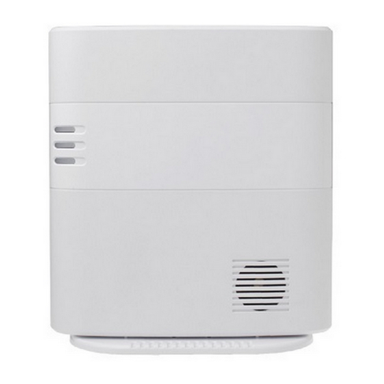
2. System Overview 2.1. Identifying the Parts Top View Back View ... - Page 7 Control Panel Definitions Button/LED/Component Behavior Function/Indication Red Help Button Pressed in idle/normal mode To summon emergency help Pressed once in learning To select Pendant #2 mode Pressed for 3 seconds in To delete a selected pendant learning mode Red Backlight Dimly lit Idle/normal mode Blinking...
- Page 8 Button/LED/Component Behavior Function/Indication Green Backlight Blinking (on MX-2 and MX-6 The Control Panel has a only) phone line fault. Yellow Button can Pressed once when serving To toggle on/off the inactivity serve as: as an inactivity, check-in/out timer Inactivity Button or away/home button Check-in/out Button Pressed once when serving...
- Page 9 Button/LED/Component Behavior Function/Indication 18 GPRS/GSM or 3G Fault Failed registration Indicator (orange) < > < > Registration will fail when an AC power failure occurs. Successful registration 19 GPRS/GSM or 3G Blinking When the GPRS/GSM or 3G Status Indicator (red) module operates normally 20 GPRS/GSM or 3G Reset Pressed for one second...
-
Page 10: Power Supply
2.2. Power Supply Plug the AC power adapter into the Control Panel’s DC jack and connect to the mains power. Make sure that you use an adapter with the appropriate AC voltage rating to prevent component damage. An AC-DC 12V/2A switching power adapter is generally used to power the standard version of the Control Panel. -
Page 11: Installing Mx
3. Installing MX Step 1. Choose a suitable location for the Control Panel. The Control Panel requires the mains power and PSTN (MX-2 and MX-6), GSM/3G (MX-3 and MX-8) and/or Ethernet (MX-6 and MX-8) connections and should be easily accessible. It should not be placed in a damp location such as a bathroom or close to a heat source like a microwave oven, which could reduce signal strength. -
Page 12: Programming Mx
4. Programming MX 4.1. PC Programming 4.1.1. Installing USB Driver Please first install the USB Driver provided in your CD-ROM on your PC. < < > > It is recommended that you use Windows XP or Windows 7 operating systems. Step 1. - Page 13 Step 3. Click on the “Device Manager” icon and find “MOBIL PERS BASE ISP” under “Other devices.” Click “Update Driver.” 10 ...
- Page 14 Step 4. When the Hardware Update Wizard window pops up, select “Install from a list or specific location (Advanced)” and click “Next.” 11 ...
- Page 15 Step 5. Search for the USB Driver folder. If you have copied and pasted the USB Driver folder to your desktop, tick “Include this location in this search” and click “Browse.” Step 6. Select the “USB Driver” and click “OK.” ...
- Page 16 Step 7. It takes a short while for your PC to install the USB Driver. If the Hardware Installation warning window pops up, please click “Continue Anyway.” 13 ...
- Page 17 Step 8. When the installation has been completed, click “Finish” on the Hardware Update Wizard window to close the wizard. 14 ...
- Page 18 Step 9. Please remember the COM port number of MX as shown in the “Device Manager” section. You will need the COM port number when doing PC programming. Now that the USB Driver has been successfully installed, you can proceed with PC programming of MX. ...
-
Page 19: Pc Programming Tool
4.1.2. PC Programming Tool You can easily configure the Control Panel via the PC Programming Tool provided in the CD-ROM. Step 1. Find and open the “PC Programming Tool” folder in the supplied CD-ROM. Click “MPTool_x.xx.exe” to execute the programming tool. ... - Page 20 Step 2. Select the following settings in the top section of the configuration screen and click “Open.” Port: Select the COM port generated for MX after installing the USB Driver (the USB port connected to MX). Baud rate: 115200 Data: 8 Parity: None Stop: 1 FlowCtrl: None...
- Page 21 Step 3. Enter SMS Keyword and Access Code and click “Read.” When a pop-up window shows “Read configuration success,” configuration page below will be opened and you can proceed with the programming of MX. SMS Keyword: PROG (default) Access Code: 1111 (default) ...
- Page 22 Step 4. SMS Program Click “SMS Program” to set a SMS Keyword (15 characters max.) and a PIN Code (4-8 digits) and click “Write.” Please note that the SMS Keyword is case-sensitive. < > < > The version of your MX model will be shown on the top of the screen. ...
- Page 23 Step 5. APN Click “APN” to set APN Name, APN User and APN Password and click “Write.” Access Point Name (APN): The name of an access point for GPRS. Please ask your SIM card service provider for your APN. Username: Offered by your SIM card service provider. Please ask your service provider for your GPRS username.
- Page 24 Step 6. Reporting Click “Report” to program destinations of reporting, event filters (Event), reporting formats (Type), follow-on options (Follow-on) and reporting sequence (Group 1~5) for alarm reporting and status reporting. Click “Write” after you have completed the settings. Destinations of reporting 1~8: Program destinations of reporting 1~8 in the No.
- Page 25 Group 1~Group 5: Groups 1~5 determine the sequence of reporting. The reporting sequence goes from Group 1 to Group 5. The procedure and details of programming are as follows: 1. Programming destinations of reporting: You can set 8 destinations of reporting.
- Page 26 process events according to the categories to which they belong. Please refer to “Appendix 7.1.9. Contact ID Event Codes” to check out the categories to which events are assigned. Events are divided into four categories: medical, emergency, status and burglary. If the option “all” is selected for a destination, all events will be reported to this destination.
- Page 27 Therefore, the system will skip the rest of the destinations in this group and go on reporting to the next group. For example, if destinations 2, 4 and 7 are assigned to Group 3 and the system has successfully reported to destination 2, the system will skip destinations 4 and 7 and go on reporting to Group 4.
- Page 28 Step 7. Non-Emergency Call Click “Non-Emergency Call” to program the non-emergency call number and click “Write.” When the Control Panel is in normal mode, you can make a non-emergency call by pressing the green reset button for 3 seconds or press the yellow button once (if the yellow button has been programmed as a non-emergency call button).
- Page 29 Click “Setting” to program “Guard Time Normal,” “Guard Time for Fall Sensor,” “Auto Check-In Interval,” “Auto Check-in Offset,” “Yellow Away/Home Button,” “Inactivity Timer,” “Inactivity Interval,” “Inactivity Warning Time,” “Callback Timer,” “Two-Way Timer,” “Supervision Timer Interval” and “Speaker Volume Two-Way,” “Speaker Volume Talk Only,” “Speaker Volume Other,” Sound Setting Guard Beep,”...
- Page 30 You can set a guard time period for Fall Sensor. A voice prompt announcing “a fall has been detected” will be played every 2-3 seconds during Fall Sensor’s guard time. If a false alarm is triggered by Fall Sensor, it can be canceled within the guard time period.
- Page 31 As an away/home button: The user can use the away/home button to toggle on/off the inactivity timer. When the user presses the away/home button to toggle off the inactivity timer before leaving home, the CID event code 666 with the prefix “1” will be reported to the CMS and two-way communication will be opened after the reporting.
- Page 32 enabled, the user can stop the inactivity timer when arming his house and restart the inactivity timer when disarming his house. < > < > Please set the inactivity timer as “off” if you program the yellow button as a non-emergency call button or a security button.
- Page 33 directly. DTMF commands switch communication methods. The Access Code must be entered within 15 seconds, otherwise the system will disconnect the call automatically. Press DTMF (9) or the reset button on the Control Panel to terminate the call. When callback time is up, the system will automatically exit the waiting mode and return to idle mode.
- Page 34 beeping sound during guard time. 16. Sound Setting Confirm Beep: Select “on” to enable confirmation beeps during reporting or “off” to disable confirmation beeps during reporting. 17. Answering Incoming [Calls]: When this function is set as “on,” the Control Panel rings for incoming calls.
- Page 35 Step 9. Click “Network” to configure networking settings. Select “Enable” or “Disable” for the DHCP setting: Enable: Select “Enable” if a DHCP server is present to enable settings to be automatically assigned from the server. If you select “Enable,” you can skip the “IP Address,”...
- Page 36 Step 10. Sensors 1. Viewing the data of sensors: When you have learned sensors into the Control Panel via the local learning method (see 5.1. Learning in Pendant #1, Pendant #2 and Other Devices), you can click “Sensors” and “Read” to view the zone numbers, types, battery status, tamper conditions, operating status and sound attributes of all of the sensors that have been learned in.
- Page 37 2. Adding sensors: In addition to the local learning method, you can also use the “Add Sensor” section on the “Sensors” page to learn sensors into the Control Panel. Enter the zone number (Zone 1~Zone 100) to which you wish to assign a sensor and the Sensor ID, which is the barcode on the back of the sensor, and click “Add Sensor.”...
- Page 38 3. Editing and removing sensors: Editing the sound attribute of a sensor: Click any box in the section of the sensor that you wish to configure. For example, if you wish to edit the sound attribute of the sensor in Zone 3, you can click any box in the Zone 3 section.
- Page 39 Step 11. System When you click “System” to enter the “System” screen, you can carry out the following operations: 1. Rebooting the Control Panel: You can click “Reboot Base” to reboot the Control Panel. The Control Panel will emit 2 beeps about 2 seconds after you click the “Reboot Base”...
- Page 40 2. Rebooting GSM: If this command is successful, the message “<OK> RSTG” will be shown at the bottom left-hand corner of the screen. 37 ...
- Page 41 3. Checking the condition of the Control Panel: You can click “Alive” to check if the Control Panel can respond to your commands properly. If the Control Panel responds properly, the message “<OK> ECHO” will be shown at the bottom left-hand corner of the screen. ...
- Page 42 4. Restoring the system to factory settings: You can click “Factory Reset” to restore the system to factory settings. The system will immediately restore all programmed parameters to factory settings and the Control Panel will emit 2 beeps after you click the “Factory Reset”...
- Page 43 5. Selecting an event code: You can select the event code to be sent to the CMS when the red button of the Control Panel is pressed. Choose your preferred event code in the box after “Help Event” and click “Write.” There are four options for the event code: 100: Medical 101: Emergency...
- Page 44 6. Jamming reports: You can select to enable or disable jamming reports. Select your setting in the box after “Jamming Report” and click “Write.” Jamming reports can only be sent in the CID format and not in the Scancom or Tunstall format. ...
- Page 45 7. AC power failure reports: You can disable AC power failure reports or set the interval between an AC power failure and the reporting of the power failure. Select your setting in the box after “AC Fail Report” and click “Write.” ...
- Page 46 8. The help arrival function: You can select to enable or disable the help/nurse arrival function. 43 ...
- Page 47 Step 12. Firmware Update You can update the firmware of MX by clicking on the “Firmware Update” and the “Open File” buttons. Select the provided firmware and a “Firmware Updating! Do not close program!” pop-up window will appear. Click “OK” on the pop-up window for the updating process to begin.
- Page 48 When the firmware update is complete, a pop-up window will show “Please wait for Panel restart.” Click “OK” on the pop-up window. The countdown to the restart of the Control Panel will appear in the white space at the bottom of the page. After the countdown, the Control Panel will restart and emit 2 beeps.
- Page 49 Step 13. RF Sniffer “RF Sniffer” is designed for the Control Panel to report to the monitoring center when it receives a signal from a RF device that it has not learned. If you select “Disable,” the Control Panel will not report to the monitoring center when receiving such a signal.
-
Page 50: Web Programming
4.2. Web Programming 4.2.1. Installing the Finder Software < > < > This installation is required only of the first-time user. Web programming is applicable to MX-6 and MX-8 only. Before you begin web programming, please make sure that you have plugged an IP cable into the Control Panel’s Ethernet port and connected the cable to an Ethernet network for MX to operate via Ethernet. - Page 51 Step 7. Click “Finder.exe” to start the installation. The following screen will be displayed: Step 8. Click on “Search” for the software to start searching for a recognized IP address within the local network service. Step 9. You will be able to see your MX’s IP address on the list. The pop-up window will display the product version and the MAC address of your MX.
- Page 52 < > < > If you need to enter your internet data manually, click on the “Configure Setting” button. Enter your internet data, the MX username (default: admin) and password (default: admin1234) and click on “OK” to confirm the settings. If the username and password are correct, a pop-up window will display “Status: Configure success!!”...
-
Page 53: Programming Mx
4.2.2. Programming MX Step 1. Getting Connected to the Welcome Page The welcome page to which your MX is connected will show the following information: Firmware revision: The firmware version of the Control Panel MAC address: The MAC address of your MX ... - Page 54 Step 2. Programming the Control Panel Click on “Panel” at the top of the page to enter the “Panel Setting” page and to configure the Control Panel’s settings. Click on “Submit Query” to save your settings or click on “Reset” to return to default settings. The details are as follows: 1.
- Page 55 At 20 and 10 seconds before the communication time expires, 1 beep will be emitted via the telephone handset to alert the user. When the communication time is up, the call will be automatically terminated. The communication time of non-emergency calls is conditioned by the two-way timer function.
- Page 56 check-in report once according to the setting of the offset period. Afterwards it will send reports according to the setting of auto check-in reports unless the Control Panel restarts or the offset period is reset. When the offset period is reset in programming mode, the system will recalculate the time for a check-in report.
- Page 57 security button. 14. Yellow Button: You can set the yellow button on the Control Panel as an inactivity button, check in/out button, away/home button, non-emergency call button or a security button. As an inactivity button: The user can use the inactivity button to toggle on/off the inactivity timer.
- Page 58 If the inactivity timer is set as “off,” it will remain disabled no matter whether the user arms or disarms his house. The orange backlight of the yellow button will be turned off. 15. Inactivity Timer: Inactivity Timer: If you set the inactivity timer as “On,” the orange backlight of the yellow button on the Control Panel will be steady on to indicate that the inactivity timer is on.
- Page 59 The Control Panel will play a voice prompt upon the expiry of the inactivity timer. Afterwards the voice prompt will be played every 5 minutes during the warning interval as a reminder to the user until the expiry of warning time. If the warning interval is disabled, an inactivity alarm report will be immediately sent to the CMS upon the expiry of the inactivity timer.
- Page 60 failure period. 19. Answering Incoming [Calls]: When this function is set as “On,” the Control Panel rings for incoming calls. You can answer an incoming call by pressing the red help button on the Control Panel. When this function is set as “Off,” the Control Panel remains silent during incoming calls.
- Page 61 defaults. < > < > After you click on “Submit Query” to save the settings, these words “Updated successfully” will be shown at the top the page to confirm that the Control Panel’s settings have been successfully updated. 58 ...
- Page 62 Step 3. APN Click on “Mobile” at the top of the page. Configure GPRS settings and click on “Submit Query” to save your settings. Click on “Reset” if you want to restore the settings to default values. The details are as follows: 1.
- Page 63 5. Reset GSM: If this command is successful, the words “Updated successfully” will be shown at the top of the page. Step 4. Network Settings Select “On” or “Off” for the DHCP setting. DHCP “On”: Select “On” if a DHCP server is present to enable settings to be automatically assigned from the server.
- Page 64 Step 5. User Code (Access Code) Program user code(s) on this page and click on “Submit Query” to save your setting(s). The default is 1111. 61 ...
- Page 65 Step 6. Report Settings Click “Report” to program destinations of reporting, event filters (Event), reporting formats (Type), follow-on options (Option) and reporting sequence (Group 1~5) for alarm reporting and status reporting. Click on “Submit Query” after you have completed the settings. Destinations of reporting 1~8: Program destinations of reporting 1~8 in the No.
- Page 66 The follow-on options include the following: No, 2-way voice communication, talk only, listen-in only and wait (for command). The follow-on options should be in conformity with the settings of their corresponding destinations of reporting. Group 1~Group 5: Groups 1~5 determine the sequence of reporting. The reporting sequence goes from Group 1 to Group 5.
- Page 67 events according to the categories to which they belong. Please refer to “Appendix 7.1.9. Contact ID Event Codes” to check out the categories to which events are assigned. Events are divided into four categories: medical, emergency, status and burglary. If the option “all” is selected for a destination, all events will be reported to this destination.
- Page 68 Therefore, the system will skip the rest of the destinations in this group and go on reporting to the next group. For example, if destinations 2, 4 and 7 are assigned to Group 3 and the system has successfully reported to destination 2, the system will skip destinations 4 and 7 and go on reporting to Group 4.
- Page 69 Step 7. Device List The page of device list is only for you to view device status. You can learn in or remove devices via local commands or use the PC Programming Tool to learn in, remove or edit devices. 66 ...
- Page 70 Step 8. RF Sniffer “RF Sniffer” is designed for the Control Panel to report to the monitoring center when it receives a signal from a RF device that it has not learned. If you select “Off,” the Control Panel will not report to the monitoring center when receiving such a signal.
- Page 71 Step 9. Firmware Update You can update the firmware of MX by clicking on “Firmware” and “Browse.” Select the provided firmware and click “Submit” for the updating process to begin. The firmware update will take a few minutes. When the updating process is finished, the upper left-hand corner of the page will show “OK, please wait for reboot and don’t power off the panel.”...
-
Page 72: Sms Programming
4.3. SMS Programming You can do SMS remote programming via a mobile phone or SMS iWizard. SMS Remote Programming via a Mobile Phone < > < > Please change the language setting of your mobile phone to English before you proceed with SMS remote programming. Step 1. - Page 73 Comma 1111 Access Code Comma Programmed parameter < > < > You can compose multiple commands in one SMS text message by using “;” to separate each command. SMS Remote Programming Commands Table Item Command Example & Usage Default GPRS APN, APN:PROG,1111,internet,, APN: Internet username &...
- Page 74 To set the Access Code (index number, code) 8 digits max. for the Access Code Guard time GUDT GUDT:PROG,1111,10,15 10, 15 settings To set the length of guard time periods (system: 0~180 seconds, fall sensor: 0~180 seconds) Auto check-in TESTC TESTC:PROG,1111,720,60 720, 60 reports...
- Page 75 RF jamming JAMRP JAMRP:PROG,1111,1 reports To enable/disable RF jamming reports 1 = enable 0 = disable AC power ACFRP ACFRP:PROG,1111,5 failure reports To disable AC power failure reports or to set the interval between an AC power failure and the reporting of the power failure 0 = disable 1-60 = 1~60 minutes...
- Page 76 SMS Remote Programming via SMS iWizard MX is compatible with Climax’s SMS iWizard, which is designed to facilitate SMS remote programming via a PC. This tool allows you to conveniently program MX from your PC without sending SMS text messages from a mobile phone.
-
Page 77: Device Management
5. Device Management You can use the local learning method to learn 100 devices into the Control Panel. Up to 4 DECT devices (DECT devices include WTRVS, CP-23 and CTC-808RV) can be learned into the Control Panel. Devices that can be learned into the Control Panel include the following: Door Contact: DC Remote Control: RC... -
Page 78: Learning In Pendant #1, Pendant #2 And Other Devices
The device attribute of KP is set as “personal attack” when the dual-key function “1” + “3” is enabled. When the keys “1” and “3” are pressed on KP at the same time, the Control Panel will report CID code 120 to the CMS. The device attribute of KP is set as “fire”... - Page 79 For Talking Pendant (WTRVS) or Call Point (CP-23) Step 1. When the Control Panel is in idle mode, press and hold the yellow button for 3 seconds to enter learning mode. Step 2. The Control Panel will emit 1 beep once the yellow button is pressed. Release the yellow button when you hear 2 beeps, which indicate the Control Panel is now in learning mode.
-
Page 80: Learning In Pendant #2
Step 4. Press and hold CTC-808RV’s learning button for 5 seconds until you hear 2 beeps. Release the button and CTC-808RV will emit one short beep to indicate it is now in learning mode. The green LED of CTC-808RV is turned on. Step 5. - Page 81 If the Control Panel emits 3 beeps, that means a sensor has been previously assigned to Zone 2. For Talking Pendant (WTRVS) or Call Point (CP-23) Step 1. When the Control Panel is in idle mode, press and hold the yellow button for 3 seconds to enter learning mode.
-
Page 82: Learning In Other Devices
to blink. Step 3. Press the red help button once. The Control Panel will emit 1 beep. Step 4. Press and hold CTC-808RV’s learning button for 5 seconds until you hear 2 beeps. Release the button and CTC-808RV will emit one short beep to indicate it is now in learning mode. -
Page 83: Removing Pendant #1, Pendant #2 And Other Devices
The green reset button on the Control Panel assigns a pendant to Zone 1 and the red help button a pendant to Zone 2. If the green reset button or the red help button is not pressed, devices will be automatically assigned to Zone 3~Zone 100 by sequence. -
Page 84: Operation
6. Operation 6.1. Control Panel 6.1.1. Idle Mode When the Control Panel is in idle mode, it is ready to execute the following functions. 6.1.1.1. Answering Incoming Calls The Control Panel emits cycles of 2 quick beeps for an incoming call. The user can answer the call by pressing the red help button on the Control Panel. -
Page 85: Non-Emergency Calls
another preset communication period. Communication periods are conditioned by the two-way timer function. When a DTMF key is pressed, its designed shortcut function will be executed and the communication time extended simultaneously. If the speaker volume level is adjusted in two-way communication mode, the adjusted value will be kept for the next usage. -
Page 86: Ac Power Checkup
be emitted via the telephone handset to alert the user. Step 3. Press DTMF (9) or the non-emergency call button to terminate the call. The green backlight dims and the Control Panel returns to idle mode. Making a non-emergency call from CTC-808RV Step 1. -
Page 87: Control Panel Low On Battery
an AC failure report to the CMS. < > < > The interval between an AC power failure and the Control Panel’s sending the AC failure report (factory default is 5 minutes) is programmed as explained in Step 10. System of 4.2. PC Programming Tool. After AC power has been restored for more than 5 minutes, the Control Panel will send an AC power restored report to the CMS. -
Page 88: Automatic Check-In Reports
6.1.1.7. Automatic Check-In Reports When the Control Panel is programmed to send auto check-in reports, it will dispatch the reports to the CMS accordingly. After the Control Panel is powered on, the first auto check-in report it sends will be conditioned by the setting of the offset timer. Afterwards auto check-in reports will be sent according to the setting of the auto check-in timer. - Page 89 and the inactivity timer will automatically restart. < > < > If the inactivity timer is set as “on,” the timer will stop counting when the user arms his house and goes out. The timer will start counting all over again when the user returns home and disarms the house.
- Page 90 The user can turn on/off the inactivity timer when the yellow button is programmed as an inactivity button, a check-in/out button or an away/home button. If the inactivity timer is set as “on” and the yellow button is programmed as a security button, the user can stop the inactivity timer when arming his house and restart the inactivity timer when disarming his house.
-
Page 91: Alarm Activation
Home: On Control Panel (Inactivity timer is reporting. The red backlight goes off when the reporting ends. Security button None On: Inactivity Please refer to None timer on section 6.2.3. Off: Inactivity timer off 6.1.2. Alarm Activation Alarm triggered by the Control Panel, WTRVS/CP-23 or CTC-808RV Alarm triggered by the Control Panel When an alarm is triggered, the Control Panel will enter guard time. - Page 92 conducted via PSTN. Alarm triggered by Talking Pendant (WTRVS) or Call Point (CP-23) Press the button on WTRVS/CP-23 to trigger an alarm. WTRVS/CP-23 will emit confirmation beeps until it receives a DTMF command. The reception of a DTMF command indicates that the connection has been set up successfully.
- Page 93 Access Point Name (APN): The name of an access point for GPRS. Please ask your SIM card service provider for your APN. Username: Offered by your SIM card service provider. Please ask your service provider for your GPRS username. If no username is required, you may skip this step.
- Page 94 its designed shortcut function will be executed and the communication time extended simultaneously. < > < > If you wish to enable a designed shortcut function, please press the DTMF key for over 1 second to enable the function. When your programmed choice is follow-on or follow-on & callback, what follows will be two-way voice communication, listen-in, or waiting for commands depending on your setting.
- Page 95 to end the call. Enter ( * ) to toggle. Press (6) or (4) to increase or decrease the speaker volume level in two-way communication mode. You can also press the volume switches on the Control Panel to adjust the speaker volume level. Press any DTMF key except for the designed hang-up key (5) to add another preset communication period.
- Page 96 Enter (3) to listen in only. Enter (9) to hang up. You can also put the handset back to the base cradle to end the call. Press (6) or (4) to increase or decrease the speaker volume level in two-way communication mode. You can also press the volume switches on the Control Panel to adjust the speaker volume level.
- Page 97 CID code 1-661 to the CMS. Step 3. After the nurse has helped the user and completed his/her job, he/she presses the green reset button on the Control Panel again to signal that his/her job has been completed. The Control Panel sends CID code 3-661 to the CMS.
- Page 98 < > < > Pressing the green reset button on the Control Panel anytime during nurse arrival mode will terminate nurse arrival mode. The Control Panel will send CID code 1-663 to the CMS. Scenario 5: Step 1. The user presses the red help button on the Control Panel or a device to summon help.
- Page 99 Press the WTRVS/CP-23 button for 8 seconds. Press the cancel button on CTC-808RV for 8 seconds. If no DTMF command is pressed during the speech period, the call will automatically hang up and be recorded as an unsuccessful one. Each phone number will be retried up to a maximum of 3 times accordingly.
-
Page 100: Arming/Disarming The System
successfully received after the system has gone through the second round, the system will again take a 5-minute break before starting the third round of reporting. The system will never stop the reporting cycles unless one reporting has been received successfully. Retry Method Retry cycle: Each phone number can be retried up to 3 times in one round. - Page 101 button within 3 seconds after the yellow button is pressed. The Control Panel will emit two beeps to signal that it has entered disarmed mode. < > < > Remote Control (RC), Keypad (KP) or Tag Reader (TG-7) is required to disarm the system.
-
Page 102: Voice Prompts
6.1.4. Voice Prompts The Control Panel plays voice prompts on important occasions to report its condition or remind you to take a specific action. Information on voice prompts is provided in the chart below. The Control Panel’s Voice Prompts Voice Prompt Condition Emergency call was pressed. -
Page 103: Walk Test (Range Test)
restored Inactivity timer expiring. Please reset. Played upon the expiry of the inactivity timer once every 5 minutes afterwards for 6 times (over a 30-minute period). After the 30 minutes, the Control Panel will start reporting (this warning period is conditioned by the inactivity warning timer and its default is 30 minutes). -
Page 104: Appendix
Step 3. Plug the power cord into the DC jack while pressing both the help and the reset buttons until one long beep is emitted to indicate the factory reset has been successfully executed. Step 4. Release both buttons. Step 5. Slide the battery switch back to the on position. <... -
Page 105: Message Blocks
7.1.4. Message Blocks A message block is sent by MX. Each message block contains sufficient information to report an event in the system. 7.1.5. Placement The first message block is sent beginning 250 msec. (250 min., 300 max.) after the end of either the handshake tone sequence or after a kiss off (acknowledgement) tone. -
Page 106: Kiss Off (Acknowledgement) Tones
Burst OFF time – 50 msec. (50 min., 60 max.) 7.1.8. Kiss off (Acknowledgement) Tones The kiss off tone from the receiver is used to tell MX that the message has been received successfully. The frequency of the tone is 1400 Hz. ± 3%. MX detects a minimum of 400 msec. - Page 107 When the Control Panel is unable to receive a signal transmitted from a sensor for a period preset by the supervision timer. 151 – Gas Emergency (emergency) When Gas Detector is triggered. 154 - Water Emergency (emergency) When Water Sensor (WS) is triggered. 158 –...
-
Page 108: Sia Digital Communication Standard
When the Control Panel makes an inactivity timer expired report. < > < > This event code will be sent with fixed zone number 072. 661 – Nurse or Help Has Arrived/Nurse’s Job Completed (medical) When the green reset button on the Control Panel is pressed to signal that a nurse or help has arrived (1-661). -
Page 109: Scancom Event Codes
1100 00 000 = CID data (QXYZGGCCCC) [X...] and [Y...] are location data. [P...] stands for the margin of error of cell location. 7.3. Scancom Event Codes 515555517 - Control Panel Emergency/Pendant #1 Emergency/Fall Emergency/WTR Emergency/PB Emergency (when two-way mode is set for follow-on operation) When the red help button on the Control Panel is pressed. -
Page 110: Tunstall Ttnew Event Codes
When the Control Panel’s AC power fails for more than 10 seconds, the green LED blinks every second. 555553557 - AC Power Restored/Control Panel’s Low Battery Status Cleared/Control Panel’s Battery Disconnected Status Cleared When AC power is restored to the Control Panel. When the Control Panel’s low battery status is cleared. -
Page 111: Climax Cpc Dialect Event Codes
seconds. D#1015 – Inactivity When the Control Panel makes an inactivity timer expired report. An inactivity code will be sent to the CMS if there is no movement during guard time after fall detection. D#1016 - Personal Emergency or Fall Emergency When Wrist Transmitter/Emergency Pendant (WTR) or Fall Sensor is pressed. - Page 112 When Fall Sensor is triggered. 14 - Inactivity An inactivity code will be sent to the CMS if there is no movement during guard time after fall detection. 21 - WTR Supervision Failure When the Control Panel is unable to receive a signal transmitted from a sensor for a period preset by the supervision timer.
-
Page 113: Franklin Event Codes
32 - RF Jam Detection When the Control Panel’s RF signal is interfered. 7.6. Franklin Event Codes < > < > The Franklin reporting format is “4 + 2,” 4 standing for “account number” and 2 for “trigger code (1 digit) + zone number (1 digit).” The showing of the zone number adopts the hexadecimal notational system. - Page 114 2X - Help Needed Due to Detected Fire, Smoke, Gas, Carbon Monoxide or Water Leakage When fire, smoke, gas, carbon monoxide or water leakage is detected, SD, CO and WS will be triggered. 4X - Crisis of Fire, Smoke, Gas, Carbon Monoxide or Water Leakage is relieved.
- Page 115 When the Control Panel is unable to receive a signal transmitted from a sensor for a period preset by the supervision timer. FX – Sensor’s Supervision Failure Status Cleared When a sensor’s supervision failure status is cleared. 112 ...
- Page 116 Federal Communication Commission Interference Statement This equipment has been tested and found to comply with the limits for a Class B digital device, pursuant to Part 15, 22 & 24 of the FCC Rules. These limits are designed to provide reasonable protection against harmful interference in a residential installation.
Need help?
Do you have a question about the Vesta Series and is the answer not in the manual?
Questions and answers
The unit is ticking and the battery is new but the app says low battery- how can we fix this problem?
If the Climax Technology Series unit is ticking despite having a new battery, the issue may be due to:
1. The battery switch not being in the ON position.
2. The backup battery being dead, missing, or dysfunctional.
3. The panel not detecting the battery.
To resolve the issue:
- Ensure the battery switch is slid to the ON position.
- Confirm the battery is properly connected and functional.
- Check if the panel detects the battery after installation.
If the issue persists, the panel may still not detect the battery due to a fault.
This answer is automatically generated