Advertisement
Available languages
Available languages
WARNING
FIRE OR EXPLOSION HAZARD
If the information in these instructions is
not followed exactly, a fire or explosion
may result causing property damage,
personal injury or loss of life.
— Do not store or use gasoline or other
flammable vapors and liquids in the
vicinity of this or any other appliance.
— WHAT TO DO IF YOU SMELL GAS
•
Do not try to light any appliance.
•
Do not touch any electrical switch; do
not use any phone in your building.
•
Leave the building immediately.
•
Immediately call your gas supplier
from a neighbor's phone. Follow the
gas supplier's instructions.
•
If you cannot reach your gas supplier,
call the fire department.
— Installation and service must be
performed by a qualified installer,
service agency or the gas supplier.
INSTALLATION INSTRUCTIONS
AND OWNER'S MANUAL
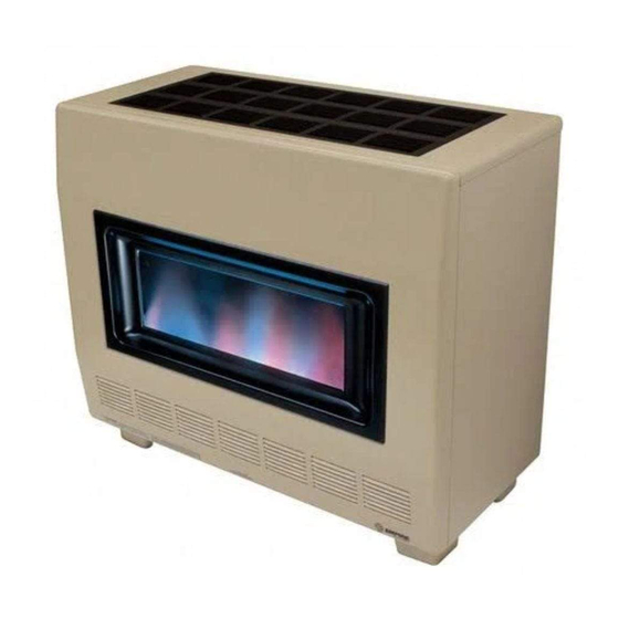
RH-50-7 Shown
VENTED
ROOM HEATER
MODELS
RH-50-7
RH-50C-2
INSTALLER:
Leave this manual with the appliance.
CONSUMER:
Retain this manual for future reference.
WARNING
If not installed, operated and maintained
in accordance with the manufacturer's in-
structions, this product could expose you to
substances in fuel or from fuel combustion
which can cause death or serious illness.
RH-65-7
RH-65C-2
Page 1
Advertisement
Chapters

Related Manuals for Empire RH-50-7


Summary of Contents for Empire RH-50-7
- Page 1 AND OWNER'S MANUAL VENTED ROOM HEATER MODELS RH-50-7 RH-65-7 RH-50C-2 RH-65C-2 RH-50-7 Shown INSTALLER: WARNING Leave this manual with the appliance. FIRE OR EXPLOSION HAZARD CONSUMER: If the information in these instructions is not followed exactly, a fire or explosion Retain this manual for future reference.
-
Page 2: Table Of Contents
TABLE OF CONTENTS SECTION PAGE IMPORTANT SAFETY INFORMATION ........................3 SAFETY INFORMATION FOR USERS OF PROPANE gAS..................4 INTRODUCTION ..............................5 - 6 SPECIFICATIONS ................................ 6 gAS SUPPLY ................................7 CLEARANCES ................................8 VENTINg ..................................8 VENTINg gUIDELINES .............................. 9 VENT SAFETY SHUTOFF SYSTEM ......................... -
Page 3: Important Safety Information
IMPORTANT SAFETY INFORMATION THIS IS A HEATING APPLIANCE DO NOT OPERATE THIS APPLIANCE WITHOUT FRONT PANEL INSTALLED. • Due to high temperatures, the room heater should • DO NOT put anything around the heater that will be located out of traffic and away from furniture and obstruct the flow of combustion and ventilation air. -
Page 4: Safety Information For Users Of Propane Gas
SAFETY INFORMATION FOR USERS OF PROPANE GAS Propane is a flammable gas which can cause fires and ex- point with the members of your household. Someday, when plosions. In its natural state, propane is odorless and color- there may not be a minute to lose, everyone’s safety will de- less. -
Page 5: Introduction
INTRODUCTION Introduction The base referred to above does not mean the fire-proof base as Always consult your local Building Department regarding regula- used on wood stoves. The protection is primarily for rugs that may tions, codes or ordinances which apply to the installation of a be extremely thick and light-color tile that can discolor. vented room heater. Floor pad is available from Empire Comfort Systems, Inc., Part Number RH-425. Instructions to Installer 1. Installer must leave instruction manual with owner after instal- Qualified Installing Agency lation. Installation and replacement of gas piping, gas utilization equipment 2. Installer must have owner fill out and mail warranty card sup- or accessories and repair and servicing of equipment shall be per- plied with heater. formed only by a qualified agency. The term “qualified agency” means 3. Installer should show owner how to start and operate heater any individual, firm, corporation, or company which whether in person and thermostat. or through a representative is engaged in and is responsible for (1) the installation or replacement of gas piping or (b) the connection,... -
Page 6: Specifications
INTRODUCTION (CONT'D) When an existing Category 1 heater is removed or replaced, the improperly sized venting system (formation of condensate, leakage, original venting system may no longer be sized to properly vent the spillage, etc.) and shall specify the following test procedure: attached appliances. Instructions shall also indicate effects of an WARNING Turn on clothes dryers and any appliance not connected CARBON MONOXIDE POISONING HAZARD to the venting system. Turn on any exhaust fans, such Failure to follow the steps outlined below for each as range hoods and bathroom exhausts, so they are appliance connected to the venting system being placed operating at maximum speed. -
Page 7: Gas Supply
GAS SUPPLY Compounds used on threaded joints of gas piping shall be resistant RECOMMENDED GAS PIPE DIAMETER to the action of liquefied petroleum gases. The gas lines must be Schedule 40 Pipe Tubing, Type L checked for leaks by the installer. This should be done with a soap Pipe Inside Diameter Outside Diameter solution watching for bubbles on all exposed connections, and if Length unexposed, a pressure test should be made. Natural Propane Natural Propane Never use an exposed flame to check for leaks. Appliance must 0-10 feet 1/2” 3/8”... -
Page 8: Clearances
CLEARANCES Clearances: When facing the front of the room heater the Do not install in alcove or closet. minimum clearances to combustible construction (material) No horizontal projection above heater permitted within 55 are the following: inches (140 cm). Ceiling 55 inches (140cm) Left side - 6 inches (152mm) Draft hood to rear wall 2 inches (51 mm) Right side - 6 inches (152mm) Open in front to provide service, access, and clearance to Recommend 18 inches (457mm) on left side for servicing construction. VENTING 1. Flue pipe must be as large as the flue collar on the draft diverter. 1. The chimney must be lined and sized properly. Most masonry 2. Maintain an upward slope of at least 1/4 inch (6mm) per foot chimneys are over sized and absorb too much heat to be con- of horizontal run. sidered a proper vent. If you have any doubts line the chimney 3. Run flue pipe as directly as possible with a minimum of elbows. with the right size liner. If it’s unlined you must line it. 2. Use an insulated liner when the chimney is on the outside, 4. Flue pipe should extend through the wall of a chimney to be three sides exposed to the weather, and there is no clay liner flush with inner wall. 5. Flue pipe must be adequately supported by metal strips. in the chimney. The insulation will help keep the flue gases 6. Single wall vent pipe may be attached directly to the draft hood warmer. of the room heater when clearance of 2 1/2 inches (64mm) is Insulated Vent Enclosure maintained between the single wall vent pipe and the combustible Vented room heaters installed with the vent going directly to the... -
Page 9: Venting Guidelines
VENTING GUIDELINES The installer must consider all of the following venting rules. • Flue pipe MUST always have an upward slope (1/4 inch per foot minimum). • Flue pipe MUST run as directly as possible and have as few elbows as possible. • Flue pipe MUST be as large as the flue collar on the draft diverter. • The flue pipe MUST be on the outside of the draft diverter collar. • The flue pipe MUST be sealed. No open “Tees.” • The flue pipe’s vertical rise MUST always be at least twice the length of the horizontal run. • Each new piece of flue pipe that is connected when getting farther away from the furnace MUST connect on the outside of the previous one. Remember, the exhaust must flow “into” the next pipe. • For flue pipe running through walls, roof and within one inch of combustible construction, use B-1 (one inch clearance to combustibles) vent pipe. Any combustible material that is within 2 inches of the vent connection or the draft diverter must be shielded with a non-combustible material. • When connecting the flue pipe to the chimney, the pipe MUST go fully in and be cemented. The flue pipe MUST NOT go too far into the chimney. It should be cut off as it will interfere with normal venting. -
Page 10: Vent Safety Shutoff System
VENT SAFETY SHUTOFF SYSTEM This heater must be properly connected to a venting system. This This room heater is equipped with a vent safety switch. The vent heater is equipped with a vent safety shutoff system. safety switch will cause gas flow to the pilot to “shut off” due to improper venting or a blocked flue. Warning: If the vent safety switch continues to “shut off” the gas flow to the Operation of this heater, when not connected to a pilot, a qualified service person must be contacted to inspect for properly installed and maintained venting system or improper venting, blockage in the vent pipe or the vent safety tampering with the vent safety shutoff system, can result in switch for being defective. -
Page 11: Lighting Instructions
LIGHTING INSTRUCTIONS FOR YOUR SAFETY READ BEFORE LIGHTING WARNING If you do not follow these instructions exactly, a fire or explosion may result causing property damage, personal injury or loss of life. A. This appliance has a pilot which must be lighted by hand. C. -
Page 12: Pilot Flame Characteristics
PILOT FLAME CHARACTERISTICS The correct flame will be almost horizontal, blue and will extend past the thermocouple 1/4” (6mm). The flame will surround the thermocouple just below the tip. On Propane Gas slight yellow might occur where the pilot flame and the burner flame meet. Natural Gas pilots require adjusting when the inlet pres- sure is above 5” w.c. (1.25kPa). Remove pilot adjustment cover. Turn adjustment screw clockwise to reduce flame. Propane Gas will not require adjusting. Figure 5 MAIN BURNER FLAME CHARACTERISTICS There will be a short blue inner flame with a larger, lighter On Propane gas, if a whistling noise (resonation) oc- blue secondary flame. The burner flame may have yel- curs low tips when hot. Dust in the combustion air will produce a. Screw the air adjustment bolt into the burner throat to and orange or red flame. Do not mistake the orange or eliminate the whistling noise (resonation). red flame for an improper yellow flame. The flame will be b. Size main burner orifice with a drill bit. For RH-50(C) proper if the factory-set pressure and orifice are used. After use #47 drill bit. For RH-65(C) use 2.3mm drill bit. use, cleaning may be required for the proper flame. -
Page 13: Maintenance
MAINTENANCE Cleaning Pilot Burner Cleaning Combustion Chamber After use, cleaning of the pilot burner may be required for A qualified serviceman should remove the chamber and apply the proper flame. The pilot orifice can be cleaned with high air pressure to the inside in order to clear all passageways. pressure air or by placing under running water. Pilot orifice Primary Air Adjustment must be dry before replacement. Use a pipe cleaner to 1. A primary air adjustment bolt is located on left, front clean inside the pilot after the pilot orifice has been re- of burner throat. The bolt can be screwed into burner moved. throat to REDUCE primary air or unscrewed from burner Removing Pilot Orifice throat to INCREASE primary air. To reduce yellow flame 1. Disconnect the pilot supply line at the pilot burner on main burner, unscrew bolt from burner throat. Also,... -
Page 14: Parts List Rh-50 & Rh-65
PARTS LIST RH-50 & RH-65 PLEASE NOTE: When ordering parts, it is very important that part number and description of part coincide. Index Part Index Part Description Description 11723 Diverter Assembly Main Burner Orifice (RH-65-7 P86370 Natural) Down Draft Shield (RH-50-7 Natural RH802 & Propane-RH-65-7 Natural) Main Burner Orifice (RH-50-7 P8631 Natural) RH851 Down Draft Shield (RH-65-7 Propane) Main Burner Orifice (RH-65-7 11724 Draft Diverter Plate P86230 Propane) 11719 Casing Top (RH-50-7) Main Burner Orifice (RH-50-7 P8647 11720 Casing Top (RH-65-7) Propane) Louver (RH-50-7, 3 required) (RH-... -
Page 15: Parts View Rh-50 & Rh-65
PARTS VIEW RH-50 & RH-65 31910-8-0319 Page 15... -
Page 16: Parts List Rh-50C & Rh-65C
PARTS LIST RH-50C & RH-65C PLEASE NOTE: When ordering parts, it is very important that part number and description of part coincide. Index Part Index Part Description Description 11723 Diverter Assembly P206 Manifold Assembly (RH-50C) RH802 Down Draft Shield (RH-50C-2 P207 Manifold Assembly (RH-65C-2) RH851 Down Draft Shield (RH-65C-2 P86370 Main Burner Orifice (RH-65C-2 Natural) 11724 Draft Diverter Plate P8631 Main Burner Orifice (RH-50C-2 Natural) 11719 Casing Top (RH-50C-2) P86230 Main Burner Orifice (RH-65C-2 Propane) 11720 Casing Top RH-65C-2) P8647 Main Burner Orifice (RH-50C-2 Propane) Louver (RH-50C-2, 3 Required) RH856 Valve Bracket 11707 (RH-65C-2, 4 Required) -
Page 17: Parts View Rh-50C & Rh-65C
PARTS VIEW RH-50C & RH-65C 31910-8-0319 Page 17... -
Page 18: Optional Blower Installation Instructions
OPTIONAL BLOWER INSTALLATION INSTRUCTIONS FRB-3 FOR VENTED ROOM HEATERS MODELS RH-50-(1, 2, 3, 4, 5, 6, 7) RH-50C-(1, 2) RH-65-(1, 2, 3, 4, 5, 6, 7) RH-65C-(1, 2) Figure 7 Figure 8 Installing Optional Blower 1. Remove rear shield (2 screws) and bottom reflector (4 screws). See Figure 7. 2. Align blower cushion with bottom assembly air discharge opening. Foil face side of blower cushion should be placed upward. - Page 19 Attention: Wiring harness on blower is factory assembled and Wiring installed. If wiring harness becomes disassembled, use the fol- The appliance, when installed, must be electrically grounded in lowing steps to reassemble the wiring harness. accordance with local codes or, in the absence of local codes, with 1. Attach (1) pin terminal from black (hot) wire, smooth insulation the National Electrical Code, ANSI/NFPA 70 or Canadian Electrical on cord set to (1) socket terminal on fan control assembly. Code, CSA C22.1, if an external electrical source is utilized. This 2. Attach (1) pin terminal from black (neutral) wire, ribbed insula- appliance is equipped with a three-prong [grounding] plug for tion on cord set to (1) socket terminal from white (neutral) wire your protection against shock hazard and should be plugged directly into a properly grounded three-prong receptacle.
-
Page 20: Appliance Service History
APPLIANCE SERVICE HISTORY Date Dealer Name Service Technician Name Service Performed/Notes Page 20 31910-8-0319... - Page 21 APPLIANCE SERVICE HISTORY Date Dealer Name Service Technician Name Service Performed/Notes 31910-8-0319 Page 21...
-
Page 22: Master Parts Distributor List
MASTER PARTS DISTRIBUTOR LIST To Order Parts Under Warranty, please contact your local Empire dealer. See the dealer locator at www.empirecomfort. com. To provide warranty service, your dealer will need your name and address, purchase date and serial number, and the nature of the problem with the unit. To Order Parts After the Warranty Period, please contact your dealer or one of the Master Parts Distributors listed below. This list changes from time to time. For the current list, please click on the Master Parts button at www.empirecomfort.com. Please note: Master Parts Distributors are independent businesses that stock the most commonly ordered Original Equipment repair parts for Heaters, Grills, and Fireplaces manufactured by Empire Comfort Systems Inc. Dey Distributing F. W. Webb Company 1401 Willow Lake Boulevard 200 Locust Street Vadnais Heights, MN 55101 Hartford, CT 06114 Phone: 651-490-9191 Phone: 860-722-2433 Toll Free: 800-397-1339 Toll Free: 800-243-9360 Website: www.deydistributing.com... -
Page 23: Warranty
WARRANTY Empire Comfort Systems Inc. warranties this space heating product to be free from defects at the time of purchase and for the periods specified below. Space heating products must be installed by a qualified technician and must be maintained and operated safely, in accordance with the instructions in the owner’s manual. This warranty applies to the original purchaser only and is not transferable. All warranty repairs must be accomplished by a qualified gas appliance technician. Limited ten-Year Parts Warranty – combustion chamber Empire promises to the owner that if the combustion chamber (see parts list) fails because of defective workmanship or material with ten years from the date of purchase, Empire will repair or replace at Empire’s option. Limited one-Year Parts Warranty – Remote controls, thermostats, Accessories, and Parts Should any remote control, thermostat, accessory, or other part fail because of defective workmanship within one year from the date of purchase, Empire will repair or replace at Empire’s option. Duties of the owner The appliance must be installed by a qualified installer and operated in accordance with the instructions furnished with the `appliance. A bill of sale, cancelled check, or payment record should be kept to verify purchase date and establish warranty period. Ready access to the appliance for service. What is Not covered Damages that might result from the use, misuse, or improper installation of this appliance. - Page 24 Empire Comfort Systems Inc. Belleville, IL If you have a general question about our products, please e-mail us at info@empirecomfort.com. If you have a service or repair question, please contact your dealer. www.empirecomfort.com Page 24 31910-8-0319...
- Page 25 INSTRUCTIONS POUR L’INSTALLATION ET MANUEL DU PROPRIéTAIRE RADIATEUR INDIVIDUEL MODèLES RH-50-7 RH-65-7 RH-50C-2 RH-65C-2 RH-50-7 Représenté INSTALLATEUR : AVERTISSEMENT Laisser ce guide avec l’appareil. RISQUE D’INCENDIE OU D’EXPLOSION CONSOMMATEUR : Si les informations contenues dans ces instructions ne sont pas suivies à la lettre, Garder ce guide pour référence ultérieure.
- Page 26 TABLE DES MATIèRES SECTION PAGE INFORMATION IMPORTANTE DE SÉCURITÉ ......................3 INFORMATION DE SÉCURITÉ POUR LES UTILISATEURS DE PROPANE ............. 4 INTRODUCTION ..............................5 - 6 SPECIFICATIONS ................................ 6 ALIMENTATION EN gAZ ............................. 7 ESPACES LIBRES ............................... 8 ÉVACUATION ................................8 LE SYSTèME DE FERMETURE DE SûRETE DE L’éVENT ..................
-
Page 27: Information Importante De Sécurité
INFORMATION IMPORTANTE DE SéCURITé CECI EST UN APPAREIL DE CHAUFFAGE NE PAS FAIRE FONCTIONNER CET APPAREIL SANS QUE LA PAROI EXTéRIEURE SOIT INSTALLéE. • A cause des hautes températures, cet appareil doit être • NE rien mettre autour du radiateur qui pourrait obstruer le débit de combustion et la ventilation d’air. Voir les situé dans un endroit non achalandé et loin des meubles espaces libres. et des rideaux. • Les enfants et les adultes doivent être avisés des dan- • Les matériaux combustibles, la gazoline ou les vapeurs gers des parois très chaudes et doivent rester loin pour... -
Page 28: Information De Sécurité Pour Les Utilisateurs De Propane
INFORMATION DE SéCURITé POUR LES UTILISATEURS DE PROPANE Le propane est un gaz inflammable qui peut causer des feux et les membres de votre famille. Un jour, lorsqu’il n’y aura pas des explosions. Dans son état naturel, le propane est inodore et une minute à perdre, la sécurité de chacun dépendra de votre sans couleur. Peut-être que vous ne connaissez pas toutes les savoir-faire. Si après avoir lu les informations suivantes, vous précautions décrites ci-dessous? Elles peuvent vous protéger pensez avoir besoin de plus amples informations, s’il vous plaît ainsi que votre famille contre un accident. Lisez-les attentive- contactez votre fournisseur de gaz. -
Page 29: Introduction
épais et les tuiles de Instructions Pour l’Installateur couleur qui pourraient se décolorer. 1. Après l’installation, l’installateur doit laisser le manuel Une plateforme pour radiateur est disponible chez Empire Comfort d’instructions au propriétaire. Systems, Inc., Pièce numéro RH-425. 2. L’installateur doit demander au propriétaire de compléter et Agence D’installation Qualifiée poster la carte de guarantie de l’unité de chauffage. L’installation et le remplacement des tuyaux à gaz, des équipements 3. L’installateur doit expliquer au propriétaire la mise en marche... -
Page 30: Specifications
INTRODUCTION (suite) Lorsqu’un radiateur de catégorie 1 existant est retiré ou remplacé, le également indiquer les effets d’un système de ventilation de taille ina- système de ventilation d’origine peut ne plus être dimensionné pour déquate (formation de condensat, fuite, déversement, etc.) et doivent ventiler correctement les appareils raccordés. Les instructions doivent spécifier la procédure d’essai suivante: AVERTISSEMENT dé au système de ventilation. Allumez les ventilateurs DANGER D’EMPOISONNEMENT AU MONOXYDE DE CARBONE d’extraction, tels que les hottes de cuisine et les échappe- Le fait de ne pas suivre les étapes décrites ci-dessous pour ments de la salle de bain, afin qu’ils fonctionnent à... -
Page 31: Alimentation En Gaz
ALIMENTATION EN GAZ Ne jamais employer une flamme pour vérifier les fuites. Lors d’un Le Diamètre recommandé de tuyau de gaz test de pression, le tuyau d’arrivée de la valve de commande doit Le plan 40 tuyau Les tuyaux, Taper L être débranché de l’appareil et bouché. Ne jamais faire un test de Longuer de diameter d’intérieur Hor du Diamétre pression lorsque l’appareil est branché; la valve de commande tuyau Naturel Propane Naturel Propane peut être endommagée! -
Page 32: Espaces Libres
ESPACES LIBRES Espaces libres: Lorsque vous êtes devant le radiateur individuel, Ne pas installer dans une niche ou un placard. Aucune saillie les espaces libres minimum aux matériaux combustibles sont les horizontale est permise 55” (1.4m) au-dessus du radiateur. suivants: Plafond 55” (1.4m). Côté droit 6” (15.2cm) Côté gauche 6” (15.2cm) Coupe-tirage au mur arrière 2” (5cm). Pour l’entretien, nous recommendons 18” (45.6cm) pour le côté Ouvert à l’avant pour permettre l’accès, l’entretien et l’espace libre gauche. aux combustibles. éVACUATION évacuation zone de pression atmosphérique que l’entrée d’air de combustion 1. Le tuyau d’échappement doit être aussi large que le collet du de l’appareil. tuyau sur le coupe-tirage. Revêtement Intérieur et Revêtement Intérieur Isolant 2. Maintenir une pente ascendante sur la ligne horizontale d’au Lorsque vous installez un radiateur individuel à air pulsé dans moins 1/4” (6mm) pour chaque 12” (30.5cm). -
Page 33: Le Système De Fermeture De Sûrete De L'évent
LE SYSTèME DE FERMETURE DE SûRETE DE L’éVENT Cet appareil a besoin d’air frais pour un fonctionnement sécuritaire Cet appareil doit être branché correctement à un système et doit être installé de façon à ce qu’il y est un approvisionnement d’évacuation. Cet appareil est muni d’un système de fermeture satisfaisant pour une combustion et une ventilation d’air adéquate. de sûreté de l’évent. Ce radiateur individuel est muni d’un interrupteur de sûreté de AVERTISSEMENT l’évent. Lors d’une évacuation inadéquate ou d’une obstruction de Le fonctionnement de ce radiateur lorsqu’il n’est pas branché la cheminée, l’interrupteur de sûreté de l’évent provoquera une à un système d’évacuation lequel doit être installé et entretenu fermeture du débit de gaz à la veilleuse. -
Page 34: Instructions D'allumage
INSTRUCTIONS D’ALLUMAGE POUR VOTRE SéCURITé, LIRE AVANT D’ALLUMER AVERTISSEMENT Si vous ne suivez pas exactement ces instructions, un feu ou une explosion peut se produire causant des dommages à la propriété, des blessures corporelles ou la mort. • Si vous ne pouvez pas contacter votre fournisseur de A. Cet appareil a une veilleuse qui doit être allumée manuelle- gaz, appeler le poste de pompiers. -
Page 35: Aspect Convenable De La Flamme De La Veilleuse
ASPECT CONVENABLE DE LA FLAMME DE LA VEILLEUSE La flamme sera quasiment horizontale, bleue et s’allongera au- delà du thermocouple de 1/4” (6mm). La flamme entourera le thermocouple juste en-dessous de la pointe. Avec du Gaz Propane, un jaune pâle apparaîtra à l’endroit où la flamme de la veilleuse rencontrera la flamme du brûleur. La veilleuse du Gaz Naturel demande un ajustement lorsque la pression d’entrée est supérieure à 5.0” w.c. (1.25kPa). Enlever le couvercle d’ajustement de la veilleuse. Tourner la vis d’ajustement dans le sens des aiguilles d’une montre pour réduire la flamme. -
Page 36: Maintenance
MAINTENANCE Nettoyage du Brûleur de la Veilleuse Ajustement d l’Air Principale Après l’utilisation, un nettoyage du brûleur de la veilleuse peut être 1. Un boulon pour l’ajustement de l’air principale est situé à l’avant exigé pour obtenir une flamme convenable. L’orifice de la veilleuse gauche de la gorge du brûleur. Le boulon peut étre vissé dans la peut être nettoyée avec de l’air à haute pression ou en plaçant gorge du brûleur pour RÉDUIRE l’air principale ou dévissé pour AUgUMENTER l’air principale. sous l’eau courante. L’orifice de la veilleuse doit être sec avant de Pour réduire la flamme jaune du brûleur principal, dévissez le le replacer. Employer un nettoyeur à tuyau pour nettoyer l’intérieur boulon de la gorge du brûleur. Aussi, référez-vous à l’étape 2. de la veilleuse après que l’orifice de la veilleuse soit enlevée. Pour réduire le bruit de résonance (sifflement) ou le bruit Enlever l’Orifice de la Veilleuse d’extinction (pétillement), vissez le boulon dans la gorge du 1. Débrancher la ligne d’alimentation du brûleur de la veilleuse. - Page 37 Cette page a été intentionnellement laissée vierge. 31910-8-0319 Page 13...
-
Page 38: Liste Des Pièces Rh-50 & Rh-65
LISTE DES PIèCES RH-50 & RH-65 Numéro Numéro Numéro Numéro Description Description d’index de la pièce d’index de la pièce 11723 Assemblage du coupe-tirage Assemblage du tuyau de gaz P206 (RH-50-7) écran contre les courants d’air RH802 (RH-50-7 Naturel & Propane RH- Assemblage du tuyau de gaz (RH- P207 65-7 Naturel) 65-7) écran contre les courants d’air Orifice du brûleur principal RH851 P8631 (RH-65-7 Propane) (RH-50-7 Naturel) 11724 Plaque du coupe-tirage Orifice du brûleur principal... -
Page 39: Vue Des Pièces Rh-50 & Rh-65
VUE DES PIèCES RH-50 & RH-65 COMMENT COMMANDER DES PIèCES DE RECHANGE Pièces hors garantie Les pièces peuvent être commandées auprès d’un réparateur, d’un revendeur ou d’un distributeur de pièce. Voir la liste des distributeurs de pièces principaux plus haut sur cette page. Pour obtenir de meilleurs résultats, il est conseillé au réparateur ou revendeur de commander les pièces auprès du distributeur. Les pièces peuvent être expédiées directement au réparateur ou revendeur. Pièces sous garantie Les pièces sous garantie nécessitent un justificatif d’achat et peuvent être commandées auprès du réparateur ou du revendeur. Le justificatif d’achat est requis pour les pièces sous garantie. -
Page 40: Liste Des Pièces Rh-50C & Rh-65C
LISTE DES PIèCES RH-50C & RH-65C ATTENTION: Lorsque vous commandez les pièces, il est très important que le numéro de la pièce et la description coïncident. Numéro Numéro Numéro Numéro Description Description d’index de la pièce d’index de la pièce 11723 Assemblage du coupe-tirage Tuyauterie de la veilleuse 39255 w/des viroles (RH-50-7) écran contre les courants RH802 d’air(RH-50-7, RH-65-7) Tuyauterie de la veilleuse 39256 w/des viroles (RH-65-7) écran contre les courants d’air (RH- RH851 65-7) RH457 Support pour volet d’air 11724 Plaque du coupe-tirage Assemblage du tuyau de gaz P206... -
Page 41: Vue Des Pièces Rh-50C & Rh-65C
VUE DES PIèCES RH-50C & RH-65C 31910-8-0319 Page 17... -
Page 42: Instructions Pour L'installation De La Soufflerie Facultative
INSTRUCTIONS POUR L’INSTALLATION DE LA SOUFFLERIE FACULTATIVE FRB-3 POUR LES RADIATEURS INDIVIDUELS MODèLES RH-50-(1, 2, 4, 5, 6) RH-50C-2 RH-65-(1, 2, 4, 5, 6) RH-65C-2 Figure 7 Figure 8 Installation de la Soufflerie Facultative 1. Enlever l’écran arrière (2 vis) et le réflecteur inférieur (4 vis). (Voir Figure 7) 2. Aligner le coussin de la soufflerie avec l’ouverture pour décharge d’air de l’assemblage inférieure. Le côté de la face argenté du coussin de la soufflerie doit être placé vers le haut. - Page 43 ATTENTION: Le harnais des fils électriques sur la soufflerie est Pose Des Fils électriques assemblé et installé à l’usine. Si le harnais des fils électriques se Si vous utilisez une source électrique extérieure, l’appareil, désassemble, suivez les étapes suivantes pour le réassembler. lorsqu’il est installé, doit avoir une prise de terre conforme avec les codes locaux ou dans l’absence de codes locaux, avec le National 1. Attacher l’axe terminal du fil noir (sous tension) ayant une gaine Electrical Code, ANSI/NFPA70 ou Canadian Electrical Code, CSA lisse à la prise terminale sur l’assemblage de la commande du C22.1. Pour votre protection contre les dangers de chocs, cet ventilateur. appareil est muni d’une fiche à trois broches (prise de terre) qui 2. Attacher l’axe terminal du fil noir (neutre) ayant la gaine nervurée doit être branchée directement dans une prise de courant femelle à la prise terminale du fil blanc (neutre) du moteur.
-
Page 44: Maintenance Historique De L'appareil
MAINTENANCE HISTORIQUE DE L’APPAREIL Date Nom du distributeur Nom du technicien de service Entretien effectué/notes Page 20 31910-8-0319... - Page 45 MAINTENANCE HISTORIQUE DE L’APPAREIL Date Nom du distributeur Nom du technicien de service Entretien effectué/notes 31910-8-0319 Page 21...
- Page 46 MAINTENANCE HISTORIQUE DE L’APPAREIL Date Nom du distributeur Nom du technicien de service Entretien effectué/notes Page 22 31910-8-0319...
-
Page 47: Garantie
GARANTIE Empire Comfort Systems Inc. garantit que ce produit de chauffage individuel est exempt de défauts au moment de son achat et pen- dant les périodes indiquées ci-dessous. Les produits de chauffage individuel doivent être installés par un technicien qualifié et doivent être entretenus et utilisés de façon sécuritaire, en conformité avec les instructions du mode d’emploi. Cette garantie est accordée à l’acheteur initial seulement et n’est pas transférable. Toutes les réparations sous garantie doivent être exécutées par un technicien d’appareil au gaz qualifié. Garantie limitée de dix ans sur les pièces – chambre de combustion En cas de défaillance de la chambre de combustion (voir la nomenclature des pièces) en raison de défauts de pièces ou de main-d’œuvre dans les dix ans à compter de la date d’achat, Empire s’engage à la réparer ou à la remplacer, au choix d’Empire. Garantie limitée d’un an sur les pièces – télécommande, thermostats, accessoires et pièces En cas de défaillance d’une télécommande, d’un thermostat, d’un accessoire ou autre pièce en raison de défauts de main-d’œuvre dans un délai d’un an à compter de la date d’achat, Empire s’engage à la réparer ou à la remplacer, au choix d’Empire. obligations du propriétaire L’appareil doit être installé par un installateur qualifié et utilisé en conformité avec les instructions fournies avec l’appareil. - Page 48 Empire Comfort Systems Inc. Belleville, Illinois Pour toute question générale concernant nos produits, veuillez nous envoyer un courriel à info@empirecomfort.com. Pour toute question d’entretien ou de réparation, veuillez contacter votre revendeur. www.empirecomfort.com Page 24 31910-8-0319...
Need help?
Do you have a question about the RH-50-7 and is the answer not in the manual?
Questions and answers