
Subscribe to Our Youtube Channel
Related Manuals for Rath 2500-PWR24U


Summary of Contents for Rath 2500-PWR24U
-
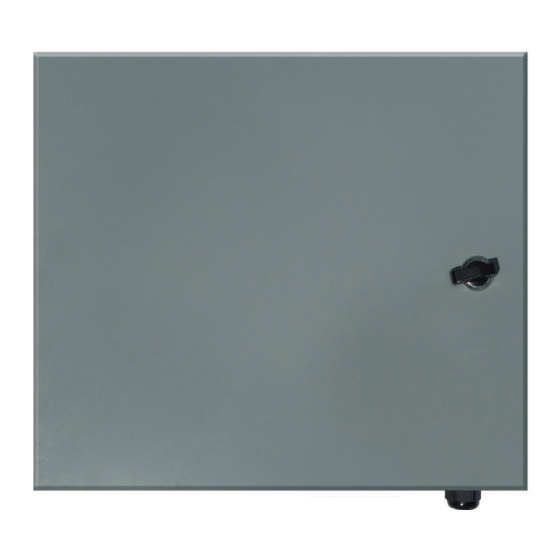
Page 1: Power Supply
Installation & Specifications Manual 2500-PWR24U 24vdc Power Supply RP8500225B N56W24720 N. Corporate Circle Sussex, WI 53089 Made in the USA Ver. 6 800-451-1460 www.RATHCommunications.com 3 Year Warranty 12/18... - Page 2 Thank you for purchasing RATH’s 2500-PWR24U Power Supply. We are the largest Emergency Communication Manufacturer in North America and have been in business for over 35 years. We take great pride in our products, service, and support. Our Emergency Products are of the highest quality.
- Page 3 Wiring methods shall be in accordance with NFPA 72 and with all local codes and Authorities Having Jurisdiction. 1. Mount the 2500-PWR24U in the desired location near the power source and power runs for the devices. a. Mark and predrill holes in the walls to line up with the top two keyholes in the enclosure (Fig. 8, pg. 6).
- Page 4 Note: A three-prong plug is included with the 2500-PWR24U. Note: The 2500-PWR24U is enabled with DC Fail Supervision using contact closures which indicate loss of DC power. Example: The contact closures can be connected to an annunciator alarm panel (Fig. 7, pg. 4). The relay is normally energized when DC power is present.
-
Page 5: Specifications
Negative DC power outputs Maintenance Under normal conditions, the 2500-PWR24U should be checked for proper operation annually. It is recommended to check the output voltage and verify that 24vdc is present under normal load conditions. It is also recommended to check the current draw to ensure that the current is within specifications. - Page 6 Mounting 2.81” 2.81” 12.29” 12.29” 2.81” 2.81” 10.50” 10.5” FIG. 9 FIG. 8 7.00” 8.78” 7” 8.78” FIG. 9 FIG. 10 Page 6...
Need help?
Do you have a question about the 2500-PWR24U and is the answer not in the manual?
Questions and answers
the terminals that wires go to on the power supply, what is the torque value?