Table of Contents
Advertisement
User Manual
Installation
Industrial ETHERNET Firewall
EAGLE 20
EAGLE 20
1
2
P
FAULT
STATUS
LS/DA
1
2
V.24
R
k
1
USB
2
g
V.24
EAGLE 20 TX/TX
EAGLE 20
Release 09 04/2012
EAGLE 20
1
2
P
FAULT
STATUS
LS/DA
1
2
V.24
R
k
1
USB
2
g
V.24
EAGLE 20 TX/MM
EAGLE 20 TX/SM
EAGLE 20
1
2
P
FAULT
STATUS
LS/DA
1
2
V.24
R
k
1
USB
2
g
V.24
EAGLE 20 MM/TX
https://hirschmann-support.belden.eu.com
EAGLE 20
1
2
P
FAULT
STATUS
LS/DA
1
2
V.24
R
k
1
USB
2
g
V.24
EAGLE 20 MM/MM
Technical Support
Advertisement
Table of Contents

Related Manuals for Hirschmann EAGLE 20 TX/TX


Summary of Contents for Hirschmann EAGLE 20 TX/TX
- Page 1 FAULT STATUS STATUS STATUS STATUS LS/DA LS/DA LS/DA LS/DA V.24 V.24 V.24 V.24 V.24 V.24 V.24 V.24 EAGLE 20 MM/MM EAGLE 20 MM/TX EAGLE 20 TX/MM EAGLE 20 TX/TX EAGLE 20 TX/SM EAGLE 20 Technical Support Release 09 04/2012 https://hirschmann-support.belden.eu.com...
- Page 2 In addition, we refer to the conditions of use specified in the license contract. You can get the latest version of this manual on the Internet at the Hirschmann product site (www.hirschmann.com). Printed in Germany Hirschmann Automation and Control GmbH Stuttgarter Str.
-
Page 3: Table Of Contents
Contents Safety instructions About this manual Device description General device description Description of the device variants 1.2.1 Device variants with 2 TX ports 1.2.2 Device variants with 1 TX port and 1 FX port 1.2.3 Device variants with 1 FX port and 1 TX port 1.2.4 Device variants with 2 FX ports Assembly and start-up Installing the device... -
Page 4: Safety Instructions
Safety instructions Important Information Notice: Read these instructions carefully, and look at the equipment to become familiar with the device before trying to install, operate, or maintain it. The following special messages may appear throughout this documentation or on the equipment to warn of potential hazards or to call attention to information that clarifies or simplifies a procedure. - Page 5 Certified usage The device may only be employed for the purposes described in the catalog and technical description, and only in conjunction with external devices and components recommended or approved by the manufacturer. The product can only be operated cor- rectly and safely if it is transported, stored, installed and assembled pro- perly and correctly.
- Page 6 Housing DANGER HAZARD OF ELECTRIC SHOCK Never insert sharp objects (small screwdrivers, wires, etc.) into the inside of the product. Failure to follow these instructions will result in death, serious injury, or equipment damage. CAUTION EQUIPMENT OVERHEATING When installing the device, make sure any ventilation slots remain free. Maintain a clearance of at least 10 cm (3.94 in).
- Page 7 Qualification requirements for personnel Qualified personnel as understood in this manual and the warning signs, are persons who are familiar with the setup, assembly, startup, and operation of this product and are appropriately qualified for their job. This includes, for example, those persons who have been: ...
- Page 8 In accordance with the above-named EU directive(s), the EU conformity declaration will be at the disposal of the relevant authorities at the following address: Hirschmann Automation and Control GmbH Stuttgarter Str. 45-51 72654 Neckartenzlingen Tel.: +49 1805 141538 The product can be used in the industrial sector.
- Page 9 Appropriate testing has established that this device fulfills the requirements of a class A digital device in line with part 15 of the FCC regulations. These requirements are designed to provide sufficient protection against interference when the device is being used in a business environment. The device creates and uses high frequencies and can radiate same, and if it is not installed and used in accordance with this operating manual, it can cause radio transmission interference.
-
Page 10: About This Manual
About this manual The “Installation” user manual contains a device description, safety instructions, a description of the display, and the other information that you need to install the device. The following manuals are available as PDF files on the CD-ROM supplied: ... -
Page 11: Device Description
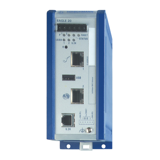
Device description General device description The industrial Firewall/VPN system EAGLE 20 TX/TX EAGLE 20 TX/MM EAGLE 20 TX/SM EAGLE 20 MM/TX EAGLE 20 MM/MM subsequently referred to as EAGLE 20, helps provide for the authentication, security and confidentiality of communication within production networks, but also beyond company boundaries. - Page 12 EAGLE 20 FAULT STATUS LS/DA V.24 V.24 Figure 1: Overview of interfaces, display and operating elements on the EAGLE 20 1 - 6-pin terminal block, pluggable 2 - LED display elements 3 - Reset button 4 - IP address field 5 - Port 1: Depending on device model, TX (RJ45 connector) and/or FX (DSC connector) 6 - USB connection...
-
Page 13: Description Of The Device Variants
The device contains the function units, such as: Firewall/VPN function, Management function, voltage connection, management connection (V.24), operation element (reset button). Interfaces Device Port 1 (INTERNAL) Port 2 (EXTERNAL) EAGLE 20 TX/TX — — — — EAGLE 20 TX/MM — —... -
Page 14: Device Variants With 2 Tx Ports
EAGLE 20 FAULT STATUS LS/DA V.24 V.24 Figure 2: Interfaces of the EAGLE 20 TX/TX 1 - Port 1 (INTERNAL port): 100BASE-TX, RJ45 connector, Autonegotiaton, autopolarity, autocrossing 2 - Port 2 (EXTERNAL port): 100BASE-TX, RJ45 connector, Autonegotiaton, autopolarity, autocrossing 1.2.2... -
Page 15: Device Variants With 1 Fx Port And 1 Tx Port
1.2.3 Device variants with 1 FX port and 1 TX port EAGLE 20 FAULT STATUS LS/DA V.24 V.24 Figure 4: Interfaces of the EAGLE 20 MM/TX 1 - Port 1 (INTERNAL port): 100BASE-FX, DSC connector, Multimode 2 - Port 2 (EXTERNAL port): 100BASE-TX, RJ45 connector, Autonegotiaton, autopolarity, autocrossing 1.2.4 Device variants with 2 FX ports... -
Page 16: Assembly And Start-Up
Assembly and start-up Installing the device Before installing and starting up the device, note the safety instructions (see page 5 onwards). 2.1.1 Overview of installation Two or more devices configured with the same IP address can cause unpredictable operation of your network. WARNING UNINTENDED EQUIPMENT OPERATION Establish and maintain a process for assigning unique IP addresses to all... -
Page 17: Terminal Block For Supply Voltage And Signal Contact
2.1.3 Terminal block for supply voltage and signal contact The supply voltage and the signal contact are connected via a 6-pin terminal block with a snap lock. Supply voltage DANGER HAZARD OF ELECTRIC SHOCK OR BURN When the module is operated with direct plug-in power units, use only: –... -
Page 18: Connecting The Terminal Block, Start-Up Procedure
FAULT +24V(P1) 0V 0V +24V(P2) 24 V AC 24 V AC Figure 7: Pin assignment of the 6-pin terminal block, AC connection Signal contacts The signal contact (“FAULT”, for pin assignment see fig. 6 fig. is used for the remote monitoring of the device to enable remote diagnostics. -
Page 19: Connecting The Data Lines
Note: The shielding ground of the industrial connectable twisted pair lines is connected to the front panel as a conductor. Figure 8: Mounting on the DIN rail Grounding The device housing is grounded by means of the separate ground screw. (see fig. - Page 20 Figure Function One line pair: receiver path One line pair: sender path 4,5,7,8 Not used Table 2: Pin assignment of a TP/TX interface in MDI-X mode, RJ45 socket 100 Mbit/s F/O connection These connections are DSC connectors. 100 MBit/s F/O ports enable the connection of terminal devices or independent network segments in compliance with the IEEE 802.3 100BASE-FX standard.
-
Page 21: Connection To The Network
2.1.7 Connection to the network Connect the device via the INTERNAL port to the internal network or the local computer that you want to help protect. Connect the device via the EXTERNAL port to the external network, e.g. the Internet. - Page 22 Device state These LEDs provide information about conditions which affect the operation of the whole device. P1 - Power 1 (green LED) Glowing green Supply voltage 1 is present Not glowing Supply voltage 1 is too low P2 - Power 2 (green LED) Glowing green Supply voltage 2 is present Not glowing...
-
Page 23: Controls
Controls The EAGLE 20 has a Reset button (see fig. Reset button R (restart) The reset button is used to restart the device. To perform the restart, press the reset button for longer than 1.5 seconds until the STATUS LED goes dark and the FAULT LED lights up red. -
Page 24: Configuration
Contact number Signal name - Data + Data Ground V.24 interface (external management) A serial interface is provided on the RJ11 socket (V.24 interface) for the local connection of an external management station (VT100 terminal or PC with corresponding terminal emulation). This enables you to set up a connection to the Command Line Interface (CLI) and to the system monitor. -
Page 25: Operating Modes
Configurable Firewall rules: Incoming/outgoing data traffic Modem access External Management access IP Masquerading, 1-to-1 NAT, Port Forwarding IP Spoofing Protection VPN functions The EAGLE 20 supports the following Virtual Private Network (VPN) functions: ... - Page 26 In the state on delivery, you can access the device via address 192.168.1.1/24 without configuring the IP address. Router Mode In Router Mode, the device works as a 2-port router. You will find a detailed description of the IP configuration in the “Configuration” user manual of the EAGLE 20.
-
Page 27: Start Configuration
2.5.3 Start configuration To access the EAGLE 20, you proceed as follows (device in state on delivery): Install the required Java plug-in on your computer. You will find information about the plug-in and its installation in the Configuration user manual. ... -
Page 28: Maintenance
Depending on the degree of pollution in the operating environment, check at regular intervals that the ventilation slots in the device are not obstructed. When designing this device, Hirschmann was largely able to forego using wear parts. The parts subject to wear are dimensioned to last longer than the lifetime of the product when it is operated normally. -
Page 29: Disassembly
Disassembly Disassembling the device In order to remove the device from the DIN rail, move the screwdriver horizontally under the chassis in the locking gate, pull this down - without tilting the screwdriver - and fold the device up. Figure 12: Disassembly EAGLE 20 Release 09 04/2012... -
Page 30: Technical Data
Technical data General technical data Dimensions EAGLE 20... 2.36 in. × 5.71 in. × 4.92 in. W × H × D (60 mm × 145 mm × 125 mm) Weight EAGLE 20... 21.16 oz - 22.22 oz (depending on variant) (600 g - 630 g) Power supply Redundant power supply... - Page 31 EMC and immunity EMC interference immunity EN 61000-4-2 Electrostatic discharge Contact discharge 4 kV Air discharge 8 KV EN 61000-4-3 Electromagnetic field 80 - 2,700 MHz 10 V/m EN 61000-4-4 Fast transients (burst) - Power line 2 kV - Data line 1 kV EN 61000-4-5 Voltage surges...
- Page 32 ...MM/MM 9.5 W 32.4 Btu (IT)/h 9.6 W 32.8 Btu (IT)/h Order numbers Device Order number EAGLE 20 TX/TX 943 987-001 EAGLE 20 TX/MM 943 987-002 EAGLE 20 TX/SM 943 987-003 EAGLE 20 MM/TX 943 987-004 EAGLE 20 MM/MM...
- Page 33 Scope of delivery EAGLE 20 device Terminal block 6-pin Connection Power supply Signal contact CD ROM with user manual Installation user manual Accessories Note: Please note that products recommended as accessories may have characteristics that do not fully comply with those of the corresponding product.
- Page 34 The device has a certification based on a specific standard only if the certification indicator appears on the housing. However, with the exception of Germanischer Lloyd, ship certifications are only included in the product information under www.hirschmann.com. EAGLE 20 Release 09 04/2012...
-
Page 35: A Further Support
Further Support Technical Questions For technical questions, please contact any Hirschmann dealer in your area or Hirschmann directly. You will find the addresses of our partners on the Internet at http://www.hirschmann.com Contact our support at https://hirschmann-support.belden.eu.com You can contact us in the EMEA region at ...
Need help?
Do you have a question about the EAGLE 20 TX/TX and is the answer not in the manual?
Questions and answers