Table of Contents
Advertisement
Quick Links
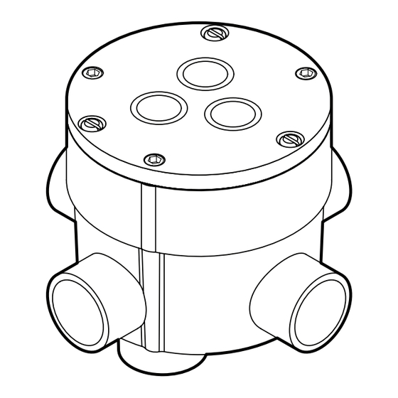
MODEL HSC-24
PAVEMENT-MOUNTED SNOW AND ICE SENSOR
DESCRIPTION
The Snow Switch Model HSC-24, 24-volt Pavement-Mounted Snow
and Ice Sensor reliably detects snow and ice conditions on pavement
surfaces. The HSC-24 pavement sensor ensures that deicing heaters
operate only while needed which minimizes energy costs without
sacrificing snow melting effectiveness.
The HSC-24 is designed to be self-contained eliminating the need for
an additional control panel, and it's independent relay-contact output is
compatible with most heater control systems.
As part of a snow melting system, the HSC–24 sensor will signal for snow
and ice melting at pavement temperatures below 38°F (3.3°C) while
moisture in any form—including water, snow, sleet or ice—is present.
South Bend, Indiana USA
|
networketi.com
DEICING CONTROLLER INSTALLATION MANUAL | PART NO.
25123
REV
0.0
Advertisement
Table of Contents

Subscribe to Our Youtube Channel
Related Manuals for ETI SNOW SWITCH HSC-24


Summary of Contents for ETI SNOW SWITCH HSC-24
- Page 1 MODEL HSC-24 PAVEMENT-MOUNTED SNOW AND ICE SENSOR DESCRIPTION The Snow Switch Model HSC-24, 24-volt Pavement-Mounted Snow and Ice Sensor reliably detects snow and ice conditions on pavement surfaces. The HSC-24 pavement sensor ensures that deicing heaters operate only while needed which minimizes energy costs without sacrificing snow melting effectiveness.
- Page 2 TRACK MOISTURE AND WET DEBRIS ONTO for inspection by the carrier. If any of the contents are THE PAVEMENT SENSOR AND CAUSE THE missing or damaged please contact your supplier or ETI SYSTEM TO RUN LONGER. DEPENDING ON Customer Service.
-
Page 3: Housing Installation
CONDUIT After positioning the sensor, install 3/4” conduit from the duct sealant until it is pliable. In addition to sealing the sensor housing to the snow melting control. Do not share wiring conduit, the duct sealant should occupy space in the sensor cable’s conduit with any high voltage wiring. - Page 4 FIGURE 1. HSC-24 Pavement Sensor Installation. FIGURE 2. Remove protective hex screw to reveal Height FIGURE 3. Rotate Height Adjustment Screw clockwise to Adjustment Screw. lower or counterclockwise to raise sensor. South Bend, Indiana USA networketi.com DEICING CONTROLLER INSTALLATION MANUAL | PART NO. 25123...
- Page 5 FIGURE 4. Wire connections for 24 ac loads. FIGURE 5. Wire connections for external relay with 24 ac coil. FIGURE 6. Wire connections for dry contact control. South Bend, Indiana USA networketi.com DEICING CONTROLLER INSTALLATION MANUAL | PART NO. 25123...
- Page 6 (the red wire). The meter can be set to DC amps when the sensor is being powered by a functioning ETI control panel. It can To call for heat, the blue and orange wires are...
- Page 7 b. As shown in Figure 7, the output and heater When the output is turned ON, the voltage from Blue temperature, measured to the nearest degree F. to Orange will be zero volts. One pulse means below 38, 2 means at 38, 3 means above 38, 4 means there is a problem.
- Page 8 FIGURE 7. Sensor Self-Test Mode. FIGURE 8. Hold-On Time Display Mode. HOLD-ON TIME DISPLAY The programmed hold time can be determined with this both the heater and output (one second on, one second off) n+1 times to indicate the currently configured hold- test.
-
Page 9: Troubleshooting
ETI Technical Support at for troubleshooting assistance. MAINTENANCE Before returning a unit to ETI, obtain a Return Merchandise The top of the sensor should be kept reasonably clean Authorization from our Customer Service Department, and free of gravel, leaves, mud, or other debris. -
Page 10: Specifications
SPECIFICATIONS General Area of Use Pavement Activation Temperature 38˚ F (3.3˚ C) Hold-on Time User configurable to 0 h, 1 h, 2 h, 3 h, 4 h, 5 h, or 6 h Default Hold-On Time 0 h up to 3 minutes after snow/ice/water no longer detected or 5 minutes after temperature rises above sense range Materials Brass with Epoxy and Polyurethane Fill... -
Page 11: Ordering Information
Web: networketi.com in this publication, without the obligation of ETI to notify Mail: ETI any person or organization of such revisions, changes or 1850 North Sheridan Street improvements.
Need help?
Do you have a question about the SNOW SWITCH HSC-24 and is the answer not in the manual?
Questions and answers