Table of Contents
Advertisement
Quick Links
Advertisement
Table of Contents

Related Manuals for kayse LS20

Summary of Contents for kayse LS20
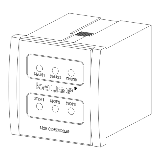
- Page 1 LS20 CONTROLLER INSTALLATION AND OPERATION GUIDE v1.00/051217 ENGLISH...
-
Page 2: Table Of Contents
LS20 CONTROLLER INSTALLATION AND OPERATING GUIDE • READ THIS DOCUMENT CAREFULLY BEFORE COMMISSIONING THE DEVICE, • ELECTRICAL CONNECTION OF THE DEVICE MUST BE MADE BY AUTHORIZED PERSONNEL OTHERWISE THERE IS DANGER OF SERIOUS INJURY OR DEATH, • THIS DOCUMENT LATER SHOULD BE KEPT IN AN EASILY ACCES- SIBLE PLACE, •... - Page 3 LS20 CONTROLLER INSTALLATION AND OPERATING GUIDE 1. GENERAL 1.1 Device Description LS20 Controller devices are the devices that can control 3 dif- ferent integrated relays by using data received from PS1x Limit Switch series, PS3x Limit Switch series or LS20 Level Control Equipments.
-
Page 4: Mounting
: 2-3 W Working Temp. : 0 +50 Storage Temp. : -40 +70 1.4 Content of the Package LS20 Controller is being shipped with terminal connections, 2 each fixing stands and this document in a carton box. 2. MOUNTING 2.1 Dimentions... - Page 5 LS20 CONTROLLER INSTALLATION AND OPERATING GUIDE 2.2 Panel Cutting Dimensions...
- Page 6 LS20 CONTROLLER INSTALLATION AND OPERATING GUIDE 2.3 Assembly Environment and the Working Conditions LS20 Controller devices should be definitely used with at least one panel protection class IP65 or by installing within the box. In contrary the oxidation can occur in the electrical equipments.
-
Page 7: Electrical Connections
LS20 CONTROLLER INSTALLATION AND OPERATING GUIDE 2.5 Assembly Sequencing Place the device to the panel that has been manufactured ac- • cording to 2.2 Panel Cutting Dimentions place the device by fac- ing the screen yourself, According to the 2.4 Mounting Type tighten the fixing stands •... - Page 8 LS20 CONTROLLER INSTALLATION AND OPERATING GUIDE 3.2 Supply Voltage Connections Energizing of device other than supply voltage tolerances may severely damage the device. At connection of devices with 220 VAC measures should be taken against electrical shock. At de- vices with 24 VDC supply voltage, the directions of -/+ poles does not different.
- Page 9 LS20 CONTROLLER INSTALLATION AND OPERATING GUIDE 3.3 Logic Input Connections In case of reversed operation, the relay inputs 'start' and 'stop' positions should be changed. For alarm applications. In alarm applications, button switch can be used instead of limit switch- es for manual stop operation.
- Page 10 LS20 CONTROLLER INSTALLATION AND OPERATING GUIDE 3.3.2 PS30 / PS31 Limit Switches Connections...
- Page 11 LS20 CONTROLLER INSTALLATION AND OPERATING GUIDE 3.3.3 LS20 Level Control Equipment Connections The drawing is given as example because LS20 Level Control Equipments are manufactured according to requests.
- Page 12 LS20 CONTROLLER INSTALLATION AND OPERATING GUIDE 3.4 Relay Output Connections Devices which draws heavy current and are coiled such pump controlled by relay outputs, solenoid valve or siren should nec- essarily be controlled in indirect way by means of auxiliary re- lay and contactor.
-
Page 13: Start Up
PS1x / PS3x Limit Switch connections to be made to logic inputs can use 2 x 0.75 mm2 cross-section cables. LS20 Level Controllers must be selected according to the number of contacts as they are custom made specifically for the application. - Page 14 "3. ELECTRICAL CONNECTIONS”. In case that LS20 Controller devices and Limit Switches such as PS1x / PS3x other than LS20 Level Controllers will be used, it may be necessary to send information to detect the level information af- ter the initial power up.
- Page 15 Level Indicator of MLG Series into the “Stop” input or (for example if pump is working and in case that it is controlled by the Relay 1 at LS20 Controller) “Start 1” input into the body of PS1x/PS3x Limit Switch in the manner almost to touch it;...
-
Page 16: Malfunction
Make sure that supply voltage reaches of the LEDs at to LS20 Controller. If the energy correctly the screen does reaches to the Controller, LS20 may be out not work even of order. Pass through article 5.3. after you made them energized;... - Page 17 LS20 CONTROLLER INSTALLATION AND OPERATING GUIDE 5.2 Determination of Sensor Defects 5.2.1 Determination of PS1x / PS3x Limit Switches Defects There is no difference between Limit Switches of PS1x and ve PS3x Series in terms of their electrical structures. Only their mechanical properties or their connection types to the MLG Series Level Indicators may vary.
- Page 18 PS1x and PS3x Series Limit Switches. Testing of the contacts is the control of switching the contacts to the closed position by moving the float on the LS20 Level Controller. When measurement is taken in Ω position of the...
- Page 19 LS20 CONTROLLER INSTALLATION AND OPERATING GUIDE 5.3 Things To Be Done Before Service In case that no solution is found even if the trouble shooting has been done as per the article “5.1”; Note the information regarding to the malfunction, •...
- Page 20 KAYSE END. MAM. SAN. TIC. A.S. Tepeoren ITOSB 7th Street No:4 34959 Tuzla ISTANBUL/TURKEY : +90 216 304 00 65 teknik@kayse.com.tr : +90 216 304 14 54 www.kayse.com.tr...
Need help?
Do you have a question about the LS20 and is the answer not in the manual?
Questions and answers