Advertisement
Advertisement

Related Manuals for kayse LS30

Summary of Contents for kayse LS30
- Page 1 LS30 CONTROLLER INSTALLATION AND OPERATION GUIDE v1.01/030913 ENGLISH...
-
Page 2: Table Of Contents
LS30 CONTROLLER INSTALLATION AND OPERATING GUIDE • READ THIS DOCUMENT CAREFULLY BEFORE COMMISSIONING THE DEVICE, • ELECTRICAL CONNECTION OF THE DEVICE MUST BE MADE BY AUTHORIZED PERSONNEL OTHERWISE THERE IS DANGER OF SERIOUS INJURY OR DEATH, • THIS DOCUMENT LATER SHOULD BE KEPT IN AN EASILY ACCES- SIBLE PLACE, •... -
Page 3: General
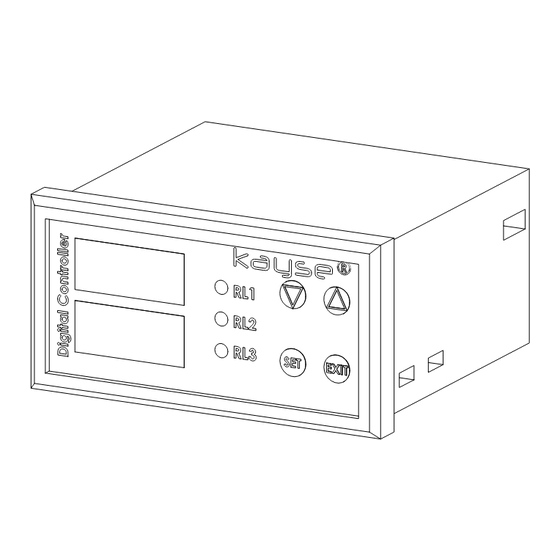
LS30 CONTROLLER INSTALLATION AND OPERATING GUIDE 1. GENERAL 1.1 Device Description LS30 Controller devices are the devices that transfer data to user and automation systems by using the data received from MLG30 and LS30 Level Control Equipments. Sensor data related with level sensors are transferred to LS30 Controller and level changes can be monitored from display screen. -
Page 4: Mounting
: 4-5 W Working Temp. : 0 +50 Storage Temp. : -40 +70 1.4 Content of the Package LS30 Controller is being shipped with connection with 2 each fixing stands and with this document within a carton box. 2. MOUNTING 2.1 Dimentions... - Page 5 IP65 or by installing within the box. In contrary the oxidation can occur in the electrical equipments. Using of LS30 Controllers in medium of big evaporation can not be recommended from the point of life cycle.
- Page 6 LS30 CONTROLLER INSTALLATION AND OPERATING GUIDE 2.4 Mounting Type 2.5 Assembly Sequencing Place the device to the panel that has been manufactured ac- • cording to 2.2 Panel Cutting Dimentions place the device by fac- ing the screen yourself, According to the 2.4 Mounting Type tighten the fixing stands •...
-
Page 7: Electrical Connections
LS30 CONTROLLER INSTALLATION AND OPERATING GUIDE 3. ELECTRICAL CONNECTIONS 3.1 Basic Electrical Connections The electricity connections of device should be made by an au- thorized electrician. In addition cable connections should be maximum 1.5 mm in cross section. In contrary terminal con- nections can not be made. - Page 8 LS30 CONTROLLER INSTALLATION AND OPERATING GUIDE 220 VAC (Fuse 12 11 10 9 According to General Load) 21 20 19 18 17 16 15 14 13 3 - 6A 24 VDC (Fuse 12 11 10 9 According to General Load)
- Page 9 LS30 CONTROLLER INSTALLATION AND OPERATING GUIDE 3.3 Sensor Connections 3.3.1 Sensor Connections for LS30 Level Control Equipments...
- Page 10 LS30 CONTROLLER INSTALLATION AND OPERATING GUIDE 3.3.2 Sensor Connections for MLG30 Level Control Equip- ments...
- Page 11 LS30 CONTROLLER INSTALLATION AND OPERATING GUIDE 3.4 Digital Input Connections Please ask for digital input connections. 3.5 Relay Output Connections Pump, solenoid valve or siren type of coiled and high current consumption devices that will be controlled with relay outputs should be definitely controlled by auxiliary relay or contactor indirectly.
- Page 12 LS30 CONTROLLER INSTALLATION AND OPERATING GUIDE 3.6 Analogue Output Connections Automation System or Monitoring Device (Input Impedance max. 500Ω) 12 11 10 9 mA Output 21 20 19 18 17 16 15 14 13 Automation System or Monitoring Device 12 11 10 9...
-
Page 13: Programming
At LS30 and MLG30 sensor input connections 3x0,75mm cross section cables can be used. - Page 14 LS30 CONTROLLER INSTALLATION AND OPERATING GUIDE 4.1 Useing the Keypad 4.1.1 'Set' Button With 'Set' button, entry to menu transition between param- eters and approval transactions can be made. For entry to menu 'Set' button is pressed until 'R1' on parameter appears on screen.
- Page 15 LS30 CONTROLLER INSTALLATION AND OPERATING GUIDE 4.2 Menu System There are 3 different menu levels for LS30 Controller program- ming. First Level Menu >2 sec. Main Op. EXIT >2 sec. Screen r.Lo r1.on r.Hi r1.oF r2.on Third Level Menu r2.oF Second Level Menu r3.on...
- Page 16 LS30 CONTROLLER INSTALLATION AND OPERATING GUIDE 4.3 General Parameters List Param- Factory Setting Range Explanation eters Settings r1.on 0-9999 Relay 1 On Value r1.oF 0-9999 Relay 1 Off Value r2.on 0-9999 Relay 2 On Value r2.oF 0-9999 Relay 2 Off Value r3.on...
- Page 17 LS30 CONTROLLER INSTALLATION AND OPERATING GUIDE 4.3.2 'r1.of' Parameter For relay 1 it is the parameter determining reset value. It de- termines at which point the devices connected to the adjust- ed value relay 1 will stop. 4.3.3 'r2.on' Parameter For relay 2 it is the parameter determining set value.
- Page 18 LS30 CONTROLLER INSTALLATION AND OPERATING GUIDE 4.3.7 'out' Parameter It is the parameter determining the type of analog output. The analog output value is being shipped adjusted at 4-20 mA at default value. In order to make transition between mA or V outputs the dip switch back of device should be replaced together with 'Output' parameter.
- Page 19 LS30 CONTROLLER INSTALLATION AND OPERATING GUIDE 4.3.9 'Lo' Parameter It is related with lower scale value of level quantity indicated at main operating screen. While liquid level is at minimum other parameter that should be written on screen is deter- mined wit this parameter.
-
Page 20: Adjustment Of Sensor Reference Values
LS30 CONTROLLER INSTALLATION AND OPERATING GUIDE 4.3.10 'Hı' Parameter It is related with upper scale value of the level indications in- dicated at main operating screen. While liquid level is at maxi- mum the value to be indicated on screen is determined with this parameter. - Page 21 For this reason before transition to this transaction preparation should be made. 5.1 Adjustment of Reference Value of LS30 Controller at LS30 Level Control Equipments When the reference values of LS30 Controller is being adjusted •...
- Page 22 Level Control Equipment The float is moved to top point 5.2 Adjustment of Reference Values of LS30 Controller at MLG30 Level Control Equipments By zooming the buoy until it contacts to sensor part (the long pipe piece that the orange junction box that cable connections are made) assembled next to MLG30 Level Control Equipment, the reference adjustments will be made.
- Page 23 LS30 CONTROLLER INSTALLATION AND OPERATING GUIDE When the reference values of LS30 Controller connected to • MLG30 Level Control Equipment are being adjusted the float within MLG30 Level Control Equipment should be removed. The float is brought closer to contact to the lower part of sen- •...
- Page 24 5.3 Adjustment of Reference Values Independent of Level Con- trol Equipments When the LS30 and MLG30 Level Control Equipments are not intervened by hand adjust the reference values as follows; By opening approximately 5-6 mm of two ends of 10 cm cable •...
- Page 25 LS30 CONTROLLER INSTALLATION AND OPERATING GUIDE 'Set' and 'Exit' buttons on LS30 Controller are pressed togeth- • er until 'r.lo' parameter appear on screen, Pres 'Set' button for a short time and 'r.hi' parameter will ap- • pear on screen, Contact the cable that had been contacted to terminal 3 pre- •...
-
Page 26: Malfunction
LS30 CONTROLLER INSTALLATION AND OPERATING GUIDE 6. MULFUNCTION In trouble shooting make sure that the floats of LS30 and MLG30 (whichever is being used with LS30 Controller) Level Control Equipments are operating accurately. The wrongly selected, that does not float or defective floats prevent you to take measure- ment (see assembly and user guide for MLG series level control equipments). - Page 27 6.4. Although the level Replace the connections of 1 and 2 ter- quantity is different minals of LS30 Controller. If you can not continuous '100' solve problem make sensor defect de- value appear at termination as per 6.3.
- Page 28 Make sure that analog output type is lish proper com- the same with your automation system. munication from If the analog output at LS30 Controller automation system has been adjusted as 'mA' no correct with analog output, data can be obtained from automation system reading 'V'.
- Page 29 LS30 CONTROLLER INSTALLATION AND OPERATING GUIDE 6.3 Determination of Sensor Defects The resistance value (Ω ohm) between each of the red, blue and black cables coming from sensor should be read. Total resist- ance value is directly proportional with sensor length and 1 cm is determined as 5 Ω.
- Page 30 LS30 CONTROLLER INSTALLATION AND OPERATING GUIDE NOTES :...
- Page 31 LS30 CONTROLLER INSTALLATION AND OPERATING GUIDE NOTES :...
- Page 32 KAYSE END. MAM. SAN. TIC. A.S. Orhanlı Orta District, Aktepe Industrial Zone No : 12/B 34956 Tuzla ISTANBUL/TURKEY : +90 216 304 00 65 teknik@kayse.com.tr : +90 216 304 14 54 www.kayse.com.tr...
Need help?
Do you have a question about the LS30 and is the answer not in the manual?
Questions and answers
Cihaza enerji verdiğim zaman Open yazarak flaş yapıyor
The Kayse LS30 flashes "Open" when powered on due to errors related to the sensor or sensor reference. This can mean that the sensor connections are not made correctly or there is a break in the cables.
This answer is automatically generated