Table of Contents
Advertisement
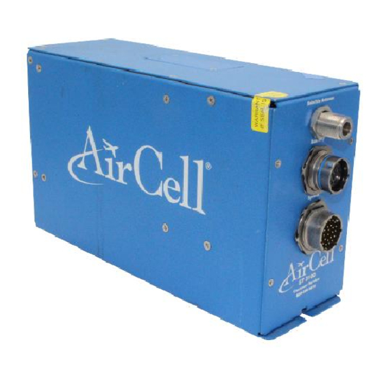
ST 3100
Installation Manual
Satellite Telephone System
Transceiver P/N 400-10680-001 and -002
Installation Manual P/N 800-10680
Revision C, May 2007
®
AirCell
LLC
1172 Century Drive, Suite 280, Building B
Louisville, CO 80027
United States of America
Distribution Statement: This publication is for the Satellite Telephone products only and is to be
®
used by Customers and authorized AirCell
agents only. Send requests for additional copies of
this document to Corporate Publications Coordinator or e-mail at (cpc@AirCell.com).
Advertisement
Table of Contents

Related Manuals for AirCell ST 3100

Summary of Contents for AirCell ST 3100
- Page 1 Distribution Statement: This publication is for the Satellite Telephone products only and is to be ® used by Customers and authorized AirCell agents only. Send requests for additional copies of this document to Corporate Publications Coordinator or e-mail at (cpc@AirCell.com).
-
Page 2: Proprietary Notice
PROPRIETARY NOTICE ® This document and the information disclosed herein are proprietary data of AirCell Neither this document nor the information contained herein shall be used, reproduced, or disclosed to others without ® written authorization of AirCell , except to the extent required for installation of recipient’s equipment. -
Page 3: Record Of Revisions
RELEASED REVISION DESCRIPTION DATE ® Original Document October 2002 AirCell Revised to delete Handset and Antenna specific ® information from this manual in order to create June 2005 AirCell separate Handset and Antenna manuals. Revised for the addition of the -002 non-POTS configuration, the functionality of revised volume ®... -
Page 4: Table Of Contents
Planning...........................3-1 3.2. Equipment Location .......................3-1 3.3. Cable Routing .........................3-2 3.4. Antenna Selection ........................3-2 3.5. Handset Selection........................3-2 3.6. ST 3100 Transceiver Location....................3-2 3.7. Power, Handset, and Audio Cabling..................3-2 3.8. Ring Detect ..........................3-2 3.9. Intercom Alert .........................3-3 3.10. Cabling.............................3-3 3.11. Satellite Antenna Installation Cable Guide ................3-4 TESTING AND SETUP ........................4-1... -
Page 5: Table Of Contents
TABLE OF CONTENTS Subject Page 5.1. Introduction ..........................5-1 5.2. Recommended Cleaning Materials ..................5-1 5.3. Procedure ..........................5-1 FITS AND CLEARANCES......................6-1 6.1. Satellite Transceiver.......................6-1 SYSTEM SPECIFICATIONS ......................7-1 7.1. Purpose............................7-1 7.2. Product Definition........................7-1 7.3. Associated Reference Documents ..................7-1 7.4. Technical Specifications......................7-1 SPECIAL TOOLS, FIXTURES, AND EQUIPMENT ...............8-1 8.1. -
Page 6: List Of Figures
Satellite Patch Antenna ....................2-4 Figure 4.1. Handset Keyboard ......................4-3 Figure 4.2. ST 3100 Transceiver (Top View) (Revision M and earlier) .........4-5 Figure 4.3. Conference Call Audio Level, Side Tone Adjustment, and Mic Bias......4-5 Figure 4.4. ST 3100 Transceiver (Top View) (Revision N and later)..........4-6 Figure 4.5. -
Page 7: List Of Tables
LIST OF TABLES Table Title Page Table 3.1. Satellite Channel RF Antenna Cable Guide ..............3-5 Page vi 800-10680-C, May 2007... -
Page 8: Introduction
The Record of Revisions, Record of Temporary Revisions, Service Bulletin List, and ® List of Effective Pages found at the front of this manual must match that issued as current by AirCell www.AirCelldealers.com will have additional information that may be useful such as,... -
Page 9: Unpacking
Louisville, Colorado 80027 Unpacking Unpack the equipment carefully to save the integrity of the shipping package. Inspect each component ® for possible shipping damage. Report any damage to AirCell immediately. Use original packing material ® to return equipment to AirCell Planning Proper and careful planning is essential for reliable system performance and ease of maintenance. -
Page 10: Advisories
® Shut off power before connecting or disconnecting the Telephone System Components (AirCell ST 3100 system), as voltage transients may damage the unit or the interface wiring. WARNING Follow the manufacturer’s safety guidelines when using any solvents, epoxies, flammable liquids, or any other materials during the installation processes. - Page 11 This Page Intentionally Blank Introduction Page 1-4 Section 1 800-10680-C, May 2007...
-
Page 12: Description And Operation
® The AirCell ST 3100 Satellite system provides both voice and data transfer options. The system enables telephone communications when the aircraft is on the ground or in the air via satellite, plus the option to have multiple handsets in the aircraft for conference-type calls. -
Page 13: Description And Overview
Mount the Handset and Cradle in any position; however, the assembly does contain a small internal magnet, so be aware of its possible affect ® on aircraft instruments and compass systems. Verify compass system deviation after the AirCell ST 3100 system installation is complete. Description and Operation... -
Page 14: Satellite Transceiver And Mounting Tray
Figure 2.5. ST 3100 Transceiver Mounting Tray The Mounting Tray is alodine-processed aluminum (Chem Film per MIL-C-5541, class 3 or equivalent) to reduce the possibility of corrosion and to provide a stable grounding path. Four (4) #6 fasteners (i.e. MS 35206-229) are used to secure the tray to the aircraft structure. -
Page 15: Satellite Patch Antenna (Standard Antenna Shown)
Note ST 3100 part number 400-01680-001 has a Plain Old Telephone System (POTS) interface and the 400-10680-002 has no POTS interface. These transceivers are identical including revision levels; the only exception is the -002 configuration lacks a POTS module installed on the motherboard. -
Page 16: Installation Procedures
Note ST 3100 part number 400-01680-001 has a Plain Old Telephone System (POTS) interface and the 400- 10680-002 has no POTS interface. These transceivers are identical including revision levels; the only exception is the -002 configuration lacks a POTS module installed on the motherboard. -
Page 17: Cable Routing
® below 3.0 dB from the AirCell ST 3100 Transceiver to the Satellite Antenna and loss less than 3.0 dB from satellite antenna to Transceiver are major considerations. This requirement is to ensure the best overall system performance. Refer to Table 3.1 to properly select the coax cables required to meet these requirements. -
Page 18: Intercom Alert
Good installation practices will ensure maximum performance from the ST 3100 System. FAA AC 43.13- 2A (Acceptable Techniques, and Practices - Aircraft Alterations), Chapter 2.27, and FAA AC 43.13-1B (Acceptable Methods, Techniques, and Practices), Chapter 11 provide excellent guidelines to ensure a good installation. -
Page 19: Satellite Antenna Installation Cable Guide
Additional handsets may be wired in parallel per handset circuit, but volume loading will occur and volume adjustment at the ST 3100 Transceiver may be required. The wiring diagram in Section 10.0 provides wiring definitions for the Audio Panel, Handsets, and RS-232 connections. Multiple RS-232/Modem connectors are allowed, but only one (1) data appliance can be connected at a time, to prevent appliance malfunction. - Page 20 should not exceed 3.0 dB @ 1600 MHz and the VSWR should be less than 1.4:1, when the cable is terminated in a 50-ohm load. Refer to Section 10.0, ICD 655-01680 (Wiring Diagrams). Low-loss 50-ohm cable should be used for this interface. Three (3) recommended Vendors are: Vendors Phone 1-800-742-3191...
- Page 21 This Page Intentionally Blank Installation Procedures Page 3-6 Section 3 800-10680-C, May 2007...
-
Page 22: Testing And Setup
After verifying that the DC power inputs are on ® the proper power pins, pull open the circuit breaker and connect the power cable to the AirCell ST 3100 Transceiver. Close the circuit breaker. -
Page 23: Maintenance And Continued Airworthiness
® . Return the Transceiver to is required for all repairs or exchanges on items returned to AirCell the factory for repair and return or call Customer Service and request that a serviceable unit be sent to you before removing the installed unit. After factory repair or receiving the serviceable Transceiver, consult the Installation Manual (800-10680) for post-installation checkout and procedures to verify proper system operation in the aircraft and correct phone numbers. -
Page 24: Telephone Operations (Standard Handset Shown)
(USA/Canada=1), then the balance of the phone number. ® Example: 9 + 1 303 379 0278 SND, this will call AirCell Customer Service. To receive a call, lift the Handset out of the cradle and press SND. -
Page 25: System Check Out
System Check Out ® The AirCell ST 3100 system can be checked out while the aircraft is on the ground or if the aircraft is outside (clear view of sky). Lift the Handset from the cradle and observe the following: •... -
Page 26: Figure 4.2. St 3100 Transceiver (Top View) (Revision M And Earlier)
These adjustments change the audio level out of the Audio Panel (A/P). ® The AirCell ST 3100 Transceiver also provides a microphone bias level through the Audio Panel. This is an ON/OFF Bias logic function enabled by a jumper. Testing and Setup... -
Page 27: Audio Level Adjustments (Revision N And Later)
Audio Level Adjustments (Revision N and later) Handset Volume Trim Level, Audio Panel Side Tone Adjustment, and Mic Bias 1. The ST 3100 audio level adjustments are set by the factory to mid-range and in most installations ® will not need to be altered in the field. -
Page 28: Figure 4.5. Handset Volume Audio Level, Side Tone Adjustment, And Mic Bias
® The AirCell ST 3100 Transceiver incoming audio adjustment allows Handset A, B and C to be independently adjusted using the 14-turn potentiometer. The factory sets the 14-turn potentiometers to a mid-range setting and in most installations will not need adjustment in the field. These adjustments are minor volume adjustments that don’t adjust from a minimum to a maximum volume level. - Page 29 This Page Intentionally Blank Testing and Setup Page 4-8 Section 4 800-10680-C, May 2007...
-
Page 30: Cleaning
CLEANING 5.1. Introduction The appearance of a completed installation is an important aspect of Customer satisfaction. Finger prints, smudges, wire clippings, and metal shavings should all be removed before the Customer inspects your work. Vacuum the affected area and clean the surrounding area completely. 5.2. - Page 31 This Page Intentionally Blank Cleaning Page 5-2 Section 5 800-10680-C, May 2007...
-
Page 32: Fits And Clearances
604-10680) provide additional installation instructions for the ® ® AirCell ST 3100 system. In addition to general notes, the attached sheets include the AirCell ST 3100 Transceiver and mounting provision dimensions, a connector pin-out orientation diagram, and access door details (potentiometer adjustments). - Page 37 This Page Intentionally Blank Fits and Clearances Page 6-2 Section 6 800-10680-C, May 2007...
-
Page 38: System Specifications
Product Definition ® The AirCell ST 3100 system utilizes the 400-10680-001 or 400-10680-002 (without POTS) ST 3100 Satellite Transceiver and is intended for aircraft applications requiring subscriber interface to the Iridium Satellite network. The integral modem provides data communication through an RS-232 port for computers and avionics equipment. - Page 39 ® • Transmit Peak: The AirCell ST 3100 Transceiver is a pulsed mode system. The duty cycle of the transmitter is 8.3 msec per 90 msec, or just under 10%. • Transceiver Heaters: When the temperature on the inside of the Transceiver is < -20C / -4F, the heaters will turn on.
- Page 40 Ring Detector.........One second ON -Three seconds OFF for incoming calls Continuous for duration of Intercom Alert Current capability......2 Amperes DC (SINK only) Voltage, withstand ......60 VDC Intercom Alert........Requires closure to ground to activate Ring Detector for duration of switch closure Audio Panel Interface Transmit Mic Bias Voltage ......+6VDC (ON/OFF selectable with jumper) Transmit Mic Input Level ......100 millivolt (mV)
- Page 41 This Page Intentionally Blank System Specifications Page 7-4 Section 7 800-10680-C, May 2007...
-
Page 42: Special Tools, Fixtures, And Equipment
SPECIAL TOOLS, FIXTURES, AND EQUIPMENT 8.1. Introduction ® No special tools are required for the installation of the AirCell ST 3100 system. 8.2. Test Setup and Calibration Refer to Section 4.0, Testing and Setup, for the procedure to verify that the unit is serviceable. - Page 43 This Page Intentionally Blank Special Tools, Fixtures, and Equipment Page 8-2 Section 8 800-10680-C, May 2007...
-
Page 44: Parts List
9.2. Parts List ® The AirCell ST 3100 kit is comprised of the following items: 400-10680-001........Satellite Transceiver w/Modem 400-10680-002........Satellite Transceiver w/Modem (without POTS) MS3126F16-26S ........Connector, Circular, 26 position (socket contacts included - crimp) 800007-1 ..........Mounting Tray, 3/8 ATR... - Page 45 This Page Intentionally Blank Illustrated Parts List Page 9-2 Section 9 800-10680-C, May 2007...
-
Page 46: 10.0 Wiring Diagrams
Drawing 655-10680) provide additional installation instructions for the ® AirCell ST 3100 system. In addition to general notes, the attached sheets include wiring diagrams for the single channel system. The Notes and Tables on these pages are very important, study them carefully. - Page 56 This Page Intentionally Blank Wiring Diagrams Page 10-2 Section 10 800-10680-C, May 2007...
-
Page 57: Wiring Diagrams
If all system connections are correct, then switch the ‘dead’ handset with a Bad handset most handsets are known good handset and retest the system. If the handset is still dead in the new location, then the handset is bad. Contact AirCell Technical Support for handset repair/replacement instructions. illuminated.) If the known good handset is now dead, then the problem is in the system wiring/connections between the handset and the Transceiver. - Page 58 The user is not authorized to open or modify sealed Enter. Line Replaceable units (LRUs). This will show a snapshot of If these steps do not resolve the problem, contact AirCell Technical Support satellite Signal. “+CSQ: X” for additional guidance. X=bars of signal.
-
Page 59: Appendix B: Instructions For Continued Airworthiness
. After obtaining an RMA return the ® AirCell ST 3100 components to the factory for repair. If you require a loaner unit to maintain telecommunications operation during ® AirCell repairs, please call Customer Service and request that a serviceable unit be sent to you before removing the installed unit. After factory repair or receiving the serviceable component, consult the Installation Manual (800-10680) for Post Installation Checkout and Procedures to verify proper system operation in the aircraft.
Need help?
Do you have a question about the ST 3100 and is the answer not in the manual?
Questions and answers