Table of Contents
Advertisement
Peter
Sinkiw
skij
Date: 2017.11.02 08:58:39 -04'00'
ou=Headquarters, email=peter@pneumercator.com, c=US
DN: cn=Peter Sinkiwskij, o=Pneumercator Co., Inc.,
Digitally signed by Peter Sinkiwskij
This document describes the installation and setup of the MODBUS RTU RS-485 Interface Card,
P/N 900552-x. Also provided are communications protocol and register mapping used to interface from
the TMS/LC2000 console to a host or master computer system supporting MODBUS RTU protocol.
Communications is over a half duplex, single twisted-pair RS-485 cable. Information available from the
TMS/LC2000 includes continuous tank data and tank-related alarms, leak/point level sensor statuses
and contact closure input statuses. The MODBUS Communications Card includes dipswitches for slave
address and baud rate selection, and provides LED indicators for transmit and receive activity. See
Section 3.0 Product Specifications for details.
MODBUS RTU Instruction Manual - 2017-11-02.docx
INSTRUCTION MANUAL
MODBUS RTU INTERFACE CARD
TMS SERIES AND LC2000 SYSTEMS
FOR
DWG NO. 20198 REV. N/C
Page 1 of 14
November 2, 2017
Advertisement
Chapters
Table of Contents

Subscribe to Our Youtube Channel
Summary of Contents for Pneumercator MODBUS RTU RS-485
- Page 1 TMS SERIES AND LC2000 SYSTEMS DWG NO. 20198 REV. N/C This document describes the installation and setup of the MODBUS RTU RS-485 Interface Card, P/N 900552-x. Also provided are communications protocol and register mapping used to interface from the TMS/LC2000 console to a host or master computer system supporting MODBUS RTU protocol.
-
Page 2: Installation And Setup
IMPORTANT! Confirm that the installed TMS console firmware version supports Modbus RTU protocol. Modbus RTU support is provided with the following TMS console firmware versions; Vxx.99.9A or later (wired) V1x.xx.04 or later V2x.00.05 or later (wired) V3x.00.05 or later (wired) where “x”... -
Page 3: Dip Switch Settings
1.1 Dip Switch Settings 1.1.1 Table Set #1 – (Rev. E and earlier, 4 Dip Switches) Slave SW #3 SW #2 SW #1 Device Address Address MSB Address 2SB Address LSB CLOSED* CLOSED* CLOSED* CLOSED CLOSED OPEN CLOSED OPEN CLOSED CLOSED OPEN OPEN... - Page 4 1.2 Installation of MODBUS Card WARNING! Turn power OFF before installing or removing any circuit cards. PROCESSOR CARD MODBUS CARD MODBUS CARD MAIN MAIN BOARD BOARD STANDOFF ON/OFF SWITCH ON/OFF SWITCH (SEE WARNING) (SEE WARNING) (SYSTEM ENCLOSURE PARTIALLY SHOWN) (SYSTEM ENCLOSURE PARTIALLY SHOWN) DWG NO.
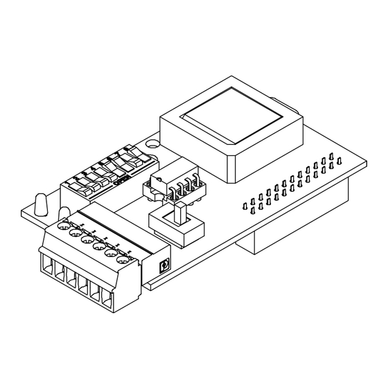
- Page 5 1.3 Terminal Connections Plug-in terminal block TB1 is provided for connection to the RS-485 Modbus. Note that both input and output terminals are provided to support multi-drop wiring. B(-) A(+) B(-) A(+) 1.3.1 Cabling Cable type should be twisted pair, shielded, and designated for RS-485 communications having a nominal impedance of 120 ohms.
-
Page 6: Led Indicators
1.3.2 Line Termination Resistor The RS-485 bus requires that the end-of-run device be terminated with a 120-ohm resistor. This is accomplished by setting the LINE TERMINATION switch to “ON” if the MODBUS Interface Card is the last device on the bus. Otherwise this switch should be set to “OFF”. END-OF-RUN MODBUS CARD MODBUS CARD... - Page 7 2.0 MODBUS Function Format Function Code 3: Read Holding Registers Note: All Queries are in Hex RTU format Master to Slave (TMS/LC2000) Query – Read TMS/LC2000 Data CHAR # Error Check - 16-bit CRC Number of Points to Read Start Address Function Code (03H) Slave Address (00H - 0FH) Slave (TMS/LC2000) to Master Response –...
- Page 8 2.1 TMS/LC2000 Data Register Map Register Address Data Group 40001 MODBUS Status Register 40002- 40017 Tank 1 40018- 40033 Tank 2 40034- 40049 Tank 3 40050- 40065 Tank 4 40066- 40081 Tank 5 40082- 40097 Tank 6 40098- 40113 Tank 7 40114- 40129 Tank 8 40130- 40145...
-
Page 9: Tank
2.1.2 Tank Data Register Detail Tank Register Start Address “T” = ((N – 1) 16) + 40002, where N = Tank Number 1 thru 12 Note: Tank Data Registers do not apply to the LC2000 since it does not interface with level probes. Register Description “T”... -
Page 10: Tank
Table #1 Status Pos. Wired Systems Wireless Systems Delivery in Progress (LSB) Probe Sync Error Probe Level Error Probe Timeout Error In-Tank Leak Test in Progress Pump/Generator Run Ullage Mode LSB (See table below) Ullage Mode MSB (See table below) In-Tank Product Motion (Note: Active LOW) No Monthly Leak Test Warning Product Below Gaugeable Level... -
Page 11: Tank
Table #2 Status Pos. Wired Systems Wireless Systems Delivery in Progress (LSB) Probe Sync Error Probe Level Error Probe Timeout Error In-Tank Leak Test in Progress Pump/Generator Run Ullage Mode LSB (See table below) Ullage Mode MSB (See table below) In-Tank Product Motion (Note: Active LOW) No Monthly Leak Test Warning Product Below Gaugeable Level... -
Page 12: Sensors
2.1.3 Sensor Data Register - Sensor Number Detail Register DB15-12 DB11-8 DB7-4 DB3-0 40194 Sensor #1 40195 40196 40197 40198 40199 40200 40201 40202 40203 Sensor #40 2.1.3.1 Sensor Data Register - Status Detail Status Normal Alarm Fault, Short Circuit 0 Fault Open Circuit Product Alarm* Water Alarm*... - Page 13 2.1.4 Contact Closure Data Register - CC Number Detail DB15-12 DB11-8 DB7-4 DB3-0 Register 40204 40205 40206 40207 2.1.4.1 Contact Closure Data Register - Status Detail Status Not Active Active, Relay Control 0 Active, Gate Control Active Alarm Active Acknowledge Not Enabled MODBUS RTU Instruction Manual - 2017-11-02.docx Page 13 of 14...
-
Page 14: Product Specifications
3.0 Product Specifications Communications Protocol: Modbus RTU Communications Format: RS-485, Half-Duplex Connection Type: Plug-In Terminal Block with Wire Entries Input: Ch. A (+), Ch. B (-), Shield Output: Ch. A (+), Ch. B (-), Shield Recommended RS-485 Cable: Belden 9841 (PVC Jacket), 89841 (FEP Teflon Jacket) or similar Maximum Cable Length: 4000 Feet/1200 Meters total to end of run LED Indicators: TX (Slave Transmit), RX (Global Receive) Serial Data Format: Fixed, 1 Start Bit, N-8-1...
Need help?
Do you have a question about the MODBUS RTU RS-485 and is the answer not in the manual?
Questions and answers