Table of Contents
Advertisement
Quick Links
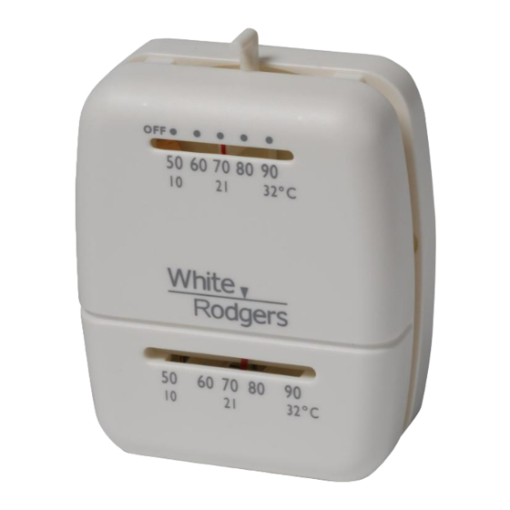
Installation Instructions for
Model M30
YOUR THERMOSTAT REPLACES
Description
Standard Heating & Cooling Systems - 4 or 5 wires
Standard Heat Only Systems
Millivolt Heat Only Systems - Floor or Wall Furnaces
Standard Central Air Conditioning
Gas or Oil Heat
Electric Furnace
Hydronic (Hot Water) Zone Heat - 2 Wires
Hydronic (Hot Water) Zone Heat - 3 Wires
Heat Pump
Baseboard Electric Heating or Line Voltage
(120 or 240 Volt)
2
THERMOSTAT FEATURES
ANTICIPAT OR
MOUNTING SCREWS
BASE
COVER
Adaptor Plate
Figure 1.
CONTENTS
Preparations ...........................................
Thermostat Features ..............................
Removing Old Thermostat ......................
Mounting and Wiring ...............................
Set Heat Anticipator ................................
New Thermostat Operation .....................
Specifications .........................................
Troubleshooting ......................................
1
PREPARATIONS
Assemble tools required as shown below.
No
Yes
Yes
No
HAND OR POWER
DRILL WITH 3/16 INCH
Yes
DRILL BIT, IF NEEDED
Yes
Yes
No
Failure to follow and read all instructions carefully before
No
installing or operating this control could cause personal
No
injury and/or property damage
3
REMOVING OLD THERMOSTAT
To prevent electrical shock and/or equipment damage,
disconnect electrical power to the system at the main fuse
or circuit breaker until installation is complete.
Before removing wires from old thermostat's switching subbase, label
each wire with the terminal designation it was removed from.
1. Remove Old Thermostat: A standard heat thermostat consists
of two basic parts:
a. The cover, which may be either a snap-on or hinge type.
b. The base, which is removed by unscrewing the mounting
screws that hold it on the wall or adaptor plate.
Make a note here
old thermostat for future reference and use in step 5.
The heat anticipator pointer, if adjustable, will be set at one of a series
of numbers representing the current rating of the primary control in
your furnace. The number will be one of the following: .2, .4, .8, etc.
or 0.2, 0.4, 0.8, etc.
If no heat anticipator/indication is showing, do not be concerned;
move on to the next step.
FLAT BLADE SCREWDRIVER
WIRE CUTTER/STRIPPER
CAUTION
!
of the anticipator setting on the
PART NO. 37-7270B
1
2
3
4
5
6
7
8
1546
Advertisement
Table of Contents

Related Manuals for White Rodgers M30


Summary of Contents for White Rodgers M30
-
Page 1: Removing Old Thermostat
CONTENTS Preparations ........... Thermostat Features ......Removing Old Thermostat ...... Mounting and Wiring ....... Installation Instructions for Set Heat Anticipator ........ Model M30 New Thermostat Operation ..... Specifications ......... Troubleshooting ........YOUR THERMOSTAT REPLACES PREPARATIONS Description Assemble tools required as shown below. -
Page 2: Mounting And Wiring
REMOVING OLD THERMOSTAT MOUNTING AND WIRING CONTINUED FROM FIRST PAGE WARNING ATTENTION! This product does not contain mercury. However, this product may replace a unit which contains mercury. Do not use on circuits exceeding specified voltage. Higher Do not open mercury cells. If a cell becomes damaged, do not touch voltage will damage control and could cause shock or fire hazard. -
Page 3: Troubleshooting
TROUBLESHOOTING Symptom Possible Cause Corrective Action No Heat 1. Blown fuse or tripped circuit breaker. Replace fuse or reset breaker. 2. Furnace power switch to OFF. Turn switch to ON. 3. Furnace blower compartment door or Replace door panel in proper position to engage panel loose or not properly installed. - Page 4 White-Rodgers is a division of Emerson Electric Co. www.white-rodgers.com...
Need help?
Do you have a question about the M30 and is the answer not in the manual?
Questions and answers