
Subscribe to Our Youtube Channel
Related Manuals for Cambium Networks cnReach N500

Summary of Contents for Cambium Networks cnReach N500
- Page 1 User Guide cnReach™ N500 System Release: 01-30 (900 MHz, 700 MHz, 450 MHz, 220 MHz)
-
Page 2: Default Login Information
Quick Start One-Page Reference Current Software Version This user guide reflects system release 01-20 containing the following software versions which can be downloaded from the Cambium Networks support website: https://support.cambiumnetworks.com/files/n500/ OS firmware: cn-EBX.5.2.17d_update Radio firmware: rf_1.48.17487-450jumbo (for both 450 MHz FCC and 450 MHz ETSI RED models) rf_1.48.17487-700g2... - Page 3 Accuracy While reasonable efforts have been made to assure the accuracy of this document, Cambium Networks assumes no liability resulting from any inaccuracies or omissions in this document, or from use of the information obtained herein. Cambium reserves the right to make changes to any products described herein to improve reliability, function, or design, and reserves the right to revise this document and to make changes from time to time in content hereof with no obligation to notify any person of revisions or changes.
-
Page 4: Table Of Contents
Cautions ....................................xv Notes ..................................... xv Caring for the environment ..............................xvi Chapter 1: Product Description ..........................1-1 cnReach System ..................................1-2 cnReach N500 Radio Modules ..........................1-4 Accessories ..................................1-7 Antennas .................................... 1-10 cnMaestro ..................................1-14 LINKPlanner ..................................1-16 Chapter 2: System Configuration ........................ - Page 5 N500 User Guide Product Description Radio/Network Settings (Full Configuration Mode)..................2-22 Auto-Configuration Mode ............................2-32 Radio/Seamless Serial Map ............................. 2-34 Serial Menu ....................................2-35 Serial/Local Serial Settings ............................2-35 Serial/Serial Services ..............................2-36 Seamless Serial Service ............................. 2-42 Serial/Modbus Bridging ............................2-43 cnMaestro Menu ..................................
- Page 6 N500 User Guide Product Description Point to Multi-Point (PMP) ............................3-2 Transmit Power and RSSI ............................3-3 Transmit Rates ................................3-6 Adaptive Modulation ..............................3-7 Frequency Hopping (900 MHz ISM Only) ......................3-7 Access Point Synchronization ..........................3-9 Max Payload Bytes ............................... 3-15 Dynamic Payload................................
- Page 7 N500 User Guide Product Description Creating a Simple Point-to-Point Link ........................... 4-6 Identical Radio Settings .............................. 4-6 Setting up a Simple PMP Network ..........................4-10 Identical Radio Settings .............................. 4-11 Unique Radio Settings ..............................4-11 Notes for Bench Testing ..............................4-12 Using the Status LEDs for Diagnostics .........................
- Page 8 Compliance with safety standards ..........................6-13 Human exposure to radio frequency energy ....................6-14 Compliance with radio regulations ..........................6-18 Type approvals................................6-18 Cambium Networks end user license agreement ....................6-20 Third party software ................................6-24 phn-4673_003v000 (November 2018) viii...
-
Page 9: About This User Guide
N500 User Guide Product Description About This User Guide This guide contains the following chapters: • Chapter 1: Product Description An overview of cnReach with model numbers, descriptions of accessories, etc. • Chapter 2: System Configuration A page-by-page walkthrough of the GUI with explanations and recommendations for each setting. -
Page 10: Purpose
Cambium Networks disclaims all liability whatsoever, implied or express, for any risk of damage, loss or reduction in system performance arising directly or indirectly out of the failure of the customer, or anyone acting on the customer's behalf, to abide by the instructions, system parameters, or recommendations made in this document. -
Page 11: Important Regulatory Information
N500 User Guide Product Description Important regulatory information Legal and Regulatory Information Refer to Chapter 5: phn-4673_003v000 (November 2018) -
Page 12: Problems And Warranty
Cambium’s standard hardware warranty is for one (1) year from date of shipment from Cambium Networks or a Cambium distributor. Cambium Networks warrants that hardware will conform to the relevant published specifications and will be free from material defects in material and workmanship under normal use and service. - Page 13 N500 Dual Radio Extended Warranty, 3 Additional Years EW-E4NBN52-WW cnReach N500 Dual Radio Extended Warranty, 4 Additional Years AR-E0NBN51-WW cnReach N500 Single Radio - Upgrade to All Risks Advanced Replacement Program during 1st Year warranty AR-E1NBN51-WW cnReach N500 Single Radio - Extended Warranty and All Risks Advanced...
-
Page 14: Security Advice
To report a potential vulnerability in Cambium Networks products or report an incident involving the Cambium Networks corporate network please email us at security@cambiumnetworks.com. -
Page 15: Warnings, Cautions, And Notes
N500 User Guide Product Description Warnings, cautions, and notes The following describes how warnings and cautions are used in this document and in all documents of the Cambium Networks document set. Warnings Warnings precede instructions that contain potentially hazardous situations. Warnings are used to alert the reader to possible hazards that could cause loss of life or physical injury. -
Page 16: Caring For The Environment
N500 User Guide Product Description Caring for the environment The following information describes national or regional requirements for the disposal of Cambium Networks supplied equipment and for the approved disposal of surplus packaging. In EU countries The following information is provided to enable regulatory compliance with the European Union (EU) directives identified and any amendments made to these directives when using Cambium equipment in EU countries. -
Page 17: Chapter 1: Product Description
Chapter 1: Product Description cnReach N500 Radio Module... -
Page 18: Cnreach System
Spare power and I/O connectors • LINKPlanner A planning and deployment tool made available by Cambium Networks Easy-to-use graphical interface that integrates with Google Earth or Google Maps Provides predictions of link performance and reliability Provides a bill of materials... - Page 19 N500 User Guide Product Description Provides an installation report to simplify the installation and alignment of cnReach radios LINKPlanner can be downloaded at no cost from the Cambium Networks website at http://www.cambiumnetworks.com/linkplanner • cnMaestro Full life-cycle network management solution for networks based on Cambium Networks equipment.
-
Page 20: Cnreach N500 Radio Modules
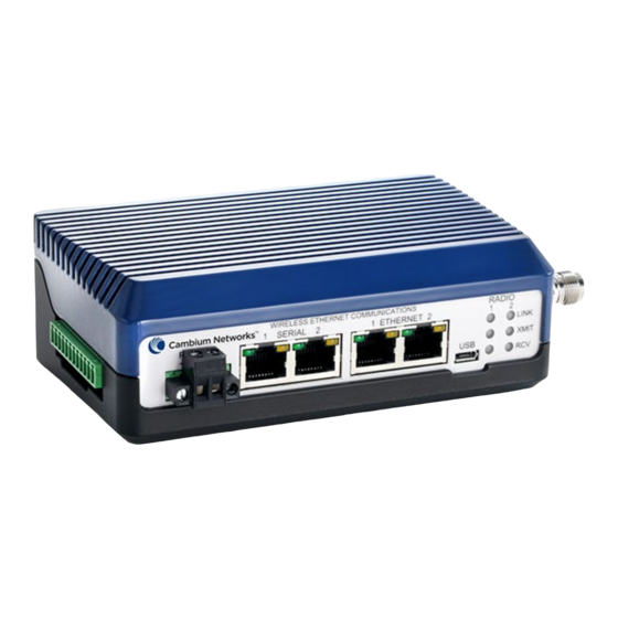
N500 User Guide Product Description cnReach N500 Radio Modules An overview of the cnReach N500 Radio Modules is provided in this section. More details are available in the technical reference section of Chapter The N500 is available in 900 MHz with the same radio supporting both MAS licensed and ISM unlicensed spectrum. - Page 21 N500 User Guide Product Description Figure 1: Front of cnReach N500 Depending on model, the right side of the enclosure will have either one or two female TNC connectors… • 1 x TNC; cnReach Single Radios. • 2 x TNC; cnReach Dual Radios.
- Page 22 N500 User Guide Product Description The table below lists the available radio modules (note the presence of single and dual modules as well as regulatory regions). Model # Model Description NB-N500910B-US N500 900 MHz Single NB-N500911B-US N500 900 MHz Single with IO...
-
Page 23: Accessories
N500 User Guide Product Description Accessories Several accessories are available for cnReach deployments. The IO expander is a cnReach module with no radios. It can be used to add Serial or Analog/Digital I/O to a broadband network or additional I/O to a narrowband network. It is managed and configured in the same way as a cnReach radio from a networking and management perspective. - Page 24 N500 User Guide Product Description Cambium offers two power supplies for cnReach. The first is an AC brick useful for bench testing or temperature controlled environments. The second is a DIN rail supply that covers a wide temperature range and is mountable in a NEMA enclosure next to a cnReach DIN mounted radio.
- Page 25 N500 User Guide Product Description NB-N500006B-US NB-N500013A-GL N500 AC to 24 VDC Power Supply with US line Power Supply, AC to 24VDC, DIN RAIL MOUNT cord NB-N500011B-GL N500 AC to 24 VDC Power Supply (no line cord) phn-4673_003v000 (November 2018)
-
Page 26: Antennas
Product Description Antennas Cambium Networks offers a range of antenna options and installation kits to assist in the deployment of a complete system. For bench testing and trials, a series of ‘whip’ low-gain omni antennas is available for each band. - Page 27 N500 User Guide Product Description Note that the 220 MHz and 450 MHz whip antennas need to be trimmed to the correct length for optimal frequency matching. An instruction sheet is included with each antenna to indicate the correct length.
- Page 28 N500 User Guide Product Description NB-N500042A-GL Yagi Antenna, 215-225 MHz, 6.5 dBd, Single Pol NB-N500029A-GL NB-N500029A-GL NB-N500044A-GL NB-N500044A-GL NB-N500045A-GL NB-N500045A-GL NB-N500053A-GL NB-N500053A-GL NB-N500046A-GL NB-N500046A-GL NB-N500030A-GL Yagi Antenna with Install Kit, 900 MHz 6.5 dBd, Single Pol NB-N500031A-GL Yagi Antenna with Install Kit, 900 MHz 10 dBd, Single Pol...
- Page 29 N500 User Guide Product Description The Yagi antennas are available either stand-alone with a two foot lead or with an integrated installation kit. For Yagis purchased with an installation kit, the antenna comes with the following items as shown in the picture below: •...
-
Page 30: Cnmaestro
(the cloud version will support cnReach by end of 2018). More information about cnMaestro and software downloads are available on the Cambium Networks website at http://www.cambiumnetworks.com/linkplanner... - Page 31 N500 User Guide Product Description Email Alarms (Q3/17) WebHooks API (Q4/17) Administration Multiple Administrators (up to 10) Role-Based Access Administrator Session Visibility Onboarding and Provisioning Zero-Touch Onboarding Template Configuration (Q4/17) Bulk Software Distribution (Q4/17) Software Update (Q4/17) Troubleshooting and Forensics...
-
Page 32: Linkplanner
Designed for use with our point-to-point and point-to-multipoint solutions, LINKPlanner allows you to easily and quickly design networks for optimal deployment and cost effectiveness. LINKPlanner is a free, easy to use link-design tool that can be downloaded from the Cambium Networks support site. Some features available for supporting cnReach deployments include: •... -
Page 33: Chapter 2: System Configuration
Chapter 2: System Configuration The system configuration chapter covers an introduction to navigating the cnReach graphical user interface. It also provides a screen-by-screen summary of each field and setting with explanations and recommendations for each setting. Keep in mind that chapter 3 provides more detailed technical reference information for some of the settings and techniques/technologies being used and chapter 4 provides some example configurations for simple example networks. -
Page 34: User Interface Overview
N500 User Guide System Configuration User Interface Overview cnReach radios can be configured using a web-based User Interface (UI). The preferred browsers are Google Chrome or Mozilla Firefox to access the user interface, but most modern browsers should work. However, due to slightly different behaviour among web-browsers it may occasionally be necessary to manually clear the cache or refresh a page or click on the link on the left navigation bar to reload a page. - Page 35 N500 User Guide System Configuration To troubleshoot these issues, open a Command Prompt Window and type ipconfig. This will give you the IP address of your computer, which should be in the same subnet (192.168.0.X) as the radio in order to communicate with the radio. On Windows-based machines, this is typically done by setting a static IP address on the Network interface being used to connect to the radio.
-
Page 36: Navigating The User Interface
N500 User Guide System Configuration Navigating the User Interface After connecting the IP address of the radio, the user will be prompted to login with a username and password. The defaults are: Username: admin Password: admin After successfully login, the home page will be displayed similar to the example below. The navigation bar is on the left and is used to connect to all of the different configuration and troubleshooting features on the radio. -
Page 37: Main Menu
N500 User Guide System Configuration Main Menu The main page is mostly used for status and configuration summary. The first four fields are free text editable by the user. Make sure to click SAVE before moving to a different page and then to click COMMIT to actually make the change take effect. - Page 38 N500 User Guide System Configuration Ethernet Firmware – displays the installed Ethernet firmware version (also referred to as the OS file in the files page) Radio Information – For modules with dual radios the information will appear as Radio 1 and Radio 2.Radio1 / Radio2 (cnReach Single/Dual 700/900 MHz radios).
-
Page 39: Network Menu
N500 User Guide System Configuration Network Menu The network menu contains features related to how the cnReach interfaces to external networking equipment and how it processes incoming packets. Network/VLANs Add and remove additional VLANs. vlan 1 is always as the primary access to the radios. The description is free-text for reference and will also appear/be editable on the Network/Interface Settings page. -
Page 40: Network/Interface Settings
N500 User Guide System Configuration Network/Interface Settings cnReach radios can be configured as either layer 2 bridges or with layer 3 statics routes. VLAN’s can also be used to determine which packets are accepted and passed at each interface. Refer to chapter 3 for more information about cnReach routing. - Page 41 N500 User Guide System Configuration Routed In this example the web interface can be accessed via the IP address of the connected interface. Routed interfaces can be assigned unique IP addresses and are required to be on different subnets. Static routes must be configured both in the radio and any connected Host for Ethernet traffic to be passed between subnets.
- Page 42 N500 User Guide System Configuration ALLOWED VLANS This value defines which VLANs are allowed to enter or leave an Interface. The default setting is 1 for VLAN1. Additional VLANs can also be allowed. VLAN Port Tagging This value controls the VLAN tagging behaviour for an Interface;...
- Page 43 N500 User Guide System Configuration Multiple VLANs can be added to the Bounce setup; Speed/Duplex Speeds of 10 Mbps, 100 Mbps or auto-negotiation (speed and duplex) can be set. Default Gateway If a Default Gateway is configured, the Radio will periodically attempt to resolve the MAC address of the default gateway via ARP.
-
Page 44: Network/Static Routes
N500 User Guide System Configuration Network/Static Routes The Static Routing feature allows for multiple subnets to be created so that only traffic destined for those subnets is Routed to those subnets, thereby eliminating unneccessary traffic on the RF links. -
Page 45: Network/Net Filters
N500 User Guide System Configuration Network/Net Filters cnReach supports an IP filtering feature used to allow only traffic coming from an approved source. The IP filter feature behaves like a ‘white list’ where The filters take action on the radio port egress traffic. -
Page 46: Radio Menu
N500 User Guide System Configuration Radio Menu The Radio menu contains all configuration parameters associated with the radio / air interface. This includes physical layer parameters like transmit power and frequency but also network topology and addressing for the air interface protocols. -
Page 47: Radio/Rf Settings
N500 User Guide System Configuration Radio/RF Settings This section describes the configuration of frequencies, transmit power, hop pattern, and transmit rates. Note cnReach radios can be used in full configuration mode or auto-configuration mode. In full configuration mode, all settings are made on all radios (APs and EPs). In auto- configuration model, the EP automatically detects many of the air interface settings from APs beacon signals. - Page 48 N500 User Guide System Configuration Licensed Band Settings (900/MAS, 700, 450, 220) If a licensed band is selected in Radio/Band settings, the following parameters are configurable: Access Point and End Point Transmit Frequencies Licensed Operation requires both the AP Tx Freq and EP Tx Freq to be manually entered. The frequencies should correspond to the frequencies and channel size issued on the FCC or other jurisdiction license.
- Page 49 N500 User Guide System Configuration Note Some older 900 MHz MAS radios have a software limit set to 3W. If your radio limits you to setting 3000 mW maximum, contact support for a patch to increase this to 4000 mW maximum.
- Page 50 N500 User Guide System Configuration The following figure showed example of a modulation modes with 50 KHz channel size. Please notice that actual modes could vary depending on firmware release.50 kHz For multi-point networks, cnReach supports multiple speeds in the EP to AP direction as selected above with transmit rates.
- Page 51 N500 User Guide System Configuration Error Correction Error correction can be set to either none, low or high. There is a trade-off in capacity and reliability in each of these settings. • Setting error correction to none does not apply any additional forward error correction.
- Page 52 N500 User Guide System Configuration Un-licensed/ISM Band Settings (900 MHz only) There are a few settings on this page that are unique to 900 MHz / ISM only. All other settings are similar to the licensed band operations above.
- Page 53 N500 User Guide System Configuration Note Care must be taken to ensure enough frequencies are available for the radio to hop within the required regulations. In particular, under FHSS rules (less than 663 Kbps) the radio must have enough frequency bandwidth as required under FCC rules;...
-
Page 54: Radio/Network Settings (Full Configuration Mode)
N500 User Guide System Configuration Radio/Network Settings (Full Configuration Mode) Note cnReach radios can be used in full configuration mode or auto-configuration mode. In full configuration mode, all settings are made on all radios (APs and EPs). In auto- configuration model, the EP automatically detects many of the air interface settings from APs beacon signals. - Page 55 N500 User Guide System Configuration Description Description is a user-definable name to permit easier identification with the RF Module frequency, network segment or RF Link. Auto-Configuration See following section on using Auto-Configuration for more details. When set to Off, the radio requires all parameters to be set on APs, EPs and REPs.
- Page 56 N500 User Guide System Configuration Device ID Device ID is a unique number that identifies the radio on the RF network. Each radio on a network, as defined by the network address, is required to have a unique ID in a similar way to IP addresses on an Ethernet network.
- Page 57 N500 User Guide System Configuration Network Radius Network Radius is the physical line-of-sight distance between two radios. It can be configured in Miles (miles) or Kilometers (km) and has an effect on transmission timing. • Setting the Network Radius larger than the actual link is acceptable.
- Page 58 External; a 1PPS “external” trigger signal from a GPS receiver is used to synchronize the 1Hz timing signal for all other radios in the network(s). See IO Connections in Chapter 3 for wiring info. The Cambium Networks uGPS is an option for providing the 1PPS sync signal. MMS Access Point Specific Settings...
- Page 59 1PPS signal to the IO connector on the side of the radio. The Cambium Networks uGPS can be used for this purpose. Either of the RJ12 – Sync ports can be used, with cable pinouts and wiring as follows;...
- Page 60 Point’s MMS setting. MMS-Dual Radio Specific Settings When using MMS with a cnReach N500 Dual Radio, the End Point radio that connects to an upstream Access Point should be set to Generate and the Access Point that has downstream End Points connected should be set to External;...
- Page 61 N500 User Guide System Configuration Max Payload Bytes Max Payload Bytes for Access Point and End Point range from 64 to 1600 Bytes with a default setting of 256. These settings are also referred to as “packet sizes”. To achieve high user data rates, larger packets and higher modulation levels are required.
- Page 62 N500 User Guide System Configuration Here is one example of the table showing how to determine the appropriate value. Make sure to use the correct table as show in Chapter 3: Technical Reference. ISM – Minimum Packet Sizes with Multi-Speed Multi-Point The following table charts the smallest “Max Payload Bytes”...
- Page 63 N500 User Guide System Configuration Dynamic Payload Dynamic payload is used to optimize the usage of the air interface. When there is no data to be sent in the uplink direction the AP can use the extra time to send more data in the downlink period. Refer to the technical reference section of this user guide for more information.
-
Page 64: Auto-Configuration Mode
N500 User Guide System Configuration Auto-Configuration Mode In Auto-configuration mode, EPs automatically retrieve many of the air interface parameters from the Access Point. In auto-configuration mode, APs send information about the air interface in the broadcast beacon. Using auto-configuration mode can dramatically reduce the complexity of configurating end points. - Page 65 N500 User Guide System Configuration The following must still be set at both AP and EP: – Auto-configure mode – Network Role – Network Address – Device ID – Link-with Device ID – Protocol – Frequencies – Transmit Power –...
-
Page 66: Radio/Seamless Serial Map
N500 User Guide System Configuration Radio/Seamless Serial Map Seamless Serial Map is used for configuring seamless serial services. The Port number is the TCP port number for seamless serial service and the radio group number is used as the identifier of the seamless serial stream. For a radio that has two radio ports, you can choose to assign the seamless service to be sent over “Radio One”... -
Page 67: Serial Menu
N500 User Guide System Configuration Serial Menu The Serial menu options relate to setting up serial services on each of the built-in serial ports on a cnReach radio. Serial/Local Serial Settings This is where the physical connection to the Serial End Device is configured. -
Page 68: Serial/Serial Services
N500 User Guide System Configuration XON/XOFF is software flow control which uses special characters to control the flow of data. The XON/XOFF characters are sent in the opposite direction to the data so the receiving device will send the characters to the sending device. XON/XOFF flow control information is sent over the same channel used for the data, therefore eliminating the requirement for extra lines in the serial connection. - Page 69 N500 User Guide System Configuration TCP Terminal Server TCP Terminal Server permits TCP connections from a Host or TCP Terminal Client to terminate on the Serial Port interface of the radio, therefore allowing Serial End Devices to communicate over the Ethernet Radio System.
- Page 70 N500 User Guide System Configuration phn-4673_003v000 (November 2018) 2-38...
- Page 71 N500 User Guide System Configuration TCP Terminal Client When set to TCP Terminal Client, activity on the Serial Port interface will initiate a TCP session to a Host or Terminal Server specified by the Remote IP address and Remote Port number in the configuration.
- Page 72 N500 User Guide System Configuration UDP Terminal The User Datagram Protocol is a connectionless protocol with less overhead than TCP. Unlike TCP, UDP does NOT guarantee delivery or delivery in order. When set to UDP Terminal, activity on the Serial Port interface will instantly encapsulate the data into a UDP datagram and send to the Host or UDP Terminal specified by the Remote IP address and Remote Port number in the configuration.
- Page 73 N500 User Guide System Configuration establish a connection. UDP datagrams arriving will be decapsulated and converted to Serial data then sent out of the Serial Port interface. The Host must be set up the same way; Remote IP, Port and also a Local Port.
-
Page 74: Seamless Serial Service
N500 User Guide System Configuration Seamless Serial Service Seamless serial is a mechanism unique to cnReach allowing for serial-only to serial-only communications within a subset of a sector (AP to a subset of it’s EPs) while sharing that same sector’s air interfaces for Ethernet traffic. -
Page 75: Serial/Modbus Bridging
N500 User Guide System Configuration The following diagram shows how seamless serial service works. Serial/Modbus Bridging The Modbus Bridging menu is used for setting up a protocol gateway between Modbus TCP (from the IP side) to Modbus RTU (at the serial side) - Page 76 N500 User Guide System Configuration To create a new Modbus TCP to RTU bridge connection: In the UI, go to Serial > Modbus Bridging. Click Add to display the bridging settings. Click the Mode list and select TCP Server or TCP Client for each part of the bridge connection. Typically, the TCP Bridge Connection is in TCP Server mode and the RTU Bridge Connection is in TCP Client mode.
- Page 77 N500 User Guide System Configuration phn-4673_003v000 (November 2018) 2-45...
-
Page 78: Cnmaestro Menu
Menu cnMaestro/Management Settings The settings on this page enable the cnReach device to be managed by the cnMaestro management system from Cambium Networks. Refer to cnMaestro documentation for setting up the server. Settings cnMaestro Management: Enable this checkbox to active cnMaestro management... - Page 79 N500 User Guide System Configuration Awaiting Authorization (cnMaestro Administrator needs to accept the module) Failed to Resolve URL (cnReach radio can’t reach cnMaestro server; URL could be incorrect) Initializing (~60 seconds) • Account ID: equates to Cambium ID entered in Settings after the connection is successfully established.
-
Page 80: I/O Menu
N500 User Guide System Configuration I/O Menu I/O/Channel Settings Built-in I/O is an optional hardware feature on cnReach models. See the product overview section for the sales models that include built-in I/O. The built-in I/O can be used to interface directly to analog and digital service (inputs and outputs). -
Page 81: I/O/Modbus Settings
N500 User Guide System Configuration I/O/Modbus Settings The Modbus communication timeout is the time the cnReach radio will wait for a new Modbus command before reverting the IO ports to their safety action. Clicking on the Modbus Register Map displays the entire register that can be read from the Modbus server. - Page 82 N500 User Guide System Configuration phn-4673_003v000 (November 2018) 2-50...
-
Page 83: I/O/Calibration Settings
N500 User Guide System Configuration I/O/Calibration Settings The I/O calibration feature allows the cnReach I/O inputs to be calibrated to real-world values. As an example, you can use the calibration field to convert analog signals from a pressure gauge to Psi units. -
Page 84: Wire-Replacement Menu
N500 User Guide System Configuration Wire-replacement Menu The wire-replacement feature enables the operator to “pass” I/O input from one cnReach as I/O output to another cnReach. One I/O input can be passed to multiple cnReach IP addresses. The wire- replacement feature is implemented by hosting a Modbus-TCP master in the cnReach. -
Page 85: Step By Step For Wire-Replacement Configuration
N500 User Guide System Configuration Analog input 4-20mA DC Flow Meter Analog output 4-20mA DC Amalog Meter (Flow Rate, Water Level) Analog input 4-20mA DC cnReach with IO cnReach with IO Water Level Meter Digital Output Dry contact Fault Lamp Operation Lamp (Pump Fault/Pump On/Off etc.) -
Page 86: Meanings For Each Field In The Wire-Replacement Configuration
N500 User Guide System Configuration Enter all the configuration parameters and hit the “Save/Commit Module Settings” button. The example above shows a wire replacement configuration that takes dry contact input from IO5 of 192.168.0.3 and generate analog output at 192.168.0.4 on IO1. -
Page 87: Wire Status
N500 User Guide System Configuration For example, 1-5V input can't be written directly to a 4-20mA output, so offset would be zero but slope would be 0.004. Wire Status The user can click on the status menu to view the status of the wires. -
Page 88: Diagnostics Menu
N500 User Guide System Configuration Diagnostics Menu cnReach has many diagnostic tools available for fine tuning and troubleshooting the network. This chapter describes each of the tools in turn. phn-4673_003v000 (November 2018) 2-56... -
Page 89: Diagnostics/Neighbor List
N500 User Guide System Configuration Diagnostics/Neighbor List The Neighbor List displays information about all the End Point Radios that are connected to an Access Point. The End Point Neighbor List will only show the Access Point unless the Bounce setting is enabled in the Access Point;... -
Page 90: Diagnostics/Rf Ping
Installing radio systems without sampling the noise floor can, in some cases, lead to unexpected performance. Cambium Networks recommends sampling the noise floor or at least making an allowance for a higher than expected noise floor in the link budget. - Page 91 Enter the Device ID for the radio on the opposing end of the link and press Ping. Note When using this utility on a cnReach N500 radio, it is necessary to select which Source Radio (RF Module) to use for the test.
-
Page 92: Diagnostics/Rf Throughput
Enter a Test Duration in seconds and press the Test button. Note When using this utility on a cnReach N500 radio, it is necessary to select which Source Radio (RF Module) to use for the test. Once initiated the link will be saturated with test packets at the RF protocol level. The link will be temporarily unavailable to normal Ethernet traffic during the test. -
Page 93: Diagnostics/Spectrum Analyzer
N500 User Guide System Configuration Diagnostics/Spectrum Analyzer The spectrum analyzer feature is designed to assist in diagnosing channel interference issues and to understand the noise floor in a given area that can be detected by the radio and its antenna. - Page 94 N500 User Guide System Configuration Configuring the Spectrum Analyzer There are several options for configuring the spectrum analyzer. Remote Radio ID selects which radio is used to ‘listen’ on for the spectrum analyzer. Radio 1 or Radio 2. Radio 2 only for dual radio modules.
- Page 95 N500 User Guide System Configuration Start. Starts the scan. Note that clicking start will cause any active link to drop and no payload traffic will Stop. Stops the scan and returns the radio to normal payload carrying operation. Moving away from this screen in the GUI will also stop the scan after a timeout period.
- Page 96 N500 User Guide System Configuration Waterfall View The waterfall view is in the lower right. This view shows the most recent result at the top and then a historical view descending towards the bottom of the screen. The x-axis is the same frequencies as shown in the RSSI view.
- Page 97 N500 User Guide System Configuration Power and Frequency Occupancy Visualizations The Occupancy visualizations show the percentage of the time that the spectrum analzyer detects each power level and each frequency respectively. The x-axis is the same as the RSSI view.
-
Page 98: Diagnostics/Network Statistics
N500 User Guide System Configuration Diagnostics/Network Statistics Network Statistics is split into two tables, both offering diagnostic information relating to Ethernet functionality; LAN and Wireless. Interface represents the interface; Ethernet 1, Ethernet 2, RF Module1, RF Module2 or any VLAN that might be configured. - Page 99 Rx Headers represents the number of RF Headers received by the RF Module. Headers are part of the cnReach N500 OTA protocol and are not part of the Ethernet Frame. Headers are used to encapsulate Ethernet frames over the air. Since Ethernet Frames can be broken up into fragments depending on the RF packet size, there can be more headers than actual Ethernet Frames.
-
Page 100: Diagnostics/Forwarding Table
N500 User Guide System Configuration Diagnostics/Forwarding Table The Forwarding Table is a dynamic table that maps device MAC addresses to ports/interfaces on the radio. It is used to identify the forwarding port/interface that the input port/interface should forward an... -
Page 101: Diagnostics/Route Table
N500 User Guide System Configuration Diagnostics/Route Table The Route Table lists the Static Routes that have been configured in the radio. Interface is the outgoing port/interface the radio will use when forwarding a packet to destination subnet or next hop. -
Page 102: Diagnostics/Serial Statistics
N500 User Guide System Configuration Flags indicate if the mac address has been learned (complete), or remains incomplete. • 0x0 incomplete • 0x2 complete Diagnostics/Serial Statistics Serial Statistics provides information on who is connected to the currently running Serial Service. -
Page 103: Diagnostics/Dns Lookup
N500 User Guide System Configuration Diagnostics/DNS Lookup DNS Lookup can be used to test the DNS server setting on the radio. Entering a fully qualified domain name will return the IP address of the host. Note that this lookup relies on a valid DNS Server setting in the Network/Interface Settings page. -
Page 104: Diagnostics/Traceroute
N500 User Guide System Configuration Diagnostics/Traceroute Traceroute performs a traditional traceroute from the cnRadio to the host identified by the IP address or hostname (if DNS servers are configured and available). It can be useful in troubleshooting radio connectivity to specific servers such as cnMaestro or a SCADA master. -
Page 105: Management Menu
N500 User Guide System Configuration Management Menu Management features include firmware updates, password management, rebooting the system and general maintenance tasks on a cnReach radio. Management / Logout Clicking this menu option immediately logs the user out of the cnReach radio. -
Page 106: Management/Administration
N500 User Guide System Configuration Management/Administration This page provides for some additional device local management such as reboot, factory reset. It also allows for booting from the alternate partition Reboot Device simply reboots the radio without changing any configuration parameters. -
Page 107: Management/Advanced Settings
N500 User Guide System Configuration Attention Resetting to factory defaults modifies both the Network and Radio settings, making it possible to lose connectivity to the device via the RF Link and/or Ethernet Port. Password changes are NOT reset to default. - Page 108 N500 User Guide System Configuration This user guide reflects the following software versions which can be downloaded from the Cambium Networks support website: https://support.cambiumnetworks.com/files/n500/ OS firmware: cn-EBX.5.2.16h_update Radio firmware: rf_1.46.15429-450 rf_1.46.15429-700g2 rf_1.46.15429-900 rf_1.46.15429-200 Attention Note that there are different radio firmware files depending on the band of the radio. The band is denoted in the filename (eg.
-
Page 109: Management/Snmp
N500 User Guide System Configuration Management/SNMP cnReach radios support SNMP V1/V2 and V3. V1/V2 requires the use of the Read Only Community String unless the SNMP Manager is required to make changes to the radio, in which case the Read Write Community String is also required. - Page 110 N500 User Guide System Configuration Trigger can be set to “level” to enable SNMP for the desired traps. Alarm Above sets the upper limit at which the radio will alarm and generate the trap notification once exceeded by the Min Fault Time.
-
Page 111: Security Menu
N500 User Guide System Configuration Security Menu Security/AES To enable AES Encryption, choose AES128 or AES256 and check Enabled on ALL radios in the network. Entering a key is optional since the radios will communicate with a zeroized key. -
Page 112: Security/Banner
N500 User Guide System Configuration Attention The key must be the same on ALL radios in the network. If the key is mismatched, the radio LED’s will appear to be linked but the radios will NOT pass Ethernet traffic. -
Page 113: Chapter 3: Technical Reference
Chapter 3: Technical Reference This chapter provides complete details of the cnReach solution including: • Radio/Air Interface Features • Networking Features • Reference tables including capacity, modulations, packet sizes, etc. per each supported radio band. 900 MHz 450 MHz 700 MHz 220 MHz •... -
Page 114: Radio/Air Interface Features
Technical Reference cnReach N500 User Guide Radio/Air Interface Features Network Role The Network Role can be one of the following: • Access Point (AP); initiates contact/communication with End Point/Repeating End Point. The Access Point is the radio that is normally connected to the Enterprise or backhaul system where access to the radio system occurs. -
Page 115: Transmit Power And Rssi
Technical Reference cnReach N500 User Guide Data may be transferred in either direction. Data transfer speeds can be manipulated using the Max Payload Bytes and Dynamic Payload settings. Refer to the section for How to set up a PTMP Network configuration information. - Page 116 Technical Reference cnReach N500 User Guide Attention RF performance is often more problematic at higher RSSI levels. When the Transmit Power is set too high, the receiving radio RSSI may be too high and the overall noise floor in the area will increase.
- Page 117 Technical Reference cnReach N500 User Guide phn-4673_002v000 (March 2018)
-
Page 118: Transmit Rates
End Point Transmit Rates ISM End Point Transmit Rates can be configured with Multi-Speed Multi-Point (MSMP). Note Cambium Networks recommends selecting a maximum for FOUR consecutive End Point Transmit Rates. Refer to ISM Minimum Packet Sizes with Multi-Speed Multi-Point for minimum packet recommendations. -
Page 119: Adaptive Modulation
When configured as part of a cnReach N500 PMP network, End Point radios are not required to communicate at the same data transmit rate. This enables remote End Point radios that are closer to the Access Point or in a better RF environment to communicate at faster data-rates than remotes that are further away or in high-noise areas. - Page 120 Technical Reference cnReach N500 User Guide Note Frequency hopping is ONLY used with 900 MHz Unlicensed/ISM bands. If the network is deployed in a licensed band, it stays on the same frequency. The hopping features described in this section are not relevant for licensed band operation Hop Channels The occupied bandwidth of the RF signal is determined by the bit rate and modulation mode that is enabled.
-
Page 121: Access Point Synchronization
Technical Reference cnReach N500 User Guide Access Point Synchronization It is common practice in large Ethernet SCADA communication systems to install multiple overlapping wireless networks to mitigate poor performance and prioritize traffic for different traffic types and mixed protocols. Wireless Ethernet networks with many remote devices can experience low throughput and long latency. - Page 122 Technical Reference cnReach N500 User Guide phn-4673_002v000 (March 2018) 3-10...
- Page 123 External; a 1PPS “external” trigger signal from a GPS receiver is used to synchronize the 1Hz timing signal for all other radios in the network(s). See IO Connections for wiring info. The Cambium Networks uGPS is an option for providing the 1PPS sync signal. Attention MMS should be configured with FHSS modulati0ns 57 MSK, 114 MSK, 153 MSK &...
- Page 124 1PPS signal to the IO connector on the side of the radio. The Cambium Networks uGPS can be used for this purpose. Either of the RJ12 – Sync ports can be used, with cable pinouts and wiring as follows;...
- Page 125 Technical Reference cnReach N500 User Guide RJ12 Pin # Signal Pinout Connect to MMS Pin # 1PPS GPS Sync 2 - 4 Not connected Ground phn-4673_002v000 (March 2018) 3-13...
- Page 126 Point’s MMS setting. cnReach Dual Radio Specific Settings When using MMS with a cnReach N500 Dual Radio, the End Point radio that connects to an upstream Access Point should be set to Generate and the Access Point that has downstream End Points the cnReach dual radio configurations have internal MMS circuitry connected should be set to External;...
-
Page 127: Max Payload Bytes
Technical Reference cnReach N500 User Guide Max Payload Bytes The Max Payload Bytes (or ‘packet size’) configuration is the key parameter to establish the size of the frame used in the air interface. The cnReach radio determines the duration of the uplink and downlink portions of the frame by combining the # of bytes in the max payload and the data rate of the maximum modulation. - Page 128 Technical Reference cnReach N500 User Guide Attention Max Payload Bytes is one of the most frequently mis-configured parameters in a cnReach and setting an invalid value will cause the link to not pass traffic. Please review this section and make sure to reference the appropriate table for the band and channel size that you are deploying.
- Page 129 Technical Reference cnReach N500 User Guide 900 MHz ISM – Minimum Packet Sizes with Multi-Speed Multi- Point The following table charts the smallest “Max Payload Bytes” setting when using multiple ISM End Point Transmit Rates. Fastest Modulation 2FSK BPSK QPSK...
- Page 130 Technical Reference cnReach N500 User Guide 25 kHz Channels Maximum Modulation Mode QPSK 8PSK 16QAM 32QAM 64QAM kbps QPSK 8PSK 16QAM 32QAM 64QAM 50 kHz Channels Maximum Modulation Mode 64QAM QPSK 8PSK 16QAM 32QAM kbps QPSK 8PSK 16QAM 32QAM 64QAM...
- Page 131 Technical Reference cnReach N500 User Guide 450 MHz FCC – Minimum Packet Sizes with Multi-Speed Multipoint 12.5 kHz Channels Maximum Modulation Mode QPSK 8PSK 16QAM 32QAM Kbps QPSK 8PSK 16QAM 32QAM 25 kHz Channels Maximum Modulation Mode QPSK 8PSK 16QAM...
- Page 132 Technical Reference cnReach N500 User Guide 450 MHz ETSI – Minimum Packet Sizes with Multi-Speed Multipoint 12.5 kHz Channels Maximum Modulation Mode BPSK QPSK 8PSK 16QAM 32QAM Kbps BPSK QPSK 8PSK 16QAM 32QAM 25 kHz Channels Maximum Modulation Mode BPSK...
- Page 133 Technical Reference cnReach N500 User Guide 700 MHz – Minimum Packet Sizes with Multi-Speed Multipoint 12.5 kHz Channels Maximum Modulation Mode QPSK 8PSK 16QAM 32QAM Kbps QPSK 8PSK 16QAM 32QAM 25 kHz Channels Maximum Modulation Mode QPSK 8PSK 16QAM 32QAM...
- Page 134 Technical Reference cnReach N500 User Guide 50 kHz Channels Maximum Modulation Mode QPSK 8PSK 16QAM 32QAM Kbps QPSK 8PSK 16QAM 32QAM 100 kHz Channels Maximum Modulation Mode QPSK 8PSK 16QAM 32QAM Kbps QPSK 8PSK 16QAM 32QAM phn-4673_002v000 (March 2018) 3-22...
- Page 135 Technical Reference cnReach N500 User Guide 200 kHz Channels Maximum Modulation Mode QPSK 8PSK 16QAM 32QAM Kbps QPSK 8PSK 16QAM 32QAM 250 kHz Channels Maximum Modulation Mode QPSK 8PSK 16QAM 32QAM Kbps 1008 QPSK 8PSK 16QAM 32QAM 1008 phn-4673_002v000 (March 2018)
-
Page 136: Dynamic Payload
Technical Reference cnReach N500 User Guide Dynamic Payload Dynamic Payload is a feature that allocates the unused portion of the Access Point’s timeslot to the End Point’s timeslot to increase throughput from End Point Access Point. 3535kbps 16QAM FBench throughput test results. -
Page 137: Networking Features
N500 Multi-Layer radios make it possible to build RF networks with data routed across multiple subnets, eliminating all unnecessary Ethernet traffic from the RF links. -
Page 138: Network/Vlans
Technical Reference cnReach N500 User Guide Network/VLANs CnReach radios function as 5-port enterprise Ethernet switches by implementing 802.1q VLANs and trunks. The five ports that participate in the Ethernet switching process are: Port / Interface Description Physical Ethernet interface which can function as an access port, an Ethernet 1 802.1q trunk, or both. - Page 139 Technical Reference cnReach N500 User Guide Additional VLANs Additional VLANs can be given an ID between 2 and 4095 and a description to assist with identification. – Click Add to create a new VLAN. – Click Save to add the VLAN to the Radio configuration.
-
Page 140: Io Capability On Cnreach Radios
Technical Reference cnReach N500 User Guide IO Capability on cnReach Radios For cnReach radios that have the optional IO capability there are 8 channels that can be configured for the capabilities in the table below. These pins can be read using MODBUS control software. -
Page 141: Analog I/O
Technical Reference cnReach N500 User Guide Analog I/O • Measure pressures and levels with Analog inputs • Drive variable valves or pump rates with Analog outputs • Measurements use 16-bit A/D circuitry Example: Analog In +VDC +VDC +VDC Current Source... -
Page 142: Digital Input
Technical Reference cnReach N500 User Guide Channel 5 Ground Channel 6 Ground 10. Channel 7 11. Ground 12. Channel 8 Digital Input Digital input functions work by continually sensing voltage on the pin. A high-voltage on the pin returns "1" and a low voltage returns "0". Digital input sensing runs all the time. There is no user configuration needed to pull Digital Input status. - Page 143 Technical Reference cnReach N500 User Guide Digital Input with Pull-Down Resistor Pull-down resistance is 62 kOhms to ground. The pull-down resistance comes from the channel's internal input impedance. The pull-down resistor is always present and does not need configuration. Users can set a stronger pull-down resistor. A 250 Ohm pull-down resistor can be enabled by setting current-mode on pins that support Analog Input current.
-
Page 144: Digital Output
Technical Reference cnReach N500 User Guide Digital Output The digital output is used to drive solenoids, latches, valves, pumps, lamps, etc. In the OFF/OPEN state digital outputs present a high impedance to the external equipment and prevent current from flowing. -
Page 145: Analog Input
Technical Reference cnReach N500 User Guide Analog Input Analog input functions are used to measure voltage and current signals. The most common analog signals are 1 to 5 Volt and 4 to 20 milliAmp. Analog Input with True Zero and 6 Volt Range The maximum measurement error of analog inputs from 0 to 6 Volts is 0.5% across the entire operating... -
Page 146: Roaming Feature (Ism Only)
Technical Reference cnReach N500 User Guide Roaming Feature (ISM only) The roaming feature allows a mobile or fixed EP radio to seamlessly switch association between upstream radios as necessary to maintain the best possible link. It has been tested to support Mobility speed of up to 30 miles. Currently, roaming is only supported by ISM mode, with frequency hopping. - Page 147 Technical Reference cnReach N500 User Guide Example of configurations following: Pay attention to the following bullet points: A. Make sure to use the same hop pattern and network address across the network B. EP hop offset must be set to 0 C.
- Page 148 Technical Reference cnReach N500 User Guide phn-4673_002v000 (March 2018) 3-36...
-
Page 149: Management And Diagnostics Features
N500 User Guide Management and Diagnostics Features SNMP Simple Network Management Protocol V1/V2 and V3 is standard in all cnReach N500 radios and can be used to monitor: • RF Module: Margin, Noise, Reverse Power, RSSI, Rx Success, Temperature, Tx Success. -
Page 150: Radio Hardware And Interfaces
Cambium Networks recommends using a power source capable of 8W peak / 4W sustained. The 10 – 32 VDC Power Connector is a Phoenix Contact MSTB 2-Pin plug. The positive terminal is on the left and the negative terminal is on the right. cnReach N500 radios have reverse polarity protection to 32VDC. - Page 151 Technical Reference cnReach N500 User Guide This manual assumes the use of the T568B wiring standard for serial RJ-45 connectors. RJ-45 Serial Port Pin Assignments All cnReach radios have the RJ-45 locking tab facing upwards, which means the pin numbering of the...
- Page 152 Technical Reference cnReach N500 User Guide Connections for RS-232 cnReach uses the EIA/TIA-561 standard for RS-232 signals on the serial RJ-45 Port. With the serial port on the radio configured as RS-232, the following table applies: RS-232 Signal Pinout T568B...
-
Page 153: I/O Connections For Radios
Technical Reference cnReach N500 User Guide T568B Serial RJ-45 RS 422/485 Signal Connect to these lines Pin # Pinout on Serial End Device Wire Color White/Orange Orange White/Green Signal Ground (GND) Blue Signal Ground (GND) Bus+ (short to Pin6) White/Blue... -
Page 154: Status Leds
Technical Reference cnReach N500 User Guide Status LEDs cnReach radios have LINK*, XMIT* and RCV* LEDs on the front for each of radio 1 and radio 2. The LINK LED shows radio power and link state. • LINK LED indicates that the radio has power but is not linked (a Point to Multipoint... - Page 155 Technical Reference cnReach N500 User Guide phn-4673_002v000 (March 2018) 3-43...
-
Page 156: 900 Mhz Specific Performance Data
Technical Reference cnReach N500 User Guide 900 MHz Specific Performance Data 900 MHz ISM Throughput Measurements Measured throughput in UDP. For each radio in the following performance data section throught is provided for a variety of frame sizes and modulations. And then also for the packet size. Some... - Page 157 Technical Reference cnReach N500 User Guide 1500 bytes packet size Frame size [bytes] Transmit Radio RF Rate Throughput 1024 1280 1518 [kbps] [kbps] 4419 3238.7 458.5 865.9 1548.7 2482.3 3101.9 3117.6 3123.4 3535 2737.7 435.7 880.6 1551.2 2484.6 2628.3 2629.9 2636.8...
-
Page 158: 900 Mhz Mas Licensed Throughput Measurements
Technical Reference cnReach N500 User Guide 900 MHz MAS Licensed Throughput Measurements 256 bytes packet size Frame size [bytes] Transmit Channel Radio RF Rate Size Throughput 1024 1280 1518 [kbps] [kHz] [kbps] 40.3 28.7 30.7 32.8 32.8 32.8 20.5 24.3 33.5... -
Page 159: Tx Power And Sensitivity (900 Mhz Ism)
Technical Reference cnReach N500 User Guide Tx Power and Sensitivity (900 MHz ISM) Receive Sensitivities are stated with BER = 10E-4 Sensitivity Modulation Size (dBm) (kHz) (mW) 57 MSK -111 1000 114 MSK -108 1000 153 MSK -107 1000 229 MSK... -
Page 160: Tx Power And Sensitivity (900 Mhz Mas)
Technical Reference cnReach N500 User Guide Tx Power and Sensitivity (900 MHz MAS) Receive Sensitivities are stated with BER = 10E-4 Sensitivity Modulation Size (dBm) (kHz) (mW) -116 3000 10 MSK 12.5 -104 3000 19 4FSK 12.5 23 QPSK 12.5... -
Page 161: Channel And Hop Tables (900 Mhz Ism Band Only)
Technical Reference cnReach N500 User Guide Channel and Hop Tables (900 MHz ISM Band Only) The number of ISM channels varies with modulation . The following sections provide channel frequencies, spacing, bandwidth and minimum channel requirements for the available FHSS and DTS ISM modulations. - Page 162 Technical Reference cnReach N500 User Guide Freq (MHz) Freq (MHz) Freq (MHz) Freq (MHz) 902.976275 906.263625 909.550975 912.838325 903.052725 906.340075 909.627425 912.914775 903.129175 906.416525 909.703875 912.991225 903.205625 906.492975 909.780325 913.067675 903.282075 906.569425 909.856775 913.144125 903.358525 906.645875 909.933225 913.220575 903.434975 906.722325 910.009675...
- Page 163 Technical Reference cnReach N500 User Guide Forcing 57 MSK to use Upper ISM Band (915 – 928 MHz) To force the radio to use the upper half of the ISM Band, set Band Start to 915 MHz and leave Band Stop at 928 MHz.
- Page 164 Technical Reference cnReach N500 User Guide 917.866875 921.077775 924.288675 927.499575 917.943325 921.154225 924.365125 927.576025 918.019775 921.230675 924.441575 927.652475 918.096225 921.307125 924.518025 918.172675 921.383575 924.594475 FHSS; FCC requires a minimum of 50 channels to be in use at any given time.
- Page 165 Technical Reference cnReach N500 User Guide 906.801555 913.281735 919.607625 919.607625 906.955845 913.436025 919.761915 919.761915 907.110135 913.590315 919.916205 919.916205 907.264425 913.744605 920.070495 920.070495 907.418715 913.898895 920.224785 920.224785 907.573005 914.053185 920.379075 920.379075 907.727295 914.207475 920.533365 920.533365 907.881585 914.361765 920.687655 920.687655 908.035875 914.516055 920.841945...
- Page 166 Technical Reference cnReach N500 User Guide 907.324195 913.744605 920.165015 926.585425 907.531305 913.951715 920.372125 926.792535 907.738415 914.158825 920.579235 926.999645 907.945525 914.365935 920.786345 927.206755 908.152635 914.573045 920.993455 927.413865 908.359745 914.780155 921.200565 927.620975 908.566855 914.987265 921.407675 FHSS; FCC requires a minimum of 50 channels to be in use at any given time.
- Page 167 Technical Reference cnReach N500 User Guide 905.150000 911.450000 917.750000 924.050000 906.050000 912.350000 918.650000 924.950000 906.950000 913.250000 919.550000 925.850000 907.850000 914.150000 920.450000 908.750000 915.050000 921.350000 DTS has no restrictions on the minimum number of channels. 884 BPSK (DTS) 20 channels with 1.2 MHz channel spacing / bandwidth.
- Page 168 Technical Reference cnReach N500 User Guide DTS has no restrictions on the minimum number of channels. 3535 16QAM (DTS) 20 channels and 1.2 MHz channel spacing / bandwidth. Freq (MHz) Freq (MHz) Freq (MHz) Freq (MHz) 903.500000 909.500000 915.500000 921.500000 904.700000...
-
Page 169: 450 Mhz Specific Performance Data
Technical Reference cnReach N500 User Guide 450 MHz Specific Performance Data 450 MHz Throughput Measurements Frame size [bytes] 256 bytes packet size Transmit Channel Radio RF Rate Size Throughput 1024 1280 1518 [kbps] [kHz] [kbps] 12.5kHz 54.3 38.0 40.0 45.1 49.2... -
Page 170: 450 Mhz Tx Power And Sensitivity
Technical Reference cnReach N500 User Guide 450 MHz Tx Power and Sensitivity Receive Sensitivities are stated with BER = 10E-4 Capacity Sensitivity Regulatory Modulation Size (kbps) (dBm) (kHz) (mW) ETSI BPSK 12.5 -114 2000 12.5 -118 2000 QPSK 12.5 -110... -
Page 171: 700 Mhz Specific Performance Data
Technical Reference cnReach N500 User Guide 700 MHz Specific Performance Data 700 MHz Throughput Measurements 256 bytes packet size Frame size [bytes] Transmit Channel Radio RF Rate Size Throughput 1024 1280 1518 [kbps] [kHz] [kbps] 250 KHz 1008 516.7 354.1 398.7... - Page 172 Technical Reference cnReach N500 User Guide 15.8 10.2 12.3 12.3 15.2 14.6 10.1 12.5 kHz 40.6 28.0 32.4 32.8 32.8 32.8 20.5 24.3 33.7 23.9 26.0 28.7 24.6 16.4 20.5 24.3 12.5 26.1 18.6 22.5 20.5 24.3 16.4 20.5 24.3 19.1...
-
Page 173: 700 Mhz Tx Power And Receive Sensitivity
Technical Reference cnReach N500 User Guide 700 MHz Tx Power and Receive Sensitivity Receive Sensitivities are stated with BER = 10E-4 Capacity Sensitivity Modulation Size (kbps) (dBm) (kHz) (mW) -116 10000 12.5 -112 10000 QPSK 12.5 -106 10000 8PSK 12.5... -
Page 174: 220 Mhz Specific Performance Data
Technical Reference cnReach N500 User Guide 220 MHz Specific Performance Data 220 MHz Throughput Measurements 256 bytes packet size Frame size [bytes] Channel Radio RF Transmit Size Throughput 1024 1280 1518 Rate [kbps] [kHz] [kbps] 1374 556.4 389.2 452.2 507.0 511.5... - Page 175 Technical Reference cnReach N500 User Guide 66.3 46.0 52.0 36.9 57.3 49.2 61.4 48.6 57.5 40.0 45.8 49.2 49.2 49.2 41.0 48.6 47.1 32.0 36.5 41.0 41.0 32.8 41.0 24.3 36.3 26.0 28.7 32.5 32.8 32.8 20.5 24.3 29.9 22.0 22.5...
-
Page 176: 220 Mhz Tx Power And Receive Sensitivity
Technical Reference cnReach N500 User Guide 110.0 79.6 88.0 95.7 106.4 98.3 102.4 97.2 70.6 48.0 60.0 64.0 65.2 65.5 61.4 48.6 50.5 31.8 43.0 45.1 49.2 49.2 41.0 48.6 41.8 14.0 36.4 36.9 40.8 32.8 41.0 24.3 24.0 28.7 20.5... - Page 177 Technical Reference cnReach N500 User Guide FCC Part 90 220 - 222 MHz Modulation Ch Size (kHz) Sensitivity (dBm) Max Power 9 MSK -116 2000 19 QPSK -104 5000 28 8PSK 5000 37 16QAM 5000 47 32QAM 5000 36 MSK...
-
Page 178: Chapter 4: Tasks And Best Practices
Chapter 4: Tasks and Best Practices This section contains information on the following topics: • Accessing the User Interface • Configure communications between the Access Point and End Point • Configure PTP, PMP networks Additional sections include information on how to: •... -
Page 179: Obtaining An Unknown Ip Address
Orange LED is the CLI port. Plug in the Cat5 Ethernet cable. Attention cnReach N500 radios use RJ-45 connectors for both Serial and Ethernet ports. This means it is possible to plug an Ethernet cable into a Serial port and vice versa. - Page 180 Tasks and Best Practices cnReach N500 User Guide Type show ifconfig. The default Interface configuration (bridge) lists an IP address for VLAN1 only. If the radio configuration is routed, it is possible for each interface to have a unique IP address. This time, show ifconfig will return the IP address of each physical interface.
- Page 181 Tasks and Best Practices cnReach N500 User Guide Note The Laptop/PC should be given a fixed IP address on the same subnet as the connected interface in order to establish Ethernet communications. phn-4673_002v000 (March 2018)
-
Page 182: Optimizing Radio Settings
Payload Bytes – cnReach N500 radio packet sizes can be set from 64 bytes to 1600 bytes. – Smaller packet sizes will lead to lower throughput. This happens because each packet regardless of size has the same amount of overhead such as network address. -
Page 183: Creating A Simple Point-To-Point Link
Tasks and Best Practices cnReach N500 User Guide Creating a Simple Point-to-Point Link Identical Radio Settings These radio settings should be made identical between an Access Point and End Point: Radio/RF Settings – AP & EP Tx Freq – Channel Size –... - Page 184 Tasks and Best Practices cnReach N500 User Guide End Point Set the End Point as follows: Static Routes Both radios should have no static routes configured. Radio The Radio Menu is where you will configure the RF Module parameters, which define how the radios will communicate.
- Page 185 Tasks and Best Practices cnReach N500 User Guide RSSI should be below -40dBm. Cambium Networks tests the front-end for damage during the RMA process. Extreme RSSI resulting from improper use that causes subsequent damage is considered outside of warranty coverage.
- Page 186 Tasks and Best Practices cnReach N500 User Guide Note: At this point, the radios will link up and pass data. phn-4673_002v000 (March 2018)
-
Page 187: Setting Up A Simple Pmp Network
Tasks and Best Practices cnReach N500 User Guide Setting up a Simple PMP Network A PMP Network consists of 1 x Access Point radio and several End Point radios. The link table in the following diagram contains the settings required to set up the network. -
Page 188: Identical Radio Settings
Tasks and Best Practices cnReach N500 User Guide Identical Radio Settings These radio settings should be made identical between an Access Point and End Point: Radio/RF Settings – AP & EP Tx Freq – Channel Size – Transmit Rate Radio/Network Settings –... -
Page 189: Notes For Bench Testing
RSSI levels. RSSI should be below -40dBm. Cambium Networks tests the front-end for damage during the RMA process. Extreme RSSI resulting from improper use that causes subsequent damage is considered outside of warranty coverage. -
Page 190: Using The Status Leds For Diagnostics
Tasks and Best Practices cnReach N500 User Guide Using the Status LEDs for Diagnostics LINK/PWR - Access Point: green at all times. End Point: green indicates the link is up, indicates the link is down. Intermittent flickering indicates a mismatch in RF Transmission Settings between Access Point and End Point and the likelihood that traffic is not moving. -
Page 191: Setting Up A Back-To-Back Repeater
• Set to “External” on the Repeater Access Point (Radio2: Access Point). End Points can be connected to the Access Point or the cnReach N500 Dual Radio Repeater in two PMP Networks. Each PMP Network should have its own Network ID and each RF Module should have a unique Device... -
Page 192: Configure Pmp Network #1
Tasks and Best Practices cnReach N500 User Guide Configure PMP Network #1 The link table in the following diagram contains the settings required to set up a Point-to-MultiPoint network (Network #1). phn-4673_002v000 (March 2018) 4-15... -
Page 193: Configure Pmp Network #2
Tasks and Best Practices cnReach N500 User Guide Configure PMP Network #2 The link table in the following diagram contains the settings required to set up a Point-to-MultiPoint network (Network #2). Setting Up Static Routes Static Routing provides the capability to reduce Broadcast Traffic from on the RF links by creating multiple, smaller broadcast domains. -
Page 194: Radio Subnet
Tasks and Best Practices cnReach N500 User Guide Attention Cambium Networks recommends verifying systemwide RF configuration and link performance prior to configuring static routes. Radios that are required to communicate in a routed network must: • Be connected in a PMP network or PTP Link. -
Page 195: Ethernet Port Subnets
Tasks and Best Practices cnReach N500 User Guide Ethernet Port Subnets End Point Ethernet ports where communication is required should be placed on a unique subnet. Note Ethernet ports that do not require communication can be left as Bridge. Gateways The Default Gateway is the IP address of the upstream interface. - Page 196 N500 User Guide Adding Static Routes to the Radios Static Routes should be added to the Access Point and any cnReach N500 Dual Radio Repeaters that may be present in the system. The following table shows the static routes and downstream gateways for the Access Point in the above diagram:...
- Page 197 Tasks and Best Practices cnReach N500 User Guide Adding Routes to a Host Static Routes should be configured in any host that is connected to the Access Point. This can be done from Command Prompt Window (open as Administrator) and entering each route in the following format: route add –p <Subnet IP>...
- Page 198 Tasks and Best Practices cnReach N500 User Guide The Static Routes in the above example would be configured as follows: phn-4673_002v000 (March 2018) 4-21...
-
Page 199: Optimizing Receive Levels (Rssi)
Tasks and Best Practices cnReach N500 User Guide Optimizing Receive Levels (RSSI) As previously discussed in this guide, RF is more problematic at higher RSSI levels so tuning of the system by strategically reducing transmit power may be necessary. Links should be looked at individually;... - Page 200 Tasks and Best Practices cnReach N500 User Guide Attention Signal levels should meet the MINIMUM SNR for the modulation scheme you have selected. Tune the Longest Link First For the longest/weakest link, reduce the Transmit Power of the End Point until the RSSI at the Access Point is sufficiently reduced to meet the Minimum SNR for the modulation selected.
-
Page 201: Converting Dbm To Mw To Dbm
Tasks and Best Practices cnReach N500 User Guide Converting dBm to mW to dBm Transmit Power is adjusted in mW and RSSI is reported in dBm. For every required 3dB reduction in RSSI, the Transmit Power should be divided by 2. -
Page 202: Transmission Systems
Tasks and Best Practices cnReach N500 User Guide Transmission Systems Cambium Networks recommends the use of a DC Grounded Transmission System featuring; – DC Grounded Antenna from a reputable manufacturer with desired frequency range, gain, beam pattern (coverage) and an input surge impedance of 50 ohms. - Page 203 N500 User Guide Use an online calculator to calculate the coaxial Cable Loss for the length and type of coax you intend to use; Times Microwave Cable Loss Calculator Use the “Cable Run Attenuation” value, since the connector losses are included in the table below.
-
Page 204: Chapter 5: Installation
To prevent loss of life or physical injury, observe the following safety guidelines. In no event shall Cambium Networks be liable for any injury or damage caused during the installation of the cnReach equipment. Ensure that only qualified personnel install cnReach equipment. -
Page 205: Powering Down Before Servicing
InstallationSafety cnReach N500 User Guide Powering down before servicing Before servicing cnReach equipment, always switch off the power supply or remove the power plug from the radio thereby removing the power source. Primary disconnect device The power supply connection on the front of the cnReach module is the primary disconnect device. -
Page 206: Lightning Protection Zones
InstallationSafety cnReach N500 User Guide Note International and national standards take precedence over the requirements in this guide. Lightning protection zones Use the rolling sphere method (see figure below) to determine where it is safe to mount equipment. An imaginary sphere, typically 50 meters in radius, is rolled over the structure. Where the sphere rests against the ground and a strike termination device (such as a finial or ground bar), all the space under the sphere is considered to be in the zone of protection (Zone B). -
Page 207: Site Grounding System
InstallationSafety cnReach N500 User Guide Site grounding system Confirm that the site has a correctly installed grounding system on a common ground ring with access points for grounding cnReach equipment. If the outdoor equipment is to be installed on the roof of a high building, confirm that the following additional requirements are met: •... - Page 208 InstallationSafety cnReach N500 User Guide Alerte L’unité externe ne doit pas être installée dans un endroit où la température ambiante est supérieure à 40C à moins que l’accès soit limité au personnel autorisé. phn-4673_002v000 (March 2018)
-
Page 209: Mounting The Cnreach Module
InstallationSafety cnReach N500 User Guide Mounting the cnReach Module The cnReach module can be placed on a horizontal surface or onto a DIN-Rail with option DIN-rail mount option. cnReach radios MUST be installed in weather-proof cabinet or indoors. cnReach modules are not meant for outdoor deployments. -
Page 210: Deployment Process
Prepare equipment list that includes radios, radio accessories, cables, connectors, adapters, antennae, towers/poles, brackets, etc. LINKPlanner • The Cambium Networks LINKPlanner software and user guide may be downloaded from the support website: http://www.cambiumnetworks.com/linkplanner • LINKPlanner imports path profiles and predicts data rates and reliability over the path. It allows the system designer to try different antenna heights and RF power settings. - Page 211 InstallationSafety cnReach N500 User Guide • Fine-tune the alignment by monitoring the results of the RF Ping diagnostic tool in the GUI to optimize the displayed RSSi value. This value can be compared to the predicted value in LINKPlanner. Any deviations from the LINKPlanner prediction should be justified before completing the installation.
-
Page 212: Chapter 6: Legal/Regulatory Information
N500 has been tested and certified. It also describes how to keep RF exposure within safe limits. Compliance with radio regulations describes how the cnReach N500 complies with the radio regulations that are in force in various countries, and contains notifications made to regulatory bodies for the cnReach N500. -
Page 213: Complying With Rules For The Country Of Operation
Legal/Regulatory Information cnReach N500 User Guide Complying with rules for the country of operation The cnReach product operates in a wide variety of frequency bands between 220 MHz and 960 MHz depending on the radio model and its configuration. These bands are made available for licensed or unlicensed operation according to the individual rules and regulations in force in each country. -
Page 214: Eu Specific Information
EU specific information EU Declaration of Conformity Cambium Networks Ltd declares that cnReach, to which this declaration relates, conforms to the applicable essential requirements of the following Directive(s) of the Council of the European Communities:... -
Page 215: Specific Expertise And Training For Professional Installers
Legal/Regulatory Information cnReach N500 User Guide Specific expertise and training for professional installers To ensure that the cnReach equipment is installed and configured in compliance with the requirements of ISEDC and the FCC, installers must have the radio engineering skills and training described in this section. -
Page 216: Compliance With Safety Standards
Legal/Regulatory Information cnReach N500 User Guide Compliance with safety standards This section lists the safety specifications against which the cnReach N500 has been tested and certified. It also describes how to keep RF exposure within safe limits. Electrical safety compliance... -
Page 217: Human Exposure To Radio Frequency Energy
Legal/Regulatory Information cnReach N500 User Guide Human exposure to radio frequency energy Relevant standards (USA and EC) applicable when working with RF equipment are: • ANSI IEEE C95.1-1991, IEEE Standard for Safety Levels with Respect to Human Exposure to Radio Frequency Electromagnetic Fields, 3 kHz to 300 GHz. - Page 218 Legal/Regulatory Information cnReach N500 User Guide Calculation of power density The following calculation is based on the ANSI IEEE C95.1-1991 method, as that provides a worst case analysis. Details of the assessment to EN50383:2002 can be provided, if required. Peak power density in the far field of a radio frequency point source is calculated as follows: ��������...
- Page 219 Legal/Regulatory Information cnReach N500 User Guide Minimum safe distances for cnReach at maximum transmitter power Freq. Antenna P(W) S (W/m2) d (m) (*1) (*2) (*3) 220 MHz 10 dBi Yagi 1.32 220 MHz 4 dBi Omni 0.66 450 MHz 10 dBi Yagi 1.17...
- Page 220 Legal/Regulatory Information cnReach N500 User Guide Minimum separation distances for other transmitter powers, antenna gains and power densities The minimum separation distances can be calculated for any transmit power or antenna gain using the formula provided above. In many deployments, the antenna gains will be lower than the maximum listed and the duty cycles especially for end points will be significantly lower;...
-
Page 221: Compliance With Radio Regulations
Contact the appropriate national administrations for details of the conditions of use for the bands in question and any exceptions that might apply. Attention Changes or modifications not expressly approved by Cambium Networks could void the user’s authority to operate the system. Attention... - Page 222 Legal/Regulatory Information cnReach N500 User Guide Table 1 Radio certifications (900 MHz) Region Regulatory approvals FCC 47 CFR Part 90 Canada ISEDC RSS-111, Issue 5 Table 2 Radio certifications (450 MHz) Region Regulatory approvals FCC 47 CFR Part 15E Canada...
-
Page 223: Cambium Networks End User License Agreement
In connection with Cambium Networks’ delivery of certain proprietary software or products containing embedded or pre-loaded proprietary software, or both, Cambium Networks is willing to license this certain proprietary software and the accompanying documentation to you only on the condition that you accept all the terms in this End User License Agreement (“Agreement”). - Page 224 (iv) is independently developed by you; or (v) is disclosed as required by law provided that you notify Cambium Networks prior to such disclosure and provide Cambium Networks with a reasonable opportunity to respond.
- Page 225 Software. Updates are available for download at the support website. Major features may be available from time to time for an additional license fee. If Cambium Networks makes available to you major features and no other end user license agreement is provided, then the terms of this Agreement will apply.
- Page 226 Entire agreement This agreement contains the parties’ entire agreement regarding your use of the Software and may be amended only in writing signed by both parties, except that Cambium Networks may modify this Agreement as necessary to comply with applicable laws.
-
Page 227: Third Party Software
Legal/Regulatory Information cnReach N500 User Guide Third party software The software may contain one or more items of Third-Party Software supplied by other third-party suppliers. The terms of this Agreement govern your use of any Third-Party Software UNLESS A SEPARATE THIRD-PARTY SOFTWARE LICENSE IS INCLUDED, IN WHICH CASE YOUR USE OF THE THIRD-PARTY SOFTWARE WILL THEN BE GOVERNED BY THE SEPARATE THIRD-PARTY LICENSE. - Page 228 Legal/Regulatory Information cnReach N500 User Guide License Copyright © 1995-1998 Eric Young (eay@cryptsoft.com) All rights reserved. This package is an SSL implementation written by Eric Young (eay@cryptsoft.com). The implementation was written so as to conform with Netscapes SSL. This library is free for commercial and non-commercial use as long as the following conditions are adhered to.
- Page 229 Legal/Regulatory Information cnReach N500 User Guide Copyright © 1995-2005 Jean-loup Gailly and Mark Adler This software is provided ‘as-is’, without any express or implied warranty. In no event will the authors be held liable for any damages arising from the use of this software. Permission is...
- Page 230 Legal/Regulatory Information cnReach N500 User Guide The origin of this software must not be misrepresented; you must not claim that you wrote the original software. If you use this software in a product, an acknowledgment in the product documentation would be appreciated but is not required. Altered source versions must be plainly marked as such, and must not be misrepresented as being the original software.
- Page 231 Legal/Regulatory Information cnReach N500 User Guide Tim Wegner The PNG Reference Library is supplied “AS IS”. The Contributing Authors and Group 42, Inc. disclaim all warranties, expressed or implied, including, without limitation, the warranties of merchantability and of fitness for any purpose. The Contributing Authors and Group 42, Inc.
- Page 232 Legal/Regulatory Information cnReach N500 User Guide THIS SOFTWARE IS PROVIDED BY THE AUTHOR “AS IS” AND ANY EXPRESS OR IMPLIED WARRANTIES, INCLUDING, BUT NOT LIMITED TO, THE IMPLIED WARRANTIES OF MERCHANTABILITY AND FITNESS FOR A PARTICULAR PURPOSE ARE DISCLAIMED. IN NO...
- Page 233 Legal/Regulatory Information cnReach N500 User Guide modifications represent, as a whole, an original work of authorship. For the purposesof this License, Derivative Works shall not include works that remainseparable from, or merely link (or bind by name) to the interfaces of, the Work and Derivative Works thereof.
- Page 234 Legal/Regulatory Information cnReach N500 User Guide the Derivative Works; within the Source form ordocumentation, if provided along with the Derivative Works; or, phn-4673_002v000 (March 2018) 6-31...
- Page 235 Legal/Regulatory Information cnReach N500 User Guide within a display generated by the Derivative Works, if andwherever such third- party notices normally appear. The contentsof the NOTICE file are for informational purposes only anddo not modify the License. You may add Your...
- Page 236 Legal/Regulatory Information cnReach N500 User Guide Accepting Warranty or Additional Liability. While redistributingthe Work or Derivative Works thereof, You may choose to offer,and charge a fee for, acceptance of support, warranty, indemnity,or other liability obligations and/or rights consistent with thisLicense.
Need help?
Do you have a question about the cnReach N500 and is the answer not in the manual?
Questions and answers