Table of Contents
Advertisement
Advertisement
Table of Contents
Troubleshooting

Summary of Contents for Jancy Engineering JB2400
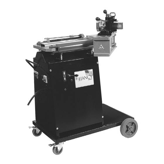
- Page 1 Jancy JB2400 Bender OPERATOR’S MANUAL WARNING! before use be sure everyone using this machine reads and understands all safety and operating instructions in this manual EYE PROTECTION NEVER PLACE LINE VOLTAGE REQUIRED FINGERS NEAR PRESENT MOVING PARTS MOdEL #JB2400 Serial #...
-
Page 2: Table Of Contents
Jancy Engineering Inc. within thirty (30) days of purchase date. This warranty is void if the item has been dam- aged by accident, neglect, improper service, or other causes not arising out of defects in materials or workmanship. -
Page 3: Important Safety Instructions
8. keep All Guards in Place Keep all guards in place and in working order. • 9. Avoid contacting Moving Parts 10. Secure The JB2400 Bender Lock the casters and chock the wheels to prevent machine from moving when in use. • 11. Before Servicing Disconnect the power supply before servicing the machine. - Page 4 important safety instructions 12. Reduce The Risk of Unintentional Starting Make sure switch is in the off position before plugging in. • 13. Never Leave Tool Running Unattended Turn power off. Don’t leave tool until it comes to a complete stop. •...
-
Page 5: Grounding Instructions
grounding instructions WARNING! Improperly connecting the grounding wire can result in the risk of electrical shock. Check with a qualified electrician if you are in doubt as to whether the outlet is properly grounded. Never remove the grounding prong from the plug. -
Page 6: Getting Started
( before you begin ) Remove all contents from packaging and inspect to ensure no damage was incurred during shipping. Your JB2400 package should also include the following: description part operator’s manual LIT115 5/8” allen Wrench JB000108 1 3/32"... -
Page 7: Turning On The Power
operating instrucions The Jancy Bender is designed to accommodate a wide variety of tube and pipe diameters and wall thicknesses. To ensure a quality bend, use the appropriate sized tooling for the material being bent. Example: 1.50” pipe is 1.90” OD, where as 1.50” tube is 1.50” OD. In most cases a Center Line Radius (CLR) of three (3) times that of the outer diameter should be used. -
Page 8: Making A Bend
maKing a bend WARNING: Before powering up the machine, ensure that all moving parts are clear of obstructions, all bolts have been secured, and that the control lever is in the center/neutral position. - Ensure that the appropriate tooling is installed for the bending material. - Turn main power on. -
Page 9: Maintenance & Troubleshooting
32, or equal (100 SUS to 350 SUS at 100 oF). Minimum of 4” from top of tank to oil is needed for proper oil circulation. DO NOT OVER FILLTANK. JB2400 voltage conversion See instruction sheet 0111DOC for complete instructions and diagrams for voltage conversion. -
Page 10: Appendix A: Bend Quality And Troubleshooting
troubleshooting Appendix A: Bend Quality and Troubleshooting Minimum Center Line Radius Guidelines Tube Tube Wall Thickness diameter 0.039 0.047 0.059 0.079 0.098 0.118 0.128 0.138 0.157 0.177 0.250 0.375 0.500 0.625 0.750 0.875 1.000 1.125 1.250 1.375 1.500 1.625 1.750 1.875 2.000 2.125... -
Page 11: Appendix B: Common Pipe And Tube Bending Terms
Appendix B: common Pipe and Tube Bending Terms O.d.: Outside diameter in inches of the Arc: The curved portion of tube or pipe tube or pipe. bends. See Pipe Bending Diagram. Out of Plane: The deviation in the centerline Radius (cLR): Distance in horizontal plane of a single pipe bend inches from the center of curvature to the between its tangent points, based on the... -
Page 12: Parts Breakdown
90 degree Pipe Bends Legend CLR= Center Line Radius a= bend angle L = Arc length (outside) R = Rise (inside) D = Tube outside diameter t = Tube wall thickness A= First tangent length B= Ending tangent length Offset Pipe Bends Legend a = First bend arc angle b = Second bend arc angle... -
Page 14: Parts List
JBL24609 BASE CABINET ASSY. JBL24605 JB2400 CENTRAL SUPPORT TUBE JBL24604 RIGHT SIDE BENDING ARM JBL24601 LEFT SIDE BENDING ARM JBL24602 FORM DIE DRIVE ASSY. JBL24603 PRESSURE DIE PIVOT CAM ASSY. JBL24003 HYDRAULIC CYLINDER AND FITTINGS... -
Page 15: Maintenance Records
maintenance record date Maintenance Performed... - Page 16 your distributor Tel · 563.391.1300 or Fax · 563.391.2323 2735 Hickory Grove Road · Davenport, Iowa 52804 email · jancy@jancy.com / web · jancy.com LIT115D ©03/07...
Need help?
Do you have a question about the JB2400 and is the answer not in the manual?
Questions and answers