Table of Contents
Advertisement
Quick Links
Reach PoE4N Tester Manual 1.4
© Copyright Reach Technology, a Novanta Company, 2005-2017
All Rights Reserved
Information contained in this user documentation is subject to change without notice and does not
represent a commitment on the part of Reach Technology. Reach Technology assumes no
responsibility or liability for any errors or inaccuracies that may appear in the user
documentation.
Reach PoE4N Tester Manual 1.4
Model RT-PoE4N
Software Version 1.0 and above
August 09, 2017
08/09/2017
Reach Technology
www.reachtech.com
Sales
408-754-4176
sales@reachtech.com
Support
503-675-6464
techsupport@reachtech.com
Page 1
Advertisement
Table of Contents

Related Manuals for Reach Technology RT-PoE4N

Summary of Contents for Reach Technology RT-PoE4N
- Page 1 Information contained in this user documentation is subject to change without notice and does not represent a commitment on the part of Reach Technology. Reach Technology assumes no responsibility or liability for any errors or inaccuracies that may appear in the user documentation.
-
Page 2: Table Of Contents
Table of Contents REVISION HISTORY ......................4 1.1. RTI-P E4N - B ....................4 ODEL GENERAL ..........................5 2.1.......................... 5 VERVIEW 2.2........................5 RONT PANEL 2.3........................... 6 EATURES 2.4........................6 IMENSIONS 2.5..................6 LECTRICAL HARACTERISTICS 2.6. - Page 3 RESET ............................19 SET ............................20 STATUS ............................ 20 TEMPERATURE ........................20 APPENDIX A - OPERATIONAL NOTES ................21 ........................21 OWER ......................22 RROR MESSAGES APPENDIX B - TEST SETUPS ....................23 ........................23 VERVIEW ......................23 IGNATURE ETECT ........................
-
Page 4: Revision History
Revision History RTI-PoE4N - Base Model 1.1. The Model RT-PoE4N is the initial version in production. It can be recognized by the version string as follows (see the VERSION command; also seen on power-on). Reach PoE Tester Model RT-PoE4N/24 PN 53-0003-11 Rev A 01 SW 1.02 07/01/2014 Copyright (C) 2005-2014 by Reach Technology Inc. -
Page 5: General
24 Powered Device (PD) loads in a 1U high chassis. Each RT-PoE4N port passes up to GbE speed traffic to the next port to facilitate data traffic testing. That is, Port 1 data connects to Port 2, 3 to 4, and so on. This is useful when the PSE has diagnostics to do port-to-port traffic testing, or when the PSE is set up for port pair VLANs to force traffic through all ports. -
Page 6: Features
1.74" high Electrical Characteristics 2.5. The RT-PoE4N is powered via a locking power DIN 4 pin connector and requires 12V DC at a maximum of 8.5 Amps. The unit is supplied with a worldwide universal AC input power supply brick. Its characteristics are: 85-264VAC input, 87.5% efficient, 0 to 40C operation, IEC320/C14 input... -
Page 7: Configuration Guide
UUT (Unit Under Test) Connections 3.3. The RT-PoE4N has twenty-four identical test ports. Connect the port of the PSE (PoE Supplying Equipment) under test to the port connector via a standard straight through Ethernet cable. The PSE data will be routed to the next port (1 to 2, 3 to 4, etc) on a straight-through, non-crossover basis. -
Page 8: Connectors And Jumpers
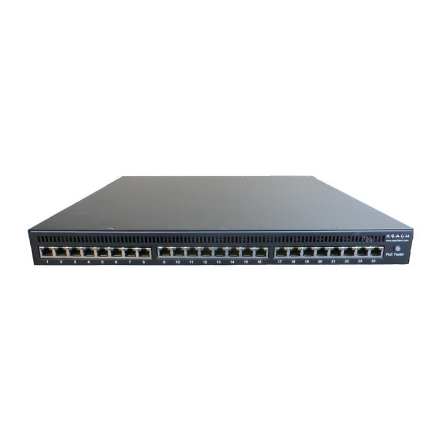
RJ-45 Ethernet Connectors 4.1. Picture 2: Far left side of RT-PoE4N front panel There are 24 numbered UUT ports. The RJ connector should be cabled to the corresponding PSE port using a standard Ethernet 1-1 jumper cable. When enabled via software command, the data component of the port N (N=1,3,5,…) will be connected to... -
Page 9: Ethernet Power Selection
Ethernet Power Selection 4.3. Unlike the RT-PoE3N model, there are no jumpers required to set which conductors provide power. The unit contains two separate power paths for pair 1,2 / 3,6 and for pair 4,5 / 7,8. These have the standard full wave bridge so any polarity is accepted. The voltage measurement function accommodates either polarity and can be used to validate the expected PSE port polarity. -
Page 10: Operational Overview
Operational Overview Data path 5.1. The data path section allows the UUT port data to be in two states: disconnected, or connected to the data of the next UUT port. This allows data to pass from port to port for testing. -
Page 11: Power Input
Power input 5.2. Power Input (above); 2 instances, one for each power pair: Each UUT port can have either power pair measured (reported voltage can be positive or negative depending on polarity), or connected to the Full Wave Bridge and subsequent load circuits. -
Page 12: Signature, Class, And Load
Signature, class, and load 5.3. 2 of these, one for each power pair Power Pair Legacy capacitive signature 10uF "cap" command Full wave Bridge and standard Signature options IEEE 802.3at overvoltage controller protection "detect" commands Class options Power Status "status" command "class"... -
Page 13: Fans
Fans 5.4. The fans engage when any of the test ports have been issued the “connect” command. After all ports are no longer connected (e.g. reset command has been issued) the fans will stay on until nominal heatsink temperature has been reached. RJ45 LEDs 5.5. -
Page 14: Command Reference
This section describes the commands available. For typical command sequences, see Appendix When the unit is ready for a command, it issues the default prompt "RT-PoE4N>". The prompt may be changed via the "hostname" command so that a unit can be identified by its prompt. -
Page 15: Error Check
ERROR CHECK Description: The unit maintains an error flag that is set if any error message is generated. This command reports the error flag value. A test script can run an entire sequence of commands and check at the end to make sure there were no errors instead of having to check on a command-by- command basis. -
Page 16: Echo
ECHO Description: Used to test the communication between the host and this unit. This is useful at higher baud rates to validate a baud can be used without error. A script can repeat the echo command continuously and verify that no communication errors are present. -
Page 17: Cap
Description Controls the 10uF capacitor across the full-wave bridge. This represents either a legacy capacitive signature or an AC load. cap [on|off] Command: printf(":p%d cap %d\r\n", port, state); Response: state = 1 or 0 for on and off respectively. CLASS Description Sets the IEEE load class. -
Page 18: Connect
CONNECT Description Controls the relays that connect the power load circuitry to the UUT port via the GbE transformer. From a power perspective, this is equivalent to plugging in the RJ45 from the UUT. See the Operational Overview section for more details. Connect must be on for the UUT to see an IEEE 802.3af/at PoE load. -
Page 19: Measure
MEASURE Description Measures the voltage from the UUT (center taps of GbE magnetics) of the main. Reports the voltage as either positive or negative depending on the polarity of the pair. The “Cisco” standard 1,2 = negative, 3,6 = positive is reported as a positive voltage. meas[ure] Command: printf(":p%d %d.%uV\n\r",port,fval);... -
Page 20: Set
Description Sets power load value in milliamps. If set too low, the minimum value will be set; if at or above 1400mA an error will occur. Note that this is the load for both the main and the alt pair. set <value>... -
Page 21: Appendix A - Operational Notes
When the unit is powered on, it performs a self-calibration of its power load. This takes around 10 seconds. While calibrating, the unit flashes the front panel LED and displays the following. The prompt "RT-PoE4N>" indicates that the unit is ready for commands. RT-PoE4N>”(revision dependent version string)”... -
Page 22: Error Messages
Error messages All error messages begin with the "!" exclamation mark. Error Message Description !Syntax error There was syntax error in the previous command. !Reach PoE Tester... There is an internal version error in this unit. ! invalid port value The value given with the port prefix was not valid. -
Page 23: Appendix B - Test Setups
Appendix B - Test Setups Overview This Appendix gives an overview of basic test setups. No port or group prefixes are shown. PSE, PD as defined in IEEE 802.3af. The RT-PoE4N commands are issued in the order shown. Signature Detect... -
Page 24: Power Status And Overload (Ieee 802.3Af)
Power Status and overload (IEEE 802.3af) RT-PoE commands: PSE action reset connect on detect ok class 3 set 20 Enable power to port Verify that PSE sees that device taking power. status (verify that power is meas2 (verify that voltages are as expected ) set 350 (Verify that PSE is providing full power) -
Page 25: Appendix C - Specifications
Appendix C - Specifications Measurement Specifications Voltage Measurement ± 2% or ±0.5V whichever is greater Current setting, power ± 2% or ±2mA whichever is greater load 5mA load guaranteed less than 5mA 10mA load guaranteed greater than 10mA Current setting, class load ±...
Need help?
Do you have a question about the RT-PoE4N and is the answer not in the manual?
Questions and answers