
Subscribe to Our Youtube Channel
Summary of Contents for ABX Pentra 80 RAB108EA
- Page 1 User Manual P/n: RAB108EA ABX Diagnostics B.P. 7290 34184 MONTPELLIER Cedex 4 - FRANCE...
- Page 2 The information in this manual is distributed on an «as is» basis, without warranty. While every precaution has been taken in the preparation of this manual, ABX Diagnostics will not assume any liability to any persons or entities with respect to loss or damage, caused or alleged to be caused directly or indirectly by the instructions contained in this manual or by the computer software and hardware products described herein.
- Page 3 Section1: Introduction 1. Warning and precautions ..........1-2 1.1. Limited guarantee ..............1-2 1.2. Safety Precautions..............1-3 1.3. graphics and symbols............. 1-4 2. Labels ................1-5 2.1. Input/Output Labels ............... 1-5 2.2. PC connections label ............. 1-7 3. Operational conditions ........... 1-8 3.1.
- Page 4 1.2. Printer start up ............... 2-2 1.3. Pentra 80 Startup ..............2-2 1.4. Status ..................2-5 2. Running the ABX Quality Control ........2-6 2.1. Closed tube Mode with barcode ..........2-6 2.2. Open tube ................2-7 3. Running specimen ............2-9 3.1.
- Page 5 Section 3: Quality Assurance & Logs 1. Quality control..............3-4 1.1. Access to the Quality Control Menu ........3-4 1.2. L.J. Graphs ................3-6 1.3. QC data screen grid ............... 3-7 1.4. Graphics screen ..............3-8 1.5. Print, send or delete results ............ 3-9 1.6.
- Page 6 Section 4: Workflow 1. Workflow ................ 4-3 1.1. Sample tube management............4-3 1.2. Workflow................4-4 1.3. Worklist ................. 4-4 1.4. Sample identification ............. 4-5 1.5. Barcode Identification............4-5 1.6. Sample identification on Rack/position ........4-8 1.7. Exception management............4-11 1.8. Sample tube and order association........4-13 1.9.
- Page 7 Section 5: Settings 1. Menu «Settings» overview..........5-3 1.1. Accessing the «Settings» menu..........5-3 1.2. Menu Settings functions ............5-4 2. Soft parameters ............... 5-5 2.1. Accessing the Soft Parameters menu ........5-5 2.2. General tab................5-6 2.3. Department/Physicians tab............. 5-8 2.4.
- Page 8 8.1. Accessing the «Types» parameters menu ......5-33 8.2. Pathological limits ............... 5-36 8.3. Alarms & Curve thresholds........... 5-37 8.4. Age range ................5-41...
- Page 9 Section 6: DescriptionTechnology 1. Pentra 80 description ............6-2 1.1. Front View ................6-2 1.2. Left side view ................. 6-2 1.3. Right side view ..............6-3 1.4. Stat tube holder..............6-3 1.5. Rear view................6-4 2. Automatic mode principles ..........6-5 3.
- Page 10 Section7: Maintenance & Troubleshooting 1. Maintenance & Troubleshooting procedures ....7-3 1.1. Hydraulic cycles maintenance chart table......7-3 1.2. Maintenance procedures............7-3 1.3. Instrument general cleaning ........... 7-4 2. .Replacement procedures..........7-5 2.1. Reagent replacement ............. 7-5 2.2. Optical bench lamp replacement......... 7-11 2.3.
- Page 11 Section 8: Specifications 1. Technical specifications ..........8-2 1.1. Parameters ................8-2 1.2. Throughput Analyses ............. 8-3 1.3. Tube identification..............8-4 1.4. Reagents ................8-4 1.5. Internal Computer ..............8-4 1.6. Measurements and computation ..........8-4 2. Physical specifications ............ 8-5 2.1.
- Page 12 Section9: Glossary 1. Glossary................9-2 2. Index................9-4 3..................9-11...
-
Page 13: Table Of Contents
Introduction Contents Section 1: 1. Warning and precautions........1-2 1.1. Limited guarantee............1-2 1.2. Safety Precautions ............1-3 1.3. graphics and symbols ..........1-4 2. Labels ..............1-5 2.1. Input/Output Labels............. 1-5 2.2. PC connections label........... 1-7 3. Operational conditions ........... 1-8 3.1. -
Page 14: Warning And Precautions
To validate the guarantee, ensure the following is adhered to: 1 - The system is operated under the instructions of this manual. 2 - Only software or hardware specified by ABX Diagnostics is installed on the instrument. This software must be the original copyrighted version. -
Page 15: Safety Precautions
1.2. Maintenance procedures, page 7-3). If this instrument has been supplied to you by anyone other than ABX Diagnostics or an authorised representative, ABX Diagnostics cannot guarantee this product in terms of specification, latest revision and latest documentation. Further informa- tion may be obtained from your authorised representative. -
Page 16: Graphics And Symbols
Pentra 1.3. graphics and symbols Switch off position Switch on position Alternating current Manufacturer This product conforms to the EEC In Vitro Diagnostic Medical Device Standards and Directives named in the Declaration of Conformity. Caution, consult accompanying Biological risk documents Reagent Fragile, handle with care Keep dry... -
Page 17: Labels
Introduction Labels 2. Labels 2.1. Input/Output Labels Fig. 1–1 Rear panel labels 2.1.1. Identification label Fig. 1–2 Serial number label 1–5 Pentra 80 - User Manual - RAB108EA... - Page 18 Fig. 1–4 Ouput Label 1- RS 232 output: LIS (Laboratory Information System) connection. 2- Printer connection: Do not connect any printer which has not been recommended by an ABX Diagnostics qualified engineer. 1–6 Pentra 80 - User Manual - RAB108EA...
-
Page 19: Pc Connections Label
Introduction Labels 2.2. PC connections label Fig. 1–5 Internal PC connections 1 - Mouse 2 - Keyboard Refer to 3.9. Interconnections, page 1-11, for other peripheral connections. 1–7 Pentra 80 - User Manual - RAB108EA... -
Page 20: Operational Conditions
INSTALLATION CATEGORY II and POLLUTION DEGREE 2 (IEC EN 61010-1). Please contact your local ABX Diagnostics representative for information regarding operation locations, when it does not comply with the recommended specifications. -
Page 21: Grounding
Introduction Operational conditions Fig. 1–6 Power ON/OFF switch 3.3. Grounding Proper grounding is required when installing the system. Check the wall outlet ground (Earth) for proper grounding to the facilities electrical ground. If you are unsure of the outlet ground- ing, contact your facilities engineer to verify the proper outlet ground! 3.4. -
Page 22: Transportation And Storage Conditions
Pentra If any doubt, please contact your ABX Diagnostics representative service depart- ment. 3.7. Transportation and storage conditions Storage temperature: -20°C +50°C. Prior to the shipping of an instrument by transporter, whatever the destination, an external decontamination of the instrument must be carried out. -
Page 23: Interconnections
Introduction Operational conditions 3.9. Interconnections 3.9.1. Electrical & Computer connections (see 2.2. PC connections label, page 1-7) Fig. 1–7 Computer connections 1. VGA 5. 2 X USB 8. COM2: Labo Link 2. Mouse 6. Printer 9. COM1: To Mother Board 3. -
Page 24: Racks
Pentra 3.10. Racks The ABX PENTRA 80 racks are identified on the system by means of Barcode labeling. These labels must be placed on the racks in the following manner: Fig. 1–8 Rack barcode Identification and Rack type (Front side) Fig. -
Page 25: Software Overview
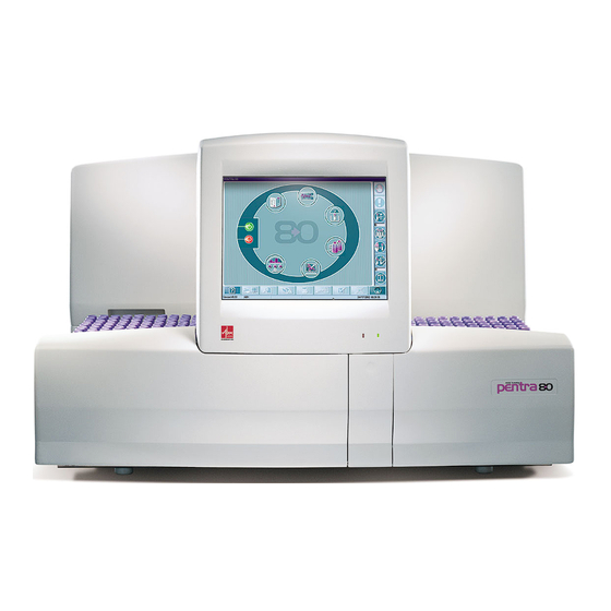
Software overview 4. Software overview PENTRA 80 includes a control station which software, designed by ABX DIAGNOSTICS, is in- stalled on a loading PC with a twelve inch 800 x 600 operated touch screen. The Main Menu of the system includes two-menu selection bars located on the lower horizon- tal and right vertical portions of the touch screen.,... -
Page 26: Generic Toolbar Description
Pentra 4.1. Generic toolbar description This toolbar that located at the bottom of the screen, contains the same selections regardless of what initial menu is open. Name Function Description Help Help Brings up the help file Details Details Details/displays supplementary information Insert Insertion Inserts new data... -
Page 27: Contextual Toolbar Description
Introduction Software overview 4.2. Contextual toolbar description The Contextual toolbar function keys are accessed from the toolbar located on the right side of the screen. These function keys are the most frequently used besides the Main Cycle Launch keys. Name Action Indicator Stop... -
Page 28: Main Menu Description
Pentra 4.3. Main Menu description Access to the main functions of the system: Name Action Indicator The gauge on the bottom status bar progresses at the same time Startup Runs the startup cycle as the cycle. Flashes when the «Startup» cycle has to be performed. -
Page 29: Miscellaneous
Introduction Software overview 4.4. Miscellaneous 4.4.1. Software arborescence and Hints ◆ keys, Tabs, Function keys can be enabled or disabled according to the instrument or soft- ware status: Enabled Disabled ◆ Menu headings are displayed at the top of the screen when a menu is selected ◆... - Page 30 Pentra Fig. 1–12 Menu tabs 4.4.3. Scrolling list These small menus include a list of options, and sometimes include a “Free Field” to enter or edit data within the menu. The «Edit» key must be selected to access a «Scrolling list». Fig.
- Page 31 Introduction Software overview Fig. 1–14 Checked box 4.4.5. Radio button Selection between options excluding each other Fig. 1–15 Radio button The «Edit» key must be selected to modify the «Radio button». 4.4.6. Data Fields These fields are rectangular areas within a specific menu that are used to display, input, or edit specific information within each field.
- Page 32 Pentra Fig. 1–16 data Fields The «Edit» key must be selected to modify a «data field». 4.4.7. Sliders When data can not be displayed within the same window, a horizontal or vertical slider will appear. Drag it or click the arrows to move through all the data. Fig.
-
Page 33: Workflow Overview
Introduction Workflow overview 5. Workflow overview Connected or not, PENTRA 80 introduces an «exchanged workflow process» based on a secure managements of orders whether connected to a Host computer or just by itself (see 5.1. Order overview, page 1-21). With either configuration, the system secures the in- formation being processed: For Worklist (see 5.2. - Page 34 Pentra Patient Sample Order Service Fig. 1–18 Order management 1–22 Pentra 80 - User Manual - RAB108EA...
-
Page 35: Worklist Overview
Introduction Workflow overview 5.2. Worklist overview ◆ A worklist is the list of orders generated on a daily basis (See Section 4, Worklist, page 4-14). ◆ Orders are removed from the Worklist after analysis. ◆ The minimum information required for an order is: –... -
Page 36: Runs And Results Overview
Pentra 5.3. Runs and results overview ◆ Analytical processes and obtained results are defined as «Runs». Individual parameter se- lection allows an easier verification of the final result ◆ Sample results are determined from runs, automatic reruns and manual runs required for an order Section 4, 6. -
Page 37: Archives Overview
Introduction Workflow overview 5.4. Archives overview Archives contain previous run & results that can be accessed by the user. Using two different modes available on the PENTRA 80 can access the archives. ◆ Review by date or ◆ Review by patient Runs &... - Page 38 Pentra Search by Patient Id Date 1 Date 2 Date 3 Date 4 Fig. 1–22 Review by Patient 1–26 Pentra 80 - User Manual - RAB108EA...
-
Page 39: Results Production
Introduction Workflow overview 5.5. Results production Results are produced in two forms of sample identification: «Matched Results» (Results matched to a specific order) Worklist Analytical process Runs & results Archives Sample Id1 Patient 1 Order 1 Sample Id2 Patient 2 Order 2 Sample Id3 Patient 3... -
Page 40: Printer
Pentra 6. Printer Use the printer supplied or approved by ABX DIAGNOSTICS 1–28 Pentra 80 - User Manual - RAB108EA... - Page 41 1.3.1. Automatic startup ........... 2-4 1.3.2. Manual startup ..........2-4 1.3.3. Background count verification......2-4 1.4. Status................2-6 2. Running the ABX Quality Control......2-7 2.1. Closed tube Mode with barcode ........2-7 2.2. Open tube ..............2-8 3. Running specimen..........2-10 3.1.
-
Page 42: Instrument Startup
Pentra Section 2: Daily Guide This section describes basic daily operations, including: 1. Instrument Startup, page 2-2 2. Running the ABX Quality Control, page 2-6 3. Running specimen, page 2-9 4. Results, page 2-13 5. Archives, page 2-15 6. Instrument Shutdown, page 2-16 1. -
Page 43: Automatic Startup
Daily Guide Instrument Startup The «Begin of day» screen includes the following options: ◆ Erase worklist: when checked, deletes all the or- ders recorded in the worklist menu (checked by default). ◆ Reset Autonumbering: when checked, starts the autonumbering to AUTO_SID1 (See Section 5, 2.2.2. - Page 44 Pentra The background count results are printed out. Verify that the Background count is within its limits values as indicated: Instrument default values: WBC< 0.3 10 RBC< 0.03 10 HGB< 0.3 g/dl PLT< 7 10 LMNE< 0.30 # Nota: These options are available in the «Begin of day» screen when: - the instrument is started on a new working day (date changed) - the Begin of day time (See A on Fig.
-
Page 45: Status
Daily Guide Instrument Startup 1.4. Status Press the «Status» key of the Main Menu screen. This screen indicates the current levels of reagents. If reagents levels are low and need repla- cement refer to Section 7, 2.1. Reagent replacement, page 7-5 2–5 Pentra 80 - User Manual - RAB108EA... -
Page 46: Running The Abx Quality Control
(temperature, mixing, etc...). «ABX DIFFTROL» This control material is specifically designed for use on the ABX PENTRA 80, which includes a com- plete Blood Count and 5-part White blood cell differential. (CBC & DIFF) Features include (Barco- des, batch numbering, logs, etc…). -
Page 47: Open Tube
Daily Guide Running the ABX Quality Control If any parameter results and/or any statistical Data are displayed in “RED”, perform the following steps: 1- Verify that the analyzed QC results correlates with control lot, (scrolling list). If they do not... - Page 48 Place the control vial in the appropriate position of the tube holder and close the TUBE HOLDER DOOR. (The Cap of the ABX DIFFTROL allows for cap piercing). If you do not want to pierce the cap, re- move it and proceed by placing the sample and closing the tube holder door.
-
Page 49: Running Specimen
Daily Guide Running specimen 3. Running specimen 3.1. Sample identification with internal barcode reader, page 2-9 3.2. Non-identified sample with external barcode reader, page 2-9 3.3. Stat mode, page 2-11 3.4. Run in progress, page 2-12 3.1. Sample identification with internal barcode reader Position the sample tubes into the cassettes as indi- cated in the picture (barcode label facing out and to the front) - Page 50 Pentra Choice of data entries areas followed: 1- Sample information 2- Patient information 3- Test selection: CBC (yellow), DIF (green). Press the «OK» key to confirm the order of each sam- ple tube. Place the tube in the rack, then repeat the data entry for the next position.
-
Page 51: Stat Mode
Daily Guide Running specimen 3.3. Stat mode Stat mode may be selected at any time during the sys- tem processing of the rack: Press the «STAT MODE» key. The «Stat order screen» will be displayed as Enter the identification information of the sample that you run as a STAT: ◆... -
Page 52: Run In Progress
Pentra When the STAT order information has been entered, se- lect the “OK” key to confirm your entry. Both LED’s on the front panel will flash indicating that the routine rack analysis is going to be interrupted. When the instrument is ready, the tube holder door opens (the «START RACK»... -
Page 53: Results
Daily Guide Results 4. Results 4.1. Printing a result series, page 2-13 4.2. Unmatched results, page 2-14 Results of the day can be reviewed by selecting the «RESULTS» key on the generic toolbar (located on the right vertical portion of the touch screen). 4.1. -
Page 54: Unmatched Results
Pentra 4.2. Unmatched results Unmatched results are sample results that are not mat- ched to a Worklist order. These results can be reviewed by selecting the «ASSOCIATION» key 2–14 Pentra 80 - User Manual - RAB108EA... -
Page 55: Archives
Daily Guide Archives 5. Archives 5.1. Searching results by day, page 2-15 5.2. Searching results by patient, page 2-15 Press the «ARCHIVES» key on the Generic toolbar. 5.1. Searching results by day Open the calendar of the «Daily results» view, select «Running Date», and then select the date of the results you wish to review. -
Page 56: Instrument Shutdown
5-25) or manually activated by selection. 6.1. Manual shutdown From the Main Menu screen, press the «SHUTDOWN» key to perform a complete instrument enzymatic cleaning with ABX CLEANER. When the Shutdown cycle is complete, select «Stop win- dows» to turn off the instrument. 2–16... - Page 57 Quality Assurance Contents 1. Quality control ............3-4 1.1. Access to the Quality Control Menu ......3-4 1.2. L.J. Graphs..............3-6 1.3. QC data screen grid............. 3-7 1.4. Graphics screen............3-8 1.5. Print, send or delete results.......... 3-9 1.5.1. Printing results..........3-9 1.5.2.
- Page 58 Pentra 5.7. Error logs ..............3-35 5.8. Host logs..............3-35 5.9. Blank cycle logs............3-35 5.10. Patient logs ..............3-36 3–2 Pentra 80 - User Manual - RAB108EA...
-
Page 59: Quality Control
Quality Assurance Section 3: Quality Assurance & Logs The «Quality Assurance» menu is accessible by selecting the Quality Assurance key from the Main Menu screen. Fig. 3–1 Quality Assurance access key Four functions are available in this menu: ◆ Quality Control (see 1. -
Page 60: Access To The Quality Control Menu
Pentra 1. Quality control ◆ The Quality Control allows the monitoring of a set of analyses based on known samples over a period of several months. Statistical computations performed on these populations allow the extraction of qualitative information related to the stability of the instrument. ◆... - Page 61 Quality Assurance Quality control ▼ Quality Control Key Name Function Switches from LJ Graph to Data Grid window Details (see 1.3. QC data screen grid, page 3-7) Access to the Target values window Target (see 1.6. New blood control setup, page 3-10) Displays the last QC run in a full screen mode Matrix...
-
Page 62: Graphs
Pentra 1.2. L.J. Graphs This is the graphical representation of Quality control data based on the daily value for each Control parameter, its target value, and range that are plotted on a graph for periodic review. A total of 100 points per parameter can be displayed on the screen and on the printout. The hematology parameters are displayed in groups of 5. -
Page 63: Qc Data Screen Grid
Quality Assurance Quality control 1.3. QC data screen grid From the L.J. graphs screen, use the «Details» key to display the «QC data screen grid». ▼ Analyses results 1- Check boxes: select/ deselect QC data. 2- Operator that processed the control runs 3- Date and time that the QC run was processed 4- Filter: (DIFF, CBC or All... -
Page 64: Graphics Screen
Pentra ◆ One or more results may be excluded from the CV calculations by using the check boxes for selection or deselection of QC results. Statistical calaculations are re- computed after each selection/deselection of results. ◆ There is not limit on the number of results to be saved for a specific blood con- trol lot. -
Page 65: Print, Send Or Delete Results
Quality Assurance Quality control 1.5. Print, send or delete results 1.5.1. Printing results ▼ Graphics screen Results are printable from the «Graphics screen» (see Fig. 3–5, page 3-8) in a full screen mode. . Select the «Print/Send» key. Then select the «OK» key. ▼... -
Page 66: Deleting Results
▼ Target initialization by floppy Each order of Blood controls (ABX DIFFTROL) comes with a floppy disk so that the operator can insert the disk and update the new control lots without any manual entry of data. Lot #, Target values and Ranges, Alarms and Thresholds, and Expiration Date are included on the floppy disk for each level of control. - Page 67 Quality Assurance Quality control Now select the «Edit» key. When modifying a control lot, analyses from the previous lot must be erased. A Warn- ing message will be displayed. Select the «OK» key to delete all previous control lot information. ◆...
- Page 68 Pentra ◆ Use the scrolling box key to open a calendar and select the expiration date. ◆ Modify or enter target values by selecting the area in which you want to replace the value. Fig. 3–11 Control expiration date Fig. 3–12 Manual entry of target value By selecting the tab «Threshold», you can also modify threshold and Alarm levels.
-
Page 69: Running Control Blood
Quality Assurance Quality control 1.7. Running control blood 1.7.1. Running in STAT mode Verify that the lot of control blood has been entered as described in 1.6. New blood control setup, page 3-10. Prepare the Blood control according to the specific instructions detailed in the blood control package insert (temperature, mixing...). -
Page 70: Patient Quality Control (Xb)
Pentra 2. Patient Quality Control (XB) The (XB) Patient Quality Control is used to detect any change in the quality of results by use of patient data only. This data monitoring is performed without any user intervention and can be applied to a set of 9 parameters (WBC, RBC, HGB, HCT, RDW, PLT, MCV, MCH, MCHC) or 3 parameters (MCV, MCH, and MCHC). -
Page 71: Access To The Xb Menu
Quality Assurance Patient Quality Control (XB) 2.1. Access to the XB menu From the «Quality Assurance Menu» (see Fig. 3–1, page 3-3), select the «XB» key. Fig. 3–13 XB Graphic screen ▼ XB Keys Name Function Switches from LJ Graph to Data Grid screen Details (see 2.3. -
Page 72: Xb Graphs
Pentra 2.2. XB Graphs The XB Graphs (see Fig. 3–14, page 3-16) are a representation of each batch parameter and their limits plotted on a graph, up to 60 batches. All 60 batches will be displayed on the screen and on the printout (see 2.5. -
Page 73: Xb Data Grid Screen
Quality Assurance Patient Quality Control (XB) 2.3. XB Data Grid screen From the «XB graphs» menu (see Fig. 3–14, page 3-16), select the «Details» key to open the «XB Data Grid» screen (see Fig. 3–15, page 3-17) Fig. 3–15 XB Data grid screen The XB data grid contains the individual hematology data as well as the batch number. -
Page 74: Batch Content
Pentra 2.4. Batch content When selecting the XB Batch content, this will display all 20 results within that specific batch. From the «XB Data Grid» screen (see Fig. 3–15, page 3-17) or from the «XB Graphs» (see Fig. 3–14, page 3-16), select the «XB» key to open specifically selected batch contents. Fig. -
Page 75: Xb Limits
Quality Assurance Patient Quality Control (XB) 2.5. XB limits From the «XB Data Grid» screen (see Fig. 3–15, page 3-17) or from the «XB Graphs» (see Fig. 3–14, page 3-16), select the «Target» key to open the «XB Limits» screen (see Fig. -
Page 76: Within Run
Pentra 3. Within run The Within Run is based on results that are obtained by consecutive analyses of the same blood sample. Sections detailed in Within Run: ▼ ◆ 3.1. Accessing the Within Run Data Grid, page 3-20 ◆ 3.2. Closed tube sample setting, page 3-22 ◆... - Page 77 Quality Assurance Within run ▼ Within Run Keys Name Function Deletes Unselected/Selected or All results (see 3.3.4. Print/ Delete Transmit or delete Results, page 3-23) Prints: selected or all results or Statistics only Print/Transmit Sends: selected or all results (see 3.3.4.
-
Page 78: Closed Tube Sample Setting
Pentra 3.2. Closed tube sample setting The operator is allowed to run within run samples in both Manual Mode and Rack Mode. Enter the number of sample takes to be per- formed on the sample tube for Rack mode. Fig. 3–19 Closed tube mode setting ◆... -
Page 79: Results
Quality Assurance Within run The rack is loaded and the results will automatically appear in the grid. 3.3.3. Results Fig. 3–20 Within run results This grid includes statistical data for each parameter (maximum, minimum, mean, standard deviation). The coefficient of variation will be displayed in red, if it is greater than the upper limit established by the operator Section 5, 3.4. - Page 80 Pentra Fig. 3–21 Print/Send Within run results ▼ Delete results Open the «Within Run Data Grid» screen Using the «Delete» key (see Tab. 3–3: Within Run keys, page 3-21), discard the unselected, selected or all results from the grid: Fig. 3–22 Delete Within Run Results 3–24 Pentra 80 - User Manual - RAB108EA...
-
Page 81: Calibration
Quality Assurance Calibration 4. Calibration The Calibration function is used to determine the Precision and Accuracy of the analyzer with use of a specifically formulated product to recover each parameter within close tolerances of known target values and limits. Coefficients of variation and percent difference recovery must be within their specified limits. -
Page 82: Target Values
Pentra ▼ Calibration Key Name Function Runs an automatic calculation of the new coefficients (see 4.3.1. Calibration Automatic Calculation passed, page 3-28). This key is enabled only if a minimum of 5 runs on calibrator has been performed Access to the Target values window Target (see 4.2. -
Page 83: Running Calibration
Quality Assurance Calibration Exit the «Target values» menu by selecting the «Return» key. 4.3. Running calibration If Quality control check procedure has failed (see 1.7. Running control blood, page 3-13), 1- Verify that the reagents are sufficient, fresh, and uncontaminated. 2- Run a system “Startup”... -
Page 84: Calibration Passed
Pentra Fig. 3–25 Calibration result grid ◆ When calibration results are received on the display, they are saved as calibration data and not received as sample results. ◆ Calibration results are not transmitted to a host computer, they are kept in the calibration “Results Grid”. -
Page 85: Forced» Calibration
You have the option of continuing or rejecting the calibration at this time. 4.3.3. Coefficients of calibration ranges Check that the coefficients of calibration are within the following acceptable limits. Or else, please contact your ABX DIAGNOSTICS representative department. Coefficients of Minimum... -
Page 86: Printing, Sending Or Deleting Calibration Results3-30
Pentra 4.3.4. Printing, sending or deleting calibration results ▼ Printing and sending calibration results Calibration results can be printed out and/or sent to a host computer by selecting the «Print/ Send» key. Specific results and parameters may be included or excluded from statistical cal- culations by selection of the Check Boxes in the «Calibration Results Grid»(see Fig. - Page 87 Quality Assurance Calibration Fig. 3–29 Delete options 3–31 Pentra 80 - User Manual - RAB108EA...
-
Page 88: Logs
Pentra 5. Logs These are the event logs for the PENTRA 80. They contain all of the notifications made auto- matically by the software while the PENTRA 80 is in operation «Logs» functions are described in: ◆ 5.1. Access to «Logs» function, page 3-32 ◆... - Page 89 Quality Assurance Logs ▼ Logs access keys Name Function Launches calibration log screen (see 5.2. Calibration logs, Calibration page 3-34) Launches Quality control log screen (see 5.3. Quality control Quality Control logs, page 3-34) Launches Reagent log screen (see 5.4. Reagent logs, page 3- Reagent Launches settings log screen (see...
-
Page 90: Calibration Logs
Pentra ▼ Logs function key Name Function Opens a comment window. The user can enter a com- Add comments ment to associate to the «Logs» entry on which he is positioned permits to the user to print the current logs as a list, Print/send between two dates Tab. -
Page 91: Reagent Logs
Quality Assurance Logs ◆ Every time that an analysis made on a QC is rejected, a notification is done. 5.4. Reagent logs ◆ For every reagent change, a notification is done. 5.5. Settings logs ◆ At every modification in the settings, a notification is done. 5.6. -
Page 92: Patient Logs
Pentra 5.10. Patient logs ◆ For every modification to a patient file (by the WorkList or by the HOST), a notification is done. ◆ When exception is generated because of the mismatch of the rack/position of the sample and the order Section 4, 1.7. - Page 93 Workflow Contents 1. Workflow ............... 4-3 1.1. Sample tube management ........... 4-3 1.2. Workflow ..............4-4 1.3. Worklist............... 4-4 1.4. Sample identification........... 4-5 1.5. Barcode Identification ..........4-5 1.5.1. Setting: Barcode / Manual match = OFF ..4-6 1.5.2. Setting: Barcode / Manual match = ON ..4-7 1.6.
- Page 94 Pentra 5.3. Flags ................4-29 5.3.1. Normal and panic ranges......4-30 5.3.2. Results exceeding Linear ranges of the instrument4-30 5.3.3. Analysis reject ..........4-31 5.3.4. LMNE matrix flags ........4-32 5.3.5. Flags on WBC/BAS histogram .......4-38 5.3.6. Flags on RBC histogram ........4-39 5.3.7. Flags on PLT histograms........4-39 5.3.8.
-
Page 95: Workflow
Workflow Workflow Section 4: Workflow Worflow chapter includes the following 1. Workflow, page 4-3 2. Worklist, page 4-14 3. Sample collection & mixing, page 4-24 4. Running specimens, page 4-25 5. Run results and associated Flags, page 4-26 6. Order & sample run association, page 4-47 7. -
Page 96: Worklist
Pentra 1.2. Workflow Once the ABX PENTRA 80 has started the analysis process on a sample tube, an order is gen- erated to search the worklist for 2 of the following criteria: ◆ The Rack position number where the tube has been placed: ◆... -
Page 97: Sample Identification
Automatic numbering by the instrument. 1.5. Barcode Identification The Barcode Identification mode is the most recommended mode on the ABX PENTRA 80 be- cause it ensures the best security and flexibility. Easy association between Sample orders and the sample tube can be identified by the barcode. -
Page 98: Setting: Barcode / Manual Match = Off
Pentra 1.5.1. Setting: Barcode / Manual match = OFF The «Sample ID» field corresponds to the barcode of the label. In this mode it is impossible to allocate a position for the tube in the worklist. The P80 tab: «Settings/Soft parameters/General tab/barcode option»... -
Page 99: Setting: Barcode / Manual Match = On
Workflow Workflow 1.5.2. Setting: Barcode / Manual match = ON The P80 tab: «Settings/Soft parameters/General tab/barcode option» is set as shown: Section 5, 2.2.5. Identification option, page 5-7 Barcode Id: 123 Barcode reading Problem on reading Worklist check Worklist check Worklist unmatched Matching screen Worklist matched... -
Page 100: Sample Identification On Rack/Position
Pentra 1.6. Sample identification on Rack/position Setting: «Rack / Position» Section 5, 2.2.5. Identification option, page 5-7, i.e. that the identifier is given by the sample position on the rack. When a Barcode label is not used on a sample tube, the order must contain the sample tube position in the rack. -
Page 101: Setting: Rack/Position / Manual Match = On
Workflow Workflow Worklist sample identification P80 analysis process Sample detected on position 3 No order Result identification: Auto Numbering: Rack:x Position:y «Auto_SIDxx» Fig. 4–4 Rack position / Manual match OFF 1.6.2. Setting: Rack/position / Manual match = ON The P80 tab: «Settings/Soft parameters/General tab/barcode option»... - Page 102 Pentra Worklist sample identification P80 analysis process Sample detected on position 3 Auto Numbering:«Auto_SIDxx» Order and sample matched Matching screen Result identification: Matched with an order Rack:x Position:y Fig. 4–5 Rack position / Manual match ON 4–10 Pentra 80 - User Manual - RAB108EA...
-
Page 103: Exception Management
Workflow Workflow 1.7. Exception management The usual sample identification management is the automatic and secure matching of orders with the corresponding sample tubes. Exceptions will occur when automatic matching is impossible. For instances, when a sample tube is found in a non-defined position in the worklist, or when a barcode label cannot be read Rerun auto Sample process... -
Page 104: Sample Identification On Both Barcode And Rack/Position
Pentra 1.7.1. Sample identification on both barcode and Rack/Position If a sample tube is identified by a barcode, although the setting is «Rack / Position» Section 2.2.5. Identification option, page 5-7, the instrument checks that the worklist Sample ID corresponds to the tube barcode identification, and that the rack/position of the tube cor- responds to the one entered in the Worklist. -
Page 105: Sample Tube And Order Association
4-53. Matching non identified results with order, never modifies orders. 1.9. Patient file management The ABX PENTRA 80 Patient file management enables the filling of orders if the patient de- mographic data is known. ◆ If no data is placed into the «Patient ID» field, an automatic identification number is created as followed: «AUTO_PID_xxx». -
Page 106: Worklist
Pentra 2. Worklist 2.1. Overview A worklist is a list of orders generated on a daily basis. These orders can include: ◆ orders for samples that have not been analyzed ◆ Orders for samples that have been analyzed, but a «Rerun» status has been requested. Re- runs can be automatic according to the settings in «System Rules»... -
Page 107: Worklist Grid
Workflow Worklist ▼ Worklist view selection keys Heading / Key Name Function Displays the worklist grid view Grid view key (see 2.3. Worklist grid, page 4-15) Displays the Rack view (see 2.4. Rack view, page 4-20). Rack view key Enabled if the barcode option is on Rack/Position (see 1.3. -
Page 108: Creating An Order
Pentra 2.3.1. Creating an order From the «Worklist grid», select the «Insert» key (see Tab. 4–2: Function Keys, page 4-16) to create a new order. Fill in the order information using the right part of grid screen (see Tab. 4–3: Order fields, page 4-17). -
Page 109: Order Information Fields
Workflow Worklist 2.3.4. Order information fields Heading / Button Function Format Rack Number of rack in which the tube is placed 2 characters Pos. Tube position in the rack. Button displayed, if the Rack position has been from 1 to 10 received from the host Sample ID Entry of Sample ID... -
Page 110: Searching By Sample Id
Pentra 2.3.5. Searching by sample ID The operator has the ability to select a specific sample record from the Sample ID field. Just select the «Search Sample» key. (see Tab. 4–3: Order fields, page 4-17). The «Search Sample» key is accessible if the «Edit» or «Insert» mode has been selected. Once the «Search Sample»... -
Page 111: Printing Out The Worklist
Workflow Worklist 2.3.7. Printing out the worklist Selecting the «Print/Send» key from the Contextual toolbar will print out the «Worklist Grid». The following window appears (see Fig. 4–12, page 4-19): Fig. 4–12 Worklist printout window A «Full printing» and «Light printing» mode are available: ▼... -
Page 112: Rack View
Pentra 2.4. Rack view When no barcode are used, the order must contain the sample tube position in the rack (see 1.6. Sample identification on Rack/position, page 4-8). From the «Worklist grid» select the «Rack view» key Fig. 4–15 Capture of the rack number Read the «Rack Number»... - Page 113 Workflow Worklist Select the test type to be performed on the sample. Note the color of the indicators: ◆ DIFF in Green ◆ CBC in Yellow If a test type is not selected, an instrument Default test is performed (DIFF). The cursor automatically moves to the next rack position.
-
Page 114: Auto-Numbering
Pentra 2.4.1. Auto-Numbering If a «Sample ID» is not entered into a sample tube position, an Auto-number is given to the order as indicated: Fig. 4–17 Rack auto_numbering Select the «Worklist Grid view» key (see Tab. 4–1: Worklist selection keys, page 4-15) to display orders associated with the captured rack. -
Page 115: Printing The Rack View
Workflow Worklist 2.4.4. Printing the rack view From the «rack view» screen, Select the «Print/send» key. Fig. 4–18 Rack view print out The rack view printout ticket shows: – the patient informations – the sample informations – the clinical informations 4–23 Pentra 80 - User Manual - RAB108EA... -
Page 116: Sample Collection & Mixing
Pentra 3. Sample collection & mixing All blood samples should be collected using proper technique! Consider all Specimens, Reagents, Calibrators, Controls, etc… that contain human blood or serum as potentially infectious! Use established, good laboratory working practices when handling specimens. Wear protective gear, Gloves, Lab coats, Safety glasses and/or Face shields, and follow other bio-safety practices as specified in OSHA Blood borne Pathogens Rule (29 CFR part 1910. -
Page 117: Running Specimens
Workflow Running specimens 4. Running specimens (See Section 2, 3. Running specimen, page 2-9) 4–25 Pentra 80 - User Manual - RAB108EA... -
Page 118: Run Results And Associated Flags
Pentra 5. Run results and associated Flags «Runs results and associated flags» chapter includes: ◆ 5.1. Printer output format, page 4-26 ◆ 5.2. Result screen, page 4-27 ◆ 5.3. Flags, page 4-29 run results are displayed and printed out. A result function allows the operator to review the run results of the day 5.1. -
Page 119: Result Screen
Workflow Run results and associated Flags 5.2. Result screen Order Flags Fig. 4–19 Results display screen Results of current analysis are automatically displayed as shown. Flags appear on a «tree view» mode based on five categories: – Morphology Flags – Analyzer Alarms –... - Page 120 Pentra ▼ Zoom in feature A zoom feature is available for each parameter graphic (RBC, PLT, BAS, LMNE), by selecting the histogram or matrix representation (see Fig. 4–20, page 4-28) Fig. 4–20 Result display zoom Select the «Return» key to return the display to normal. 4–28 Pentra 80 - User Manual - RAB108EA...
-
Page 121: Normal And Panic Ranges
Workflow Run results and associated Flags 5.3. Flags Flags are divided up into 5 different groups: ◆ Flags linked to results that exceed the normal parameter limits: – 5.3.1. Normal and panic ranges, page 4-30 ◆ Flags linked to results that exceed the linear range of the instrument that leads to «Re- jected Analysis»: –... -
Page 122: Results Exceeding Linear Ranges Of The Instrument4-30
*) >1900x10 PLT value + D >5000x10 PLT replaced by «--- D» Tab. 4–5: Results exceeding linear ranges * The instrument must have been configured by an ABX DIAGNOSTICS approved technician 4–30 Pentra 80 - User Manual - RAB108EA... -
Page 123: Analysis Reject
Workflow Run results and associated Flags 5.3.3. Analysis reject A reject flag (shown by *) occurs when two counts on a parameter differ more than the pre- defined limits. It indicates that the parameter result is inconclusive and should be investi- gated for (Manual) rerun status and/or instrument malfunction if consistent on every sample. -
Page 124: Lmne Matrix Flags
Pentra 5.3.4. LMNE matrix flags ▼ Suspiscion ◆ When WBC populations are detected in abnormal quantities in one or more areas of the LMNE matrix, a «!» suspect flag will be displayed next to the parameter(s) in question. If one result appears with one or several parameters that display a «!»suspect flag, the result should be further investigated. - Page 125 Workflow Run results and associated Flags ▼ LL flag Meaning: Left Lymphocytes Absorbance Channel 127 Presence of a significantly large population on the left-hand side of the lymphocyte area. This flag appears when the number of particles counted is higher than the limit Noise set up in LL# or when the number of coun- Left...
- Page 126 Pentra ▼ NL flag Meaning: Neutro/Lympho Absorbance Channel 127 Presence of a significantly large population of cells located in the separation threshold area between lymphocytes and neutro- phils. This flag occurs when the number of Noise particles counted in this area is higher Left Right Neutro...
- Page 127 Workflow Run results and associated Flags ▼ LN flag Absorbance Channel 127 Meaning: Left Neutro Presence of a significantly large population of cells located on the left-hand side of the neutrophil area. This flag occurs when the number of particles counted in this area is Noise Left Right...
- Page 128 Pentra ▼ RM flag Meaning: Right Mono Absorbance Channel 127 Presence of a significantly large population of cells located on the right-hand side of the monocyte area (low LIC). This flag oc- curs when the number of particles counted Noise in this area is higher than the limit setup Left Right...
- Page 129 Workflow Run results and associated Flags ▼ LIC flag Meaning: Large Immature Cells Absorbance Presence of a significantly large population of cells located on RN + RM + channel 127 areas. This flag occurs when the number of particles counted in this area is higher than the limit set up in LIC#, or when the Noise number of counted particles regarding the...
-
Page 130: Flags On Wbc/Bas Histogram
Pentra 5.3.5. Flags on WBC/BAS histogram ▼ L1 flag (CBC and DIFF mode) L1 flag is established according to the ratio of the cells counted be- tween the 0 channel and BA1. L1 indicates the presence of an ab- normal number cells comparison with leukocytes. -
Page 131: Flags On Rbc Histogram
Workflow Run results and associated Flags 5.3.6. Flags on RBC histogram MIC and MAC flags are generated when the percentage of cells count- ed in the microcytic area (MIC) and macrocytic area (MAC) compared to %MIC %MAC the total number of RBCs are above the set limits for both MIC and MAC percentages set up by the user. - Page 132 Pentra An excessive presence of particles on the right side of the threshold area (after 25 fL) will generate the MIC (Microcytes) flag (shown in the plate- let alarm area). In this case the mobile threshold looks for a valley between 18fL and 25fL (standard area).
-
Page 133: Wbc Balance
◆ The WBC Balance option is not activated. (The WBC Balance can be enabled or dis- abled by an approved ABX Service Technician). Contact your local ABX Technical Ser- vice Representative for selection of this option. These flags are associated with an (!) on all differential parameters (% and#). -
Page 134: Analyzer Alarms
Pentra 5.3.9. Analyzer alarms ▼ CO flag Meaning: poor correlation. Correlation is noted as the percentage of validated cells measured between the Resistive mea- surement and the Optical measurement as they pass through the LMNE flowcell. If the cell measurements between the resistive and optical are less than 50%, a CO flag will be indicated. -
Page 135: Pathology Messages
Workflow Run results and associated Flags 5.3.10. Pathology messages Pathological suspicion messages will be displayed and/or printed out. The triggering condi- tions are linked to the laboratory limits that were entered by the user. These messages will indicate a possible pathological condition and should be used to assist with quick and efficient screening of abnormal samples along with detec- tion of certain conditions that lead to specific diagnosis. - Page 136 Pentra ▼ RBC messages Message Condition Anemia HGB < HGB L Anisocytosis RDW > RDW H Microcyte Microcyte + % MIC > 10% Microcyte ++ % MIC > 15 % Macrocyte on Mac Flag Hypochromia MCHC < MCHC L Cold Agglutinin MCHC >...
- Page 137 Workflow Run results and associated Flags ▼ PLT messages Message Condition Thrombocytosis PLT > PLT H Thrombocytopenia PLT < PLT L Microcytosis Schizocytes No threshold between RBC and PLT on the curves. Small Cell Small cells at the beginning of the Platelet curve. condition 1 PLT <...
-
Page 138: Statistical Function Flags
Pentra 5.3.11. Statistical function flags ▼ XB flag This alarm is a specific alarm that is associated with patient quality control. This particular flag is noted when batch results are outside the XB limits established by the user ◆ If one of the mean values from 1 batch of 20 samples is outside of the established limits, an XB alarm will be activated Section 3, 2.5. -
Page 139: Order & Sample Run Association
Workflow Order & sample run association 6. Order & sample run association 6.1. Reviewing sample results The Result function allows the operator to review all run results of the day, to associate un- matched results with Worklist orders, also to request Reruns. 6.1.1. -
Page 140: Result Grid Information
Pentra 6.1.3. Result Grid information Use the slider (see Fig. 4–36, page 4-47) to display all the items in the Result list as indi- cated below: - Sample ID Number, - Rack# and position of the sample tube in the rack, - Patient information: Patient ID, First name, Gender, Date of birth - Test performed - Analysis date... -
Page 141: Sorting Out
Workflow Order & sample run association 6.1.4. Sorting out Sorting samples is available in the following columns: – Date time – Sample ID – Patient ID Fig. 4–37 Result grid informations Click a column title for sorting the sample data (see Fig. -
Page 142: Result Display
Pentra 6.1.6. Result display From the result grid view, click a result line to display the results in a full screen mode as indicated below: Fig. 4–39 Result display 6.1.7. Result display keys Heading / Key Name Function Left arrow Displays the previous result in a full screen mode Right arrow Displays the next result in a full screen mode... -
Page 143: Rerunning Sample Manually
Workflow Order & sample run association 6.1.8. Rerunning sample manually The user has the ability to manually select a «Rerun» from the sample being reviewed in the «Full Screen Mode». From the result displayed in full screen mode (see Fig. 4–39, page 4-50), select the «Rerun»... - Page 144 Pentra Fig. 4–42 Selected rows printout Sending options ▼ - Send last result to the host - Send selected results to the host - Send all results to the host Fig. 4–43 Sending options screen 4–52 Pentra 80 - User Manual - RAB108EA...
-
Page 145: Result /Order Association
Workflow Order & sample run association 6.2. Result /order association 6.2.1. Association grid description From the «Result grid», select the «Association» key (This function will be disabled if all the results are already matched with orders!) Fig. 4–44 Association grid This screen will show 2 lists: ◆... -
Page 146: Association Grid Keys
Pentra 6.2.2. Association grid keys Heading / Key Name Function Deletes selected order of the Worklist: a confirmation Delete message is displayed «Do you want to delete the order which sample ID is XXX» Associates the selected order with the selected results (see 6.2.3. -
Page 147: Results Archives
Workflow Results Archives 7. Results Archives At the end of the day on the 24:00 clock, all results from the previous day are automatically archived into the system memory (if Begin of day screen has been configured as described in Section 2, 1. -
Page 148: Daily Result Description
Pentra 7.2. Daily result Description Fig. 4–47 Daily result grid The daily result grid contains all the matched results from a single day of work which include the Sample ID, the Rack number and position of the tube, the Patient ID, first name, the Test CBC/DIFF and the sample type given to the sample. - Page 149 Workflow Results Archives ▼ Daily results function keys Heading / Key Name Function Displays the search by patient screen Patient Result (see 7.3. Patient Result, page 4-58) Displays the search by date screen Daily result (see 7.2. Daily result Description, page 4-56) Opens a calendar in order to select the run date.
-
Page 150: Patient Result
Pentra 7.3. Patient Result The Archives function allows the user to review demographics of the patient. If the «Patient ID» is known, follow the steps as indicated: From the Daily results grid, select the «Patient Result» key (see Tab. 4–14: Patient result function Keys, page 4-59) Fig. -
Page 151: Patient Result Function Keys
Workflow Results Archives 7.3.1. Patient result function keys Heading / Key Name Function Displays the search by date screen Daily result (see 7.2. Daily result Description, page 4-56) When a patient is selected, Results are displayed on the right Patient ID hand side Search patient Launches the search patient Screen (see... -
Page 152: Reviewing A Result In Full Screen Mode
Pentra Now select the “OK” key to display the patient results. 7.4. Reviewing a result in full screen mode 7.4.1. Patient result screen From the «Patient Result» screen (see Fig. 4–49, page 4-58), select the result that you want to display in full screen (see Fig. - Page 153 5.2.2. Languages options........5-17 5.2.3. Change date and time ........5-17 5.3. Communication............5-18 5.3.1. RS232 settings tab: ........5-19 5.3.2. ABX/ASTM format tab ........5-19 5.4. Printer ............... 5-20 5.4.1. Printout example .......... 5-22 5.4.2. Printer properties.......... 5-23 5.5. Cycle option.............. 5-24 6.
- Page 154 Pentra 6.2.2. Workstation setting functions......5-26 6.3. Dump database............5-26 6.4. Update of the Help on line of P80 software ....5-27 7. User profiles............5-29 7.1. Accessing the User screen..........5-29 7.2. User menu function keys ...........5-30 7.3. Creating a new «User» profile ........5-30 8.
-
Page 155: Menu «Settings» Overview
Settings Menu «Settings» overview Section 5: Settings The following section is the PENTRA 80 «Settings» menu description, including 1. Menu «Settings» overview, page 5-3 2. Soft parameters, page 5-5 3. Quality assurance settings, page 5-11 4. Rules, page 5-13 5. System, page 5-17 6. -
Page 156: Menu Settings Functions
Pentra 1.2. Menu Settings functions Name Function Soft Opens the management screens for software options Parameters (see 2.1. Accessing the Soft Parameters menu, page 5-5) Allows to define CV for calibration, QC and Within Run Quality (see 3. Quality assurance settings, page 5-11). -
Page 157: Soft Parameters
Settings Soft parameters 2. Soft parameters 2.1. Accessing the Soft Parameters menu From the «Settings» window, select the «soft parameters» key. This will bring up the Soft pa- rameters general menu Fig. 5–2 Soft parameters - General menu There are three tabs available from this menu: ◆... -
Page 158: General Tab
Pentra 2.2. General tab 2.2.1. General tab functionalities Key/Heading Name Function Defines the initial value of the autonumbered Sample Auto Numbering Auto Numbering ID (see 2.2.2. Automatic numbering, page 5-6) Enables/disables RUO parameters for printing and RUO parameters RUO parameters sending operations (see 2.2.3. -
Page 159: Instrument Logs
Settings Soft parameters 2.2.4. Instrument Logs When a reagent is replaced, an instrument calibration is performed, and/or a maintenance operation is carried out, a report of these interventions is automatically created in the ap- propriate instrument log (Reagents, Calibration, or Maintenance). When these boxes are checked (see Fig. -
Page 160: Department/Physicians Tab
Pentra ▼ Manual match on Exception Must be «ON» to allow a manual match between orders and results Section 4, 1.7. Exception management, page 4-11. 2.3. Department/Physicians tab To prevent manual entering of clinical information for each order, this tab provides fields to enter Department names and Physician names that are requesting the analysis of the samples Section 4, Worklist, page 4-14. -
Page 161: Units Tab
Settings Soft parameters ▼ Functions keys Name Function Modification of the selected line (if the focus is on the department list, the software allows the Edit modification of a department; 20 characters maximum) Addition of new department/Physician (if the focus is on the department list, the software Insert allows the addition of a department;... - Page 162 Pentra Fig. 5–6 Units tab 5–10 Pentra 80 - User Manual - RAB108EA...
-
Page 163: Quality Assurance Settings
Settings Quality assurance settings 3. Quality assurance settings 3.1. Accessing the QA settings From the «Settings» window, select the «Quality Assurance» key Fig. 5–7 Quality Assurance settings There are three configurations available in this menu: ◆ XB options (see 3.2. XB options, page 5-11) ◆... -
Page 164: Number Of Calibration Runs
Pentra 3.3. Number of calibration runs The number of calibration runs that can be entered by the user is from (1 to 99) runs if re- quested. The Minimum number of runs for good statistical calculations during calibration is (5). From the «Quality Assurance»... -
Page 165: Rules
Settings Rules 4. Rules 4.1. Accessing the «Rules» screen From the «Settings» window, select the «Rules» key Fig. 5–10 Accessing the Rules screen The «Rules» screen includes three tabs which will enable the operator to configure the fol- lowing conditions: ◆... -
Page 166: Rerun On Alarms
Pentra 4.2.1. Rerun on alarms Refer to 5.3. Flags, page 4-29 for Hematologi- cal alarms interpretation prior to selection in this screen. For modification of the Rerun conditions in Alarms: ◆ Select the «Edit» key. ◆ Select the alarm box that you want to trig- ger the re-sampling. -
Page 167: Print Conditions
Settings Rules 4.3. Print conditions From the «Rules» screen, select the «Print conditions» tab. Fig. 5–13 Print conditions Selection of printed results can have the following conditions: ◆ Manual: only when the operator requires a printed result from the «Results» screen. ◆... -
Page 168: Transmit Conditions
Pentra 4.4. Transmit conditions From the «Rules» screen, select the «transmit conditions» tab. Fig. 5–14 Transmit conditions Transmission of results to an external computer can have the following conditions: ◆ Manual: only when the operator requires a transmitted result from the «Results» screen. ◆... -
Page 169: System
Settings System 5. System 5.1. Accessing the «System» screen From the «Settings» window, select the «System» key Fig. 5–15 System screen The «System» screen includes four tabs for the configuration of: ◆ Local settings (see 5.2. Local settings, page 5-17) ◆... -
Page 170: Languages Options
Pentra ◆ The time format options in the drop down list are as followed: – hh:mm:ss (am or pm) – HH:mm:ss. 5.2.2. Languages options The software language options are: – English – French – German – Italian – Spanish – Portuguese. From the «Local Settings»... -
Page 171: Communication
Settings System Fig. 5–18 Date and time window 5.3. Communication Fig. 5–19 System Communication tab The «System/Communication» menu settings affects what information is sent to and receive from the LIS. This information has been configured in your system by a qualified technician using the LIS Output Format documentation (P/N: RAA024). -
Page 172: Rs232 Settings Tab
In ASTM format, the length can be 7 or 8 bits, but the protocol is BIDIR. 5.3.2. ABX/ASTM format tab The ABX Format allows the transmitted data batches to be variable in size. This variable size allows the transmission of Histograms, Thresholds, and 5-DIFF matrixes as shown on the system. -
Page 173: Printer
Selected fields sent to the host Section 4, Worklist, page 4-14 Histograms and thresholds Selected data sent to the host (ABX format) Tab. 5–6: Format settings 5.4. Printer Fig. 5–20 System Printer tab To modify printer properties, select the «Edit» key and use one the following functions: 5–21... - Page 174 Pentra Heading key/List Function Six fields of 20 characters maximum each (see Fig. Report header Report header 5–21, page 5-23)) Printer Printer Name List of installed printers Default printer Printer used by the software Calls «Windows NT» window for adding a local Add printer printer Calls the printers properties screen...
-
Page 175: Printout Example
Settings System 5.4.1. Printout example Fig. 5–21 Result printout 1- Report header 2- Range 3- Manual entry grid 4- Raw counts 5- Suspected pathologies 5–23 Pentra 80 - User Manual - RAB108EA... -
Page 176: Printer Properties
Pentra 5.4.2. Printer properties Fig. 5–22 Printer properties window 5–24 Pentra 80 - User Manual - RAB108EA... -
Page 177: Cycle Option
Settings System 5.5. Cycle option To modify one of the cycle option, select the «Edit» key and use one the following functions: Fig. 5–23 System Cycle option tab Heading/key Function Default value Number of analyses performed to trigger the autoclean Autoclean Frequency cycles Startup... -
Page 178: Save And Restore
Pentra 6. Save and restore 6.1. Access to «Save/Restore» screen From the «Settings» window, press the «System» key Fig. 5–24 Save and restore configuration The «Save and restore» screen provides the operator with two tab choices as indicated: ◆ Configuration (see 6.2. -
Page 179: Workstation Setting Functions
Settings Save and restore 6.2.2. Workstation setting functions Heading/key Function Opens a dialogue window in order to select the save path of the current Save settings on hard disk configuration Restore setting from hard Opens a dialogue window in order to select one of the save settings disk Opens a dialogue window in order to select the save path of the current Save setting on floppy... -
Page 180: Update Of The Help On Line Of P80 Software
Pentra 6.4. Update of the Help on line of P80 software The CDROM attached to this manual, includes the user manuals in all languages (English, Ital- ian, Spanish, Portuguese, German and French). This one contains the User manuals in a PDF format for printing and reviewing operations. It also includes last update of the Help on line file. - Page 181 Settings Save and restore Fig. 5–27 Accessing the user manual and help Choose your language: The following screen appears Fig. 5–28 Accessing the Help on line or user manual The «Pdf» key opens the user manual in «Acrobat reader» software in order to be read or printed.
-
Page 182: User Profiles
TRA 80 software. In the PENTRA 80 software, there are 3 groups of user profiles. ◆ The ABX «technicians» profile which gives access to specific technical functions which is accessed only by an ABX certified technician. ◆ The «TrainedUsers» software profile which which allows access to Service menus useful for instrument maintenance operations. -
Page 183: User Menu Function Keys
In the «Name/login/operator» field, type in your operator name (10 characters maxi) ◆ Enter your password (10 characters maximum, Default password is «ABX») ◆ Select the «Group» field and scroll through the list to select a «User» or «Trained User»... - Page 184 Pentra - When the «Login» window appears, all the users are displayed. - Double-click the user. - Enter the password, then press the «Validate button» (see Fig. 5–31 User password, page 5-32). Fig. 5–31 User password 5–32 Pentra 80 - User Manual - RAB108EA...
-
Page 185: Sample Types
Settings Sample Types 8. Sample Types 20 different blood sample types are available. 8 of theses sample types have already been incremented (Standard, Man, Woman, Child1, Child2, Child3, Child4 and Child5). The «Types» screen will allow the operator to create the following changes: ◆... -
Page 186: Functions Keys
Pentra 8.1.1. Functions keys Key/Heading Name Function Allows to define a new blood type (see 8.1.2. Creating Insert a new blood sample type, page 5-34) Allows to modify the selected type (except the «Stan- dard» type which is always in read Edit only)(see 8.1.3. -
Page 187: Sample Type Copying
Settings Sample Types 8.1.4. Sample Type copying From the «Type management» field, select a sample type that you would like to copy from (in the below example: «Woman), Then select the «Copy» key. Fig. 5–34 Type copying In the «Copy» window, scroll the list to choose the type where the values must be pasted. Now select the «OK»... -
Page 188: Pathological Limits
Pentra 8.2. Pathological limits Fig. 5–35 Pathological limits tab A set of limits is available for each sample type. The operator, according to the laboratory specifications, can modify these limits. The limits that have been entered into the 8 different types (Standard, Man, Woman, Child1, Child2, Child3, Child4, and Child5) are Factory Default values. -
Page 189: Alarms & Curve Thresholds
Settings Sample Types 8.3. Alarms & Curve thresholds 8.3.1. Alarm levels Each flag is adjustable according to the numbers entered in the percentage and(or) an abso- lute value field of the parameter. The flags are triggered by values exceeding these set numbers. -
Page 190: 5Diff Matrix Thresholds
Pentra 8.3.2. 5DIFF Matrix thresholds Each axis of the matrix (X and Y) is divided into 128 channels numbered from 0 to 127. 13 (Y) vertical indices and 13 (X) horizontal indices will allow the user to locate these chan- nels by multiples of 10. -
Page 191: Bas Curve Threshold
Settings Sample Types Thresh. Purpose Low limit High limit Separation between Noise & Left Lympho Separation between Noise & Left Neutro Separation between Left Lympho & Lympho. Separation between Neutro & Left Neutro Separation between Noise & Eosino Cha. 127 Intersec. - Page 192 Pentra Threshold Purpose Separation between L1# counting area and WBC Separation between WBC & BAS End of the BAS Counting area Tab. 5–17: BAS thresholds 5–40 Pentra 80 - User Manual - RAB108EA...
-
Page 193: Age Range
Settings Sample Types 8.4. Age range This tab is accessible if and only if one of the «child» types has been selected from the «Type management» list (see Fig. 5–33, page 5-34). Fig. 5–38 Types - Age Range This tab will allow the user to define limits between pediatric areas. The child type range is displayed in purple. - Page 194 Pentra 5–42 Pentra 80 - User Manual - RAB108EA...
- Page 195 Description & Technology Contents Sectio 1. Pentra 80 description..........6-2 1.1. Front View..............6-2 1.2. Left side view .............. 6-2 1.3. Right side view ............6-3 1.4. Stat tube holder ............6-3 1.5. Rear view ..............6-4 2. Automatic mode principles........6-5 3.
-
Page 196: Pentra 80 Description
• Lysing reagent for hemoglo- stop diluent in the LMNE bin (ABX Lyse), chamber, • Cleaning reagent (ABX • Injects the specimen CLEANER), into the flowcell, • Lysing reagent for DIFF • Injects the interior... -
Page 197: Right Side View
Description & Technology Pentra 80 description 1.3. Right side view Sampling syringe • Whole blood sample take and distribution of Mother board portions of the specimen into the dilution • Amplifies, proces- chambers, ses and counts the following signals: • Aspirates the sample from the first dilution and Resistive signals distributes it into the... -
Page 198: Rear View
Pentra LEDS • When the Green LED is lit, the instrument is ready to sample, • When the Green and Red LEDs are blinking alternatly, instrument is busy sampling, • When the Red LED is lit instrument is in operation. Sampling position 1: For 5ml tubes Sampling position 2:... -
Page 199: Automatic Mode Principles
Rack loading ▼ The ABX PENTRA 80 will allow continuous loading of sample tube racks during all phases of operation. Racks are placed and then drawn onto a mechanism, which allows the mixing and sampling of each tube within the rack. Micro-switches allow detection of the racks when placed in the loading tray. - Page 200 Pentra ▼ Sample mixing Fig. 6–7 Sample mixing 360° end-over-end rotations for approximately 1 minute, ensures optimum mixing of the samples. The «Tube Grabber» contains 2 grabbers, which work in conjunction with the tube sampling. The first tube grabber grabs the number 1 tube and mixes it for 30 seconds. The tube is then placed back into the rack.
- Page 201 Description & Technology Automatic mode principles ▼ Sample tube identification An internal Barcode reader identifies both racks and sample tubes to ensure true identifica- tion and security of results. Fig. 6–8 Sample tube identification 6–7 Pentra 80 - User Manual - RAB108EA...
- Page 202 ▼ Sample Cap Piercing In order to keep the sample volume at a very small amount, approximately (60ml), ABX DIA- GNOSTICS utilizes a «Double needle sample probe». This probe consists of an external piercing needle with narrow internal sampling probe that aspirates the sample while the cap is being pierced.
-
Page 203: Measuring Principles
Description & Technology Measuring principles 3. Measuring principles 3.1. Multi distribution sampling sytem (MDSS) 3.1.1. CBC mode While in the CBC Mode, 30µl of whole blood is aspirated then delivered with into the following chambers as Diluent indicated: One segment of sample for the Dilution 7µl discarded chamber which is used for the RBC/PLT 10µl WBC/BASO... -
Page 204: Sample Distribution
This flow allows Reagent for perfect mixing of each dilution and Input avoids any viscosity problems. This tan- gential flow process is patented by ABX DIAGNOSTICS. Fig. 6–12 Sample distribution in a tangential flow 6–10 Pentra... -
Page 205: Cbc Detection Principles
Description & Technology Measuring principles 3.2. CBC detection principles 3.2.1. RBC/PLT The RBC’s and PLT’s are measured by an electronic impedance variation princi- ple. This means that an electronic field is generated around the micro-aperture within the chamber in which the blood cells are pulled through. -
Page 206: Hgb Measurement
Pentra ▼ dilutions Technical characteristics of the RED BLOOD CELL and PLATELET counts Initial blood volume 10 µl Method Impedance Vol. ABX DILUENT 2500 µl Aperture diameter 50 µm Final dilution rate** 1/10000 Count vacuum 200 mb Temperature of reaction 35°C... -
Page 207: Hct Measurement
Description & Technology Measuring principles 3.2.3. HCT Measurement All the RBC pulses are grouped into various sizes. Each group pulse height is then averaged. All the pulse height averages are then averaged one final time for a mean average of all the RBC pulse heights. -
Page 208: Pdw Calculation
Pentra 3.2.8. PDW calculation PDW (Platelet Distribution Width) is calculated from the PLT histogram. The PDW is represented by the width of the curve between 15% of the number of plate- lets starting from 2 fl (S1), and 15% of the number of pla- telets beginning with the variable top threshold (S2). -
Page 209: Wbc And Differential Count
RBC/PLT measurement. The Differentiation between the BASO’s and the other leukocytes is obtained by the use of the ABX BASOLYSE II reagent with it specific lysing action. All the WBCs are counted between the electronic thresholds from <0> to <BA3>. -
Page 210: Lmne Matrix Count
3 essential principles: • The double hydrodynamic slee- ving «DHSS» which allows a linear flow of the cells through the light path (ABX DIAGNOSTICS patent) • The cell volume, which is measu- rement by electrical current Light abosrbance (impedance changes). - Page 211 Description & Technology Measuring principles No cell in the Baseline flowcell Poorly-stained (agranular) cell in Low absorbance the flowcell Hyper segmented with complex gra- High absorbance nularity and staining Fig. 6–19 Absorbance measurement 6–17 Pentra 80 - User Manual - RAB108EA...
- Page 212 Pentra ▼ Results From the Absorbance and Resistive measurement of the leukopcytes, a matrix is developed with cell volumes on the X-axis and optical transmission on the Y-axis. Study of the matrix image allows a clear differentiation of 4 of the 5 leukocyte populations. Due to the low per- centage of Basophils in comparison to the rest of the leukocytes, they have a separate measurement of their own instead of being present in the matrix.
- Page 213 The granular material is colorized with the ABX EOSINOFIX before they are passed through the light path in the flowcell. Due to the col- orization action of the reagent, the eosinophils will be place in the highest part of the optical Y-axis.
- Page 214 Pentra 6–20 Pentra 80 - User Manual - RAB108EA...
- Page 215 Maintenance & Troubleshooting Section 7: Main Contents 1. Maintenance & Troubleshooting procedures... 7-3 1.1. Hydraulic cycles maintenance chart table ....7-3 1.2. Maintenance procedures ..........7-3 1.3. Instrument general cleaning......... 7-4 1.3.1. Instrument external cleaning ......7-4 1.3.2. Instrument internal cleaning ......7-4 2.
- Page 216 Pentra 6.2. Results ...............7-38 6.3. Flags ................7-40 7. Hydraulic Diagram ..........7-42 8. Error messages ............7-43 8.1. Analyzer error types and help messages.....7-44 8.2. Transfer error types and help messages ......7-45 8.3. STAT mode error type and help message ....7-46 8.4. Environment Error Types and Help Messages .....7-46 8.5.
-
Page 217: Maintenance & Troubleshooting Procedures
Maintenance & Troubleshooting Maintenance & Troubleshooting procedures Section7: Maintenance & Troubleshooting The following section provides PENTRA 80 maintenance and troubleshooting information, including: 1. Maintenance & Troubleshooting procedures, page 7-3 2. .Replacement procedures, page 7-5 3. Instrument panels & cover Removals, page 7-18 4. -
Page 218: Instrument General Cleaning
– Active on Aspergillus fumigatus – Active on Mycobacterium tuberculosis (B.K) – Antiviral (VIH, HBV and rotavirus) Product Example validated by ABX Diagnostics: – ANIOS detergent disinfectant ; WIP'ANIOS ; ref: 1316.424 Please also refer to the W.H.O (World Health Organization) guidelines: «Laboratory Biosafety Manual, 2nd edition», for further information. -
Page 219: Replacement Procedures
DILUENT input tubing: Cristal 3x6/ 2 meters (80 in.) maximum. WASTE output tubing: Cristal 4x6/ 2 meters (80 in.) maximum. Bottles and container locations (see Fig. 7–1, page 7-6): 1- ABX Lyse 2- ABX Basolyse II 3- ABX Eosinofix 4- ABX Cleaner 5- ABX Diluent 6- Waste container 7–5... -
Page 220: Integrated Reagents & Diluent Container Replacement7-6
Pentra Fig. 7–1 Reagent location 2.1.2. Integrated reagents & Diluent container replacement During instrument startup, the user compares the remaining quantity of each reagent to the daily workload setup. If one or more reagents reach a «Low Level» during the working day, an alarm occurs and the following alarm window will appear indicating the following message (see Fig. - Page 221 Maintenance & Troubleshooting .Replacement procedures Fig. 7–2 Reagent low level alarm When a Reagent «Low Level» alarm appears on the screen, select the «Check» key (see Fig. 7–2, page 7-7) to display the «Reagent Status» window (see Fig. 7–3, page 7-7). Fig.
- Page 222 Pentra From the reagent status window, select the reagent you want to replace. Once you select the reagent, the following screen will be displayed (see Fig. 7–3, page 7-7). Now select the «Edit» key to modify any reagent specifications (see Fig.
- Page 223 Maintenance & Troubleshooting .Replacement procedures Fig. 7–5 Reagent replacement Select the «Lot Nb» field and then use the Barcode reader to update some of the reagent specifications: Lot number, Expiration date (see Fig. 7–5, page 7-9). The reagent level is set to an automatic default level. Verify this level and/or change it to the correct level in milliliters if necessary.
- Page 224 Pentra Fig. 7–6 Reagent Level Select the «OK» key to accept the changes (see Fig. 7–7, page 7-10). Fig. 7–7 Reagent replacement validation Once the «OK» key has been selected, the instrument automatically primes the reagent (see Fig. 7–8, page 7-11). 7–10 Pentra 80 - User Manual - RAB108EA...
-
Page 225: Waste Container Replacement
Maintenance & Troubleshooting .Replacement procedures Fig. 7–8 Reagent priming 2.1.3. Waste container replacement Unscrew the waste container cap. Replace waste container according to your laboratory’s protocol. Close the empty container with the cap and dispose of waste liquids according to your lo- cal\national organizations. - Page 226 Pentra Fig. 7–9 Optical bench location Disconnect the lamp connector (see Fig. 7–10, page 7-12). Fig. 7–10 Optical bench lamp disconnection Loosen the lamp holding bracket screws a few turns (see Fig. 7–11, page 7-12). Fig. 7–11 Lamp fixation screws Turn the lamp bracket from the loosened screws and remove the lamp (see Fig.
-
Page 227: Lamp Test
2- Verify that the lamp connection is connected properly. 3- Remove the lamp and verify that the lamp filament is not damaged. 4- Try another lamp if available. 5- If all these simple remedies do not work, contact your local ABX DIAGNOSTICS representative. 2.3. Sampling probe replacement Power off the instrument. - Page 228 Pentra Fig. 7–13 Rinsing block screws Lift the locker (top-retaining bracket) to free the sample probe (see Fig. 7–14, page 7-14). Fig. 7–14 Probe locker Gently disconnect the tubing connected to the top of the sample probe and remove the probe (see Fig.
-
Page 229: Rinse Chamber Filter Cleaning
Maintenance & Troubleshooting .Replacement procedures Place the sample tubing back onto the top of the sample probe. Re-insert the top retaining part of the sample probe back into its retaining slot. Lower the locking arm to secure the probe. Tighten the Rinse block retaining screws for a good seal on the sample probe. Power on the instrument and verify that there are no fluid leaks during startup. -
Page 230: Instrument Rinse
Pentra 2.5. Instrument Rinse Run this procedure before the transport of the instrument, after a demonstration or before a long period without functioning. 2.5.1. Instrument rinse 1- Run an Instrument general cleaning (See Instrument general cleaning, page 4). 2- Remove straws from Reagent bottles and plunge them into an empty bottle. 3- Remove straw from Diluent cubitainer and plunge it into the empty bottle. -
Page 231: Syringes And Carriage Park
Maintenance & Troubleshooting .Replacement procedures 9- Press the «Validate» button then repeat this cycle a second time. 10- Run several manual cycles. 11- Remove the straws from the distilled water bottle then plunge them into an empty bottle. 12- Run several «ALL» Unprime cycles (See Unprime cycle screen, page 16) to drain the instrument. -
Page 232: Instrument Panels & Cover Removals
Pentra 3. Instrument panels & cover Removals Chapters in this section: ◆ 3.1. Left front door removal, page 7-18 ◆ 3.2. Right front door removal, page 7-19 ◆ 3.3. Right-hand side panel removal, page 7-19 ◆ 3.4. Left-hand side panel removal, page 7-20 Power off the instrument. -
Page 233: Right Front Door Removal
Maintenance & Troubleshooting Instrument panels & cover Removals 3.2. Right front door removal Pull the Left Front cover down, as indicated in (1), and then pull out to remove it, as indi- cated in (2) (see Fig. 7–23, page 7-19). Fig. -
Page 234: Left-Hand Side Panel Removal
Pentra 3.4. Left-hand side panel removal Lift the reagent compartment cover to expose the 2 retaining screws on the rear of the left side panel. Remove Left Panel by unscrewing 2x CHC M4X6 at the front and loosening 2x CHC M4X6 at the rear (see Fig. -
Page 235: Service Menu Description
Maintenance & Troubleshooting Service menu description 4. Service menu description When the user enters the «Service Menu» screen, the following menus will be available to the user. Fig. 7–26 Service Menu screen 3 Maintenance Hydraulical cycles are available on this menu: ◆... -
Page 236: Super User Menu Description
Pentra 5. Super User menu description When the user enters the «Super User Menu» screen, the following menus will be available to the user. 3 menus are available to the user for maintenance intervention on the instrument: ◆ 5.1. Mechanical menu, page 7-23 ◆... -
Page 237: Mechanical Menu
Maintenance & Troubleshooting Super User menu description 5.1. Mechanical menu 5.1.1. Instrument Initialization Fig. 7–28 Super User\Mechanical\Initialization Now select the «Initialization» key, and then select the «Run» key to start the initialization cycle. This cycle will place all mechanical assemblies in a «ready for analysis position». This will be a starting state for the Auto-sampler, Sampling probe, sample Carriage, Syringes, etc…. -
Page 238: Check Valves
Pentra Fig. 7–29 Super User\Mechanical\Check Motors 1- Diluter Syringes: Left-hand side of the instrument, check for smooth and complete movement of the syringe. 2- Injector Syringes: Lefthand side of the instrument, check for smooth and complete movement of the syringe. 3- Counting Syringe: Lefthand side of the instrument, check for smooth and complete movement of the syringe. -
Page 239: Check Sensors
Maintenance & Troubleshooting Super User menu description Open the instrument right and left front doors and remove the right-hand and left-hand side panels (see 3. Instrument panels & cover Removals, page 7-18). Once the side panels have been removed, power on the instrument. From the Main screen, select the «Super User Menu»... -
Page 240: Sampler Test
Fig. 7–31 Super User\Mechanical\Check Sensors Verify that all sensors are indicated in «Green». If any sensor(s) are indicated in «Red», con- tact your local ABX DIAGNOSTICS Technical Support Representative for further instructions. 5.1.5. Sampler test Obtain a Sample tube rack and place some tubes in position and leave 2 or 3 empty spaces. -
Page 241: Sample Tube Holder Adjustment
Fig. 7–32 Super User\Mechanical\Sampler Test 5.1.6. Sample tube Holder adjustment The Sample tube holder and sampling needle positions has been factory adjusted. Do not at- tempt to modify them unless instructed to do so by an ABX DIAGNOSTICS Representative! 7–27 Pentra... -
Page 242: Rack Adjustment
Pentra Fig. 7–33 Super User\Mechanical\Holder Adjustment ◆ Depth: For each hole position Id, the depth is measured in millimeters. ◆ Level: This measurement is subtracted from the total depth of each hole position Id, so that the sample probe will not touch the bottom of any sample tube placed in these posi- tions. - Page 243 Maintenance & Troubleshooting Super User menu description ◆ Accept Values key: This key is used to accept any changes made to the Depth and Level fields. Fig. 7–34 Super User\Mechanical\Rack Adjustment 7–29 Pentra 80 - User Manual - RAB108EA...
-
Page 244: Hydraulical Menu
Pentra 5.2. Hydraulical menu 5.2.1. Drain chambers Fig. 7–35 Super User\Hydraulical\Drain Chambers 1- Rinse: Drains the rinse chamber 2- HGB: Drains the HGB chamber 3- LMNE: Drains the LMNE chamber 4- RBC/PLT: Drains the RBC/PLT chamber 5- WBC/BASO: Drains the WBC/BASO chamber 6- All: Drains all the chambers. - Page 245 2- ABX Cleaner: Primes ABX Cleaner reagent 3- ABX Eosinofix: Primes ABX Eosinofix reagent 4- ABX Basolyse 2: Primes ABX Basolyse 2 reagent 5- ABX Lyse: Primes ABX Lyse reagent 6- All reagents: Primes all reagents at the same time 7–31...
-
Page 246: Unprime Cycle
Pentra 5.2.3. Unprime cycle Fig. 7–37 Super User\Hydraulical\Unprime Cycle 1- Diluent reservoir: Drains the diluent reservoir 2- All: Unprimes all the reagents from the instrument 7–32 Pentra 80 - User Manual - RAB108EA... -
Page 247: Clean Cycles
3- Rinse Cytometer: This cycle allows the user to backflush the LMNE flowcell with ABX Diluent to rid the counting area of air bubbles and/or blockage. To perform a concentrated cleaning: remove the right-hand side panel (see 3. - Page 248 Pentra Fig. 7–40 Concentrated cleaning pour Minoclair Fig. 7–41 Pour Minoclair Select Validate key once Minoclair has been distributed into all the chambers. Wait for the instrument to complete the cleaning (Concentrated cleaning cycle duration is around 4min.). 7–34 Pentra 80 - User Manual - RAB108EA...
-
Page 249: Others
Maintenance & Troubleshooting Super User menu description 5.3. Others Fig. 7–42 Super User\Others 1- Cycles Counter: shows the number of specified cycles performed by the instrument. 2- Run Park Syringe Position: This key allows the user to place the syringe pistons in a safe position for long-term non-usage or storage and when the instrument will be in transport from one location to another. -
Page 250: Troubleshooting
Pentra 6. Troubleshooting check check check INSTRUMENT Printer Reagents Startup OPERATION MODE Main supply Connect Level control Connected connected On/Off Expiration date Switched on Switched on switch Failed Waste level Proc. 3 Paper feed Startup passed control Temperature Proc. 3 Bottle reached Empty... -
Page 251: Instrument Operation Mode
7-33). Temperature not reached: a – Wait for five minutes to reach the operating temperature b – If temperature is not reached call your ABX representative service department Calibration verification out of acceptable limits: a – Clean the system (see 5.2.4. -
Page 252: Results
Fig. 7–44 Chambers Drain and rinse: a – Check chambers are drained and rinsed. b – If operations are faulty, identify the source of the malfunction when possible and call your ABX Diagnostics representative department. 6.2. Results ▼ Procedure 6: All parameters Repeatability: According to the CV specifications Section 8, 3.2. - Page 253 – Perform a concentrated cleaning (see 5.2.4. Clean Cycles, page 7-33). d – If this does not correct the HGB count, call your ABX Diagnostics representative de- partment. Calibration: e – Perform a calibration of the instrument (see Calibration, page 7-39).
-
Page 254: Flags
– Check the operation of liquid valve <23> and <14> (Opening and closing during cycle). If defective replace the valve. d – If this does not correct the WBC results, call your ABX Diagnostics representative de- partment. RBC, PLT: a –... - Page 255 & Troubleshooting Troubleshooting tive replace the valve. e – If this does not correct the HGB results, call your ABX Diagnostics representative de- partment. Differential (LMNE): a – Check optical bench lamp is lit when instrument is on. If not replace the lamp (see 2.2.
-
Page 256: Hydraulic Diagram
Pentra 7. Hydraulic Diagram See Hydraulic diagram on next page 7–42 Pentra 80 - User Manual - RAB108EA... -
Page 257: Error Messages
Maintenance & Troubleshooting Error messages 8. Error messages When an error or an alarm is detected by the instrument, it is reported into the Alarm screen. The Alarm key is activated and blinks (see Fig. 7–46 Alarm key, page 7-43), press Alarm key to access to the Alarm screen (see Fig. -
Page 258: Analyzer Error Types And Help Messages
Pentra 8.1. Analyzer error types and help messages Alarm Error type Help Message Carriage Motor home switch Run an Auto Clean Carriage motor failure always detected Check Motor in Service Menu Carriage mechanism not reach- Carriage Motor Mechanism initial- Run an Auto Clean ing home ization failed Check Motor in Service Menu... -
Page 259: Transfer Error Types And Help Messages
Maintenance & Troubleshooting Error messages Alarm Error type Help Message Sampling syringe mechanism Sampling Syringe Motor Mecha- Run an Auto Clean not reaching home nism initialization failed Check Motor in Service Menu Thermostated Compartment Thermostated Compartment Tem- Temperature sensor not con- Run an initialization perature nected... -
Page 260: Stat Mode Error Type And Help Message
Pentra Alarm Error Type Help Message Unload racks and restart auto- Unloading area full Unloading area full matic cycle Run an initialization. Open left front cover and Tube too high. tube may not be Tube too high in rack remove rack from loading area. correctly inserted in rack Close left front cover and restart automatic cycle... - Page 261 Maintenance & Troubleshooting Error messages Alarm Error Type Help Message Lower Piercing Sensor in Wrong Sensor state Run an initialization Position Mismatch Between the First and Second Barcode Tube Read on Barcode Run an initialization Rack %d Pos. %d Incorrect level of diluent into Check diluent level and run a No diluent in analyzer reservoir reservoir...
-
Page 262: User Error Types And Help Messages
Pentra 8.5. User Error Types and Help Messages Alarm Error Type Help Message Instrument stopped by user Run an AutoClean Instrument stopped by user at Run an Initialization the end of analysis Instrument stopped by user at the end of rack 8.6. - Page 263 Maintenance & Troubleshooting Error messages Alarm Error Type Help Message Incorrect pos.motor loading Loader motor bad position Run an Initialization (%d) Min : %d Max : %d Incorrect pos.motor mixer (%d) Mixer motor bad position Run an Initialization Min : %d Max : %d Incorrect pos.motor needle (%d) Needle motor bad position Run an Initialization...
- Page 264 Pentra 7–50 Pentra 80 - User Manual - RAB108EA...
- Page 265 Specifications Contents Section 8: Specifications 1. Technical specifications.......... 8-2 1.1. Parameters..............8-2 1.2. Throughput Analyses ........... 8-3 1.3. Tube identification ............8-4 1.4. Reagents..............8-4 1.5. Internal Computer ............8-4 1.6. Measurements and computation ........8-4 2. Physical specifications ..........8-5 2.1.
-
Page 266: Technical Specifications
Pentra Section 8: Specifications PENTRA 80 specifications includes the following: 1. Technical specifications, page 8-2 2. Physical specifications, page 8-5 3. Summary of performance data*, page 8-7 4. Limitations, page 8-14 5. Reagent Specifications, page 8-18 1. Technical specifications PENTRA 80 system is a fully automated hematology anlyzer used for the in vitro diagnostic testing of whole blood specimen. -
Page 267: Throughput Analyses
Specifications Technical specifications White Blood Cell Lymphocytes % and # Monocytes % and # Neutrophils % and # Eosinophils % and # Basophils % and # Large Immature Cell % and # Atypical Lymphocytes % and # Red Blood Cell Hemoglobin Concentration Hematocrit Mean Corpuscular Volume... -
Page 268: Tube Identification
ABX DILUENT (20 Litres). ◆ ABX CLEANER (1 Litre, Integrated). ◆ ABX EOSINOFIX (1 Litre, Integrated). ◆ ABX BASOLYSE II (1 Litre, Integrated). ◆ ABX Lyse (0.4 Litre, Integrated). 1.5. Internal Computer ◆ Capacity: 10 000 results + graphics ◆... -
Page 269: Physical Specifications
Specifications Physical specifications 2. Physical specifications 2.1. Power requirements ◆ Power supply..from 100 Vac to 240 Vac (+/-10%)..........50 Hz to 60 Hz. ◆ Power consumption ....Maximum 230 VA. ◆ Printer ........Depends of printer ........(See printer’s manual). 2.2. -
Page 270: Reagent Consumption (Ml)
Pentra 2.8. Reagent consumption (ml) Estimated Diluent Eosinofix Basolyse II Cleaner Lyse Cycles duration (s) (ml) (ml) (ml) (ml) (ml) CBC/DIFF 0’45’’ 27.4 0.45 0’45’’ 24.4 0.45 Prime DILUENT 3’00’’ Prime 1’34’’ 23.7 EOSINOFIX Prime 1’25’’ 23.7 BASOLYSE 2 Prime CLEANER 1’24’’... -
Page 271: Summary Of Performance Data
The Pentra 80 was initially calibrated with ABX MINOCAL (lot Number: MCAL321). Three levels of PENTRA 5D Hematology Control (ABX Difftrol) material (Lot No: PX52) were run in duplicate twice daily for 20 days. The results were used to quantify within run preci- sion, SD of the run means, SD of the daily means, and Total Imprecision in accordance with the NCCLS EP 5-A Guidelines. -
Page 272: Precision (Repeatability)
Pentra PENTRA 5D Total Within Run CV% of run CV% of Daily Parameters Hematology Imprecision Means Means Control (CV%) PX052 High 4.04 3.16 3.18 4.83 PX052 Normal 1.54 1.44 1.61 2.19 PX052 Low 2.52 1.64 1.78 2.78 PX052 High 1.27 0.79 1.02 1.47... -
Page 273: Linearity
Specifications Summary of performance data* Manual CV (%) Parameters Rack CBC CV (%) Rack Diff CV (%) (Open tube) 1,24 1,16 1,22 0,51 0,86 1,00 0,34 0,38 0,54 0,53 0,78 1,03 1,51 2,25 1,66 2,20 2,27 MONO 4,69 6,18 1,37 0,77 6,28 9,41... -
Page 274: Carryover
Pentra Difference Linearity Linearity Parameters Visible range (Which ever is Range Limits greater) 0.45 - 124 0 - 120 120 - 150 ± 0.3 ± 7% WBC (10 0.22 - 8.9 0 - 8.0 8.0 - 18.0 ± 0.07 ± 2 % RBC (10 HGB (g/dl) 1.3 - 26... -
Page 275: Normal Ranges
Specifications Summary of performance data* 3.5. Normal Ranges Parameters Male Female 4 - 10 4 - 10 WBC (10 4.50 - 6.50 3.80 - 5.80 RBC (10 HGB (g/dl) 13.0 - 17.0 11.5 - 16.0 HCT (%) 40.0 - 54.0 37.0 - 47.0 80 - 100 80 - 100... -
Page 276: Leukocyte Differential Count
Pentra Parameter R² (Comparison of means) Accuracy Claims 0,99 >0,95 0,99 >0,95 0,95 >0,95 0,99 >0,95 0,96 >0,95 Lympho 0,94 Neutro 0,97 Mono 0,81 Eosino 0,96 Baso Tab. 8–12: Accuracy table 3.7. Leukocyte differential count Data from 200 samples for Leukocyte Differentiation was collected in accordance with the recommended NCCLS guidance documents: Lympho % Neutro %... -
Page 277: Waste Handling Precautions
Specifications Summary of performance data* Room Temperature 4 °Celsius 0 hrs 24 hrs 48 hrs 72 hrs 0 hrs 24 hrs 48 hrs 72 hrs % Deviation WBC # 1,44 1,85 7,19 0,41 9,87 % Deviation RBC # 1,42 3,06 0,55 6,41 % Deviation HGB... -
Page 278: Limitations
Pentra 4. Limitations Whilst every effort is taken by ABX Diagnostics to investigate and indicate all known interferenceís, it is by no means possible to guarantee that all interferenceís have been identified. At all times, results should be validated and communicated only once all information relating to the patient has been assessed and taken into account. - Page 279 Specifications Limitations specimen must be warmed up to 37°C (99°F) in a bain marie for 30 minutes and analyzed again immediately after (analyzer or manual method). ◆ Macrothrombocytes - in excessive numbers may affect and increase Leukocyte numera- tion. RBC: ◆...
- Page 280 Pentra MCV (Mean Corpuscular Volume): ◆ Red blood cell agglutination - May produce an inaccurate MCV value. Red blood cell ag- glutination may be detected by observing abnormal MCH and MCHC values, as well as by examination of the stained blood film. In such cases, manual methods may be required to obtain an accurate MCV value.
- Page 281 Specifications Limitations ensure the anticoagulated character depending on agglutination and reanalyzed only for the platelet count. The final PLT result must be corrected for the sodium citrate dilution effect. However, these platelet clumps do trigger flags L1, LL and LL1. MPV (Mean Platelet Volume): ◆...
-
Page 282: Reagent Specifications
Pentra 5. Reagent Specifications The ABX Diagnostics reagents specified for this instrument may have followed one or both of the approval methods below: 1 - have been registered by the A.F.S.S.A.P.S. «Agence Française de Sécurité San- itaire des Produits de Santé» according to the procedure relative to laboratory re- agents used for biological analyses. - Page 283 Performance data: see «Section: Specifications» in the instrument User Manual. Note: if performance changes, call your ABX Diagnostics representative. S.A. au capital de 44.000.000Euros - RCS Montpellier 328 031 042 - SIRET 328 031 042 000 42 - APE 332 B...
- Page 285 Slide Preparation System 1. Functions 4. Composition & Handling precautions ABX Cleaner Enzymatic solution with proteolytic action for the cleaning of ABX Composition: blood cell counters. Organic Buffer ..< 0,2 % Proteolytic Enzyme . . < 0,2 %...
- Page 287 4 - France 1. Functions 4. Composition & handling precautions ABX Lysebio This reagent is used on ABX blood cell counters to lyse red blood cells Composition : and determine hemoglobin concentration. Quarternary ammonium salt < 5% Non ionic based surfactant < 3%...
- Page 289 Performance data: see «Section: Specifications» in the instrument User Manual. Note: if performance changes, call your ABX Diagnostics representative. S.A. au capital de 44.000.000Euros - RCS Montpellier 328 031 042 - SIRET 328 031 042 000 42 - APE 332 B...
- Page 291 Sodium Chloride ..< 1 % measurement of hematocrit on ABX blood cell counters Natriumazid..< 0,1 % Surfactant ..< 0,1 %...
- Page 293 Slide Preparation System 1. Functions 4. Composition & handling precautions ABX Eosinofix Reagent for differentiation of leucocyte subpopulations on ABX blood Composition: cell counters. Propane 1,2 diol ..3 % Formic Dye ..0,004 %...
- Page 295 User Manual. Minoclair may also be used as disinfectant and cleaning product on ABX Blood cell counters: see «Section: Concentrated cleaning» in the Note: if performance changes, call your ABX Diagnostics user manual, on the following instruments: ABC vet, Micros 60, Micros representative.
- Page 297 Index & Glossary Contents 1. Glossary ..............9-2 2. Index ...............9-4 Section9: Glossary 9–1 Pentra 80 - User Manual - RAB108EA...
- Page 298 Pentra 1. Glossary Definition Ability of the instrument to agree with a predetermined reference value at accuracy any «point within the operating range; closeness of a result to the true (accepted) value» agglutination Clump background count Measure of the amount of electrical or particle interference blank cycle Runs diluent through the system to clean it out A procedure to standardize the instrument by determining its deviation...
- Page 299 Index & Glossary Glossary Definition Range of results over which the instrument displays, prints and transmits operating range data parameter A component of blood that the instrument measures and reports targeted performance of the instrument based on established ranges and performance parameters specifications Labile blood product,composed of platelets, produced by blood bank...
- Page 300 Pentra 2. Index Age range Chap 5-35 Alarm level Chap 5-32 Archives Chap 2-11, Chap 4-54 Access Chap 4-54 Daily result Chap 4-55 Patient Result Chap 4-57 results by day Chap 2-11 results by patient Chap 2-11 Search patient Chap 4-58 Association grid Chap 4-52 Automatic numbering Chap 4-22, Chap 5-5 BASO/WBC Count Chap 6-14...
- Page 301 Index & Glossary Index CO flag Chap 4-42 L1 flag Chap 4-38 LIC flag Chap 4-37 LL flag Chap 4-33 LL1 flag Chap 4-33 LMNE- Chap 4-41 LMNE+ Chap 4-41 LN flag Chap 4-35 MAC Chap 4-39 MB flag Chap 4-38 MIC Chap 4-39 MN flag Chap 4-34 NE flag Chap 4-36...
- Page 302 Pentra Logs Chap 1-11, Chap 5-6 Main functions Chap 1-11 Maintenance Chap 7-3 chart table Chap 7-3 Manual match on Exception Chap 5-6 Manual Rerun Chap 4-50 MCV, MCH, MCHC calculation Chap 6-12 MDSS Chap 6-9 Measuring principles Chap 6-9 CBC detection principles Chap 6-10 LMNE Matrix Chap 6-15 WBC and differential Chap 6-14...
- Page 303 Index & Glossary Index Quality Assurance Chap 1-11 access Chap 3-3 Coefficients of variation ranges Chap 5-10 Number of calibration runs Chap 5-10 settings Chap 5-9 XB options Chap 5-9 Quality control Chap 3-4 access Chap 3-4 Delete results Chap 3-9 Graphics Chap 3-8 keys Chap 3-5 L.J.
- Page 304 Pentra Sampling probe replacement Chap 7-11 Sampling syringe Chap 6-3 Save/Restore Chap 5-24 Search patient Chap 4-19 Services Chap 1-11 Settings Chap 1-11, Chap 5-3 Access Chap 5-3 General tab Chap 5-5 Identification option Chap 5-6 Save/Restore Chap 5-24 Soft parameters Chap 5-4 system Chap 5-15 thresholds Chap 5-32 User profiles Chap 5-26...
- Page 305 Index & Glossary Index Temperature conditions Chap 1-3 Thresholds Chap 5-32 Transmit conditions Chap 5-13 Troubleshooting Chap 7-29 Tube holder door Chap 6-2 Types Chap 5-28 Units Chap 5-8 User profiles Chap 5-26 Waste container Chap 7-9 Within Run Chap 3-20 access Chap 3-20 Key Chap 3-20 Run Chap 3-21...
- Page 306 Pentra Zoom Chap 4-28 9–10 Pentra 80 - User Manual - RAB108EA...
Need help?
Do you have a question about the Pentra 80 RAB108EA and is the answer not in the manual?
Questions and answers