
Related Manuals for CTC Union ETU01


Summary of Contents for CTC Union ETU01
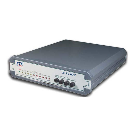
- Page 1 User Manual ETU01 ETU01-U Single Port G.703 E1 Access Unit CTC Union Technologies Co., Ltd.
- Page 3 ETU01-110 fixed 110-120VAC model ETU01-220 fixed 220-240VAC model ETU01-48 DC –48V model ETU01-AC version 2 universal AC model ETU01-DC version 2 universal (18~72V) DC model ETU01-DC version 2 (18~36V) DC model ETU01-DC version 2 (36~72V) DC model ETU01U-AC unframed E1, universal AC model...
-
Page 5: Table Of Contents
Table of Contents Chapter 1. Introduction …………………....9 1.1 Technical Specifications ………………………………… 9 1.2 E1 Signal Structure ……………………………………… 13 1.3 ETU-01 Capabilities …………………………………….. 15 1.4 System Timing Considerations …………………………. 16 1.5 Functional Description ………………………………….. 22 1.6 Typical System Applications …………………………… 27 Chapter 2. - Page 6 Table of Contents Chapter 5. Troubleshooting …………………………. 49 5.1 Equipment and Tools ………………………………….. 49 5.2 Visual Inspection ………………………………………. 49 5.3 Voltages and Current Checks ………………………….. 49 5.4 Internal Tests …………………………………………… 50 5.5 Self Test ……………………………………………….. 53 5.6 Functional Tests ……………………………………….. 55 5.7 Front Panel Switch Test ………………………………..
- Page 7 Table of Contents Appendix C. Interface Connections …………………………… 79 C.1 E1 Line Connectors ……………………………………. 79 C.2 E1 Line Frame Ground ………………………………… 81 C.3 X.21 User Data Channel Connector …………………… 82 C.4 RS-232 User Data Channel Connector ………………… 83 C.5 V.35 User Data Channel Connector …………………… 84 C.6 RS-530 User Data Channel Connector …………………...
- Page 8 Table of Contents This page left blank intentionally.
-
Page 9: Chapter 1. Introduction
Chapter 1. Introduction 1-1. Technical Specifications E1 link Framing -Unframed (ETU-01U only Unframed) -CCS (PCM31)/CAS (PCM30) -CRC4 ON/OFF Bit Rate 2.048 Mbps Line Code -AMI -HDB3 Line Impedance -75 ohms -120 ohms Relative Receive Level 0 to -43dB “Pulse” Amplitude -Nominal 2.37V±10% for 75 ohms -Nominal 3.00V±10% for 120 ohms ±0.1V... - Page 10 Chapter 1. Introduction User Data Channels Interface Types -V.35 -RS-449 -G.703/NRZ -X.21 -RS-232 -ET10 -RS-530 -G.703/64K -ET10R Interface Connectors V.35 Interface 34 pin, M-Block Female X.21 Interface 15 pin, D-type Female RS-530 Interface 25 pin, D-type Female RS-449 Interface 37 pin, D-type Male(adapter cable) RS-232 Interface 25 pin, D-type Female G.703/64K Interface...
- Page 11 Chapter 1. Introduction Diagnostics Test Switches/Diagnostics -Digital local loop back -Analog local loop back -Digital remote loop back -Test pattern / generator LED indicators Green Power Yellow Transmit data Yellow Receive data Yellow Request to sent Yellow Data carrier detect Tx CLK Loss Red Transmit clock loss Sig Loss...
- Page 12 Chapter 1. Introduction Power supply Voltage 110VAC±10% (AC 110 model) 220VAC±10% (AC 220 model) -48VDC ±6V (DC –48V model) Voltage (version 2) 90~250VAC (universal AC model) 18~72VDC (universal DC model) 18~36VDC (24V model) 36~72VDC (48V model) Frequency 47 to 63 Hz for AC Power consumption 20 Watts Fuse (version 1)
-
Page 13: E1 Signal Structure
Chapter 1. Introduction 1-2. E1 signal structure The E1 line operates at a nominal rate of 2.048Mbps. The data transferred over the E1 line is organized into frames, with each E1 frame containing 256 bits. The 256 bits consist of 32 time slots of eight bits each, which carry the data payload. - Page 14 Chapter 1. Introduction Multi-Frame Alignment Signal (MFAS) MFAS framing uses Channel Associated Signaling (CAS) to transmit A/B/C/D bit signaling information for each of 30 channels. This method uses the 32 time slot frame format with time slot 0 for the FAS and time slot 16 for the Multi-Frame Alignment Signal and the Channel Associated Signaling.
-
Page 15: Etu-01 Capabilities
Chapter 1. Introduction 1-3. ETU-01 Capabilities E1 link line coding The ETU-01 and ETU-01U support two E1 line codes: AMI coding. HDB3 coding. E1 framing formats The ETU-01 supports three formats: Unframed format. FAS (CCS, PCM-31) format. MFAS (CAS, PCM-30) format. The ETU-01U supports only unframed format. -
Page 16: System Timing Considerations
Chapter 1. Introduction 1-4. System Timing Considerations The ETU-01 has the flexibility to meet the timing requirements of various system configurations. The timing mode for the E1 link and the user data channel are selected by the setting of DIP switches. E1 link timing The ETU-01 E1 link receive path always operates on the receive clock. - Page 17 Chapter 1. Introduction • External timing: The ETU-01 E1 link transmit clock is locked to the clock signal provided by the user DCE connected to the data channel. When the data channel is used as the clock source, the data channel must use clock timing mode 3 (DTE2) or 4 (DTE3).
- Page 18 Chapter 1. Introduction • Clock mode 1 (DCE 2): The ETU-01 data channel operates as a DCE and provides both transmit and receive clocks (internal oscillator timing) to the data terminal equipment connected to the user channel. The clocks are locked to the oscillator timing. Clock Mode 1: Internal Connected Equipt.
- Page 19 Chapter 1. Introduction • Clock mode 2 (DTE 1): The ETU-01 data channel is physically wired as DCE (classed as communication equipment). However, the ETU-01 may operate as a DTE when connected to other DCE equipment by using a cross-over data cable and by setting the clock mode to the DTE1 setting.
- Page 20 Chapter 1. Introduction • Clock mode 3 (DTE 2): The ETU-01 data channel is physically wired as DCE (classed as communication equipment). However, the ETU-01 may operate as a DTE when connected to other DCE equipment by using a cross-over data cable and by setting the clock mode to the DTE2 setting.
- Page 21 Chapter 1. Introduction • Clock mode 4 (DTE 3): The ETU-01 data channel is physically wired as DCE (classed as communication equipment). However, the ETU-01 may operate as a DTE when connected to other DCE equipment by using a cross-over data cable and by setting the clock mode to the DTE3 setting.
-
Page 22: Functional Description
Chapter 1. Introduction 1-5. Functional Description The ETU-01 is a single port access unit for E1, Fractional E1 or Fractional cascade E1 service. The ETU-01U is a single port access unit for Unframed E1 only. The ETU-01 version 2 is functionally identical to the original ETU-01 except for the input power section. - Page 23 Chapter 1. Introduction At the time of this printing, the ETU-01 has nine types of user- replaceable data channel modules. 1. ETU/TTU-V35 V.35 Module: Provides one fully compliant ITU-T V.35 interface on a Female "M" block, 34 pin connector. Operates at any n56/n64 fractional or unframed E1 speed.
- Page 24 Chapter 1. Introduction 4. ETU/TTU-X21 X.21 Module: Provides one fully compliant ITU-T X.21 interface on a female "D" type 15 pin connector. Operates at any n56/n64 fractional or unframed E1 speed. 5. ETU/TTU-232 RS-232 Module: Provides one fully compliant EIA RS- 232 SYNC interface on a female "D"...
- Page 25 Chapter 1. Introduction 7. ETU/TTU-NRZ NRZ Module: Provides one NRZ interface on four(4) female type connectors. Operates at any n56/n64 fractional or unframed E1 speed. 8. ETU/TTU-ET10/100 Ethernet Bridge Module: Utilizes standard pin out on one RJ-45 connector, providing connection to Ethernet (10Base-T) or Fast Ethernet (100Base-TX) networks utilizing UTP (unshielded twisted pair) cabling.
- Page 26 Chapter 1. Introduction The ETU-01 features V.54 diagnostic capabilities for performing local loop back and remote digital loop back. The operator at either end of the line may test both the ETU-01 and the line in the digital loop back mode. The loop back is controlled by either a manual switch or by the DTE interface for V.35 and RS-530.
-
Page 27: Typical System Applications
Chapter 1. Introduction 1-6. Typical System Applications General The fractional E1 data service is based on the assumption that the user data rate is a fraction of the available E1 bandwidth, in multiples of 56K or 64K. In a typical application (Figure 1- 1a), the ETU-01 is used to connect the synchronous user DTEs over an E1 network or line. - Page 28 Chapter 1. Introduction In the previous applications, the ETU-01 is connected to an E1 network or to an up stream provider. In these cases the E1 timing will be set to “Recovery”. In the following examples, one unit will provide the E1 timing either by using its internal oscillator or from the connected DCE equipment.
-
Page 29: Chapter 2. Installation
Chapter 2. Installation 2-1. General This chapter provides detailed instructions for mechanical installation of the ETU-01. Following the completion of installation, please refer to Chapter 3 for operating information. 2-2. Site Preparation Install the ETU-01 within reach of an easily accessible grounded AC outlet. - Page 30 Chapter 2. Installation The AC line fuse is located in an integral-type fuse holder on the rear panel. Make sure that only fuses of the required rating are used for replacement. Do not use repaired fuses or short- circuit the fuse holder. The power cable must be disconnected before removing or replacing fuses.
- Page 31 Chapter 2. Installation E1 Line DB-15 Connector The pin assignment for DB-15 connector is as follows: Pin: Function: TTIP (Transmit data out) TRING (Transmit data out) RTIP (Receive data in) RRING (Receive data in) BNC coax connector Two BNC coax connectors marked RX and TX (Same function as the E1 line DB15 connector).
- Page 32 Chapter 2. Installation Cable and Termination Use a shielded twisted pair cable between the ETU-01 and the DTE device. The receivers on the ETU-01 are 100 Ohm terminated (For X.21 and RS-530). If problems are encountered with the connection to the DTE interface, make sure that the DTE interface is terminated correctly.
-
Page 33: Dip Switches And Jumpers Installation
Chapter 2. Installation 2-5. DIP Switches & Jumper Settings 2-5-1. Caution To avoid accidental electric shock, disconnect the ETU-01 power cord before opening the cover. Access inside the equipment is only permitted to authorized and qualified service personnel. 2-5-2. Procedure Turn power OFF, Disconnect the power cord from the AC outlet. - Page 34 Chapter 2. Installation Table 2-1 Item Function Possible Settings Set Place Factory Setting Sets the E1 framing Framed or Unframed DIPSW1-1 Framed Sets the active timeslots TS1 to TS31 random setting DIPSW2-2 to DIPSW4-8 TS1 to TS31 Sets the timing mode M0 (MODE0) to M4 (MODE4) DIPSW5-1 to DIPSW5-3 MODE0 (DCE1)
- Page 35 Chapter 2. Installation ETU-01 DIP Switches, Version 1.1 PCB...
- Page 36 Chapter 2. Installation ETU-01U DIP N.A. ETU-01 and ETU-01U DIP Switches, Version 2.1 PCB...
-
Page 37: Rack Mount Installation
Each rack mount kit provides all the necessary hardware for a complete installation. Figure 3-1: Rack Mount Installation, ETU01-SS. In single unit installations, the unit may be placed in the left or right side position simply by reversing the rack mounting “ears”. The kit includes, one (1) short and one (1) long rack adapter, four (4) 3x8mm self-tapping screws, and four (4) #12-24x0.5”... - Page 38 Chapter 2. Installation In order to save rack mount space, units may be mounted in tandem. Please refer to the following drawing examples for this application. Figure 3-2: Tandem Units Mounting (Exploded) Figure 3-3: Tandem Units Mounting Detail The tandem kit includes two (2) rack mount adapters, one (1) each of inner and outer central mounting adapters, twenty (20) 3x8mm self-tapping screws, and four (4) #12-24x0.5”...
-
Page 39: Chapter 3. Operation
Chapter 3. Operation 3-1. General This chapter describes the ETU-01 controls and indicators, explains operating procedures, and supplies instructions for field strapping changes. Installation procedures (in chapters 2) must be completed and checked before attempting to operate the ETU- 3-2. Controls and Indicators All controls (push-button switches) and LED indicators are located on the ETU-01 front panel. - Page 40 Chapter 3. Operation Table 3-1 Control Functions Item Control Switch Function Loc dig loopbk The local digital loop back switch causes local ETU-01 loop received data to its transmitter. Loc ana loopbk The local analog loop back switch causes local ETU-01 loop transmitter output back to its receiver.
- Page 41 Chapter 3. Operation Table 3-2 LED indicators Item Indicator Color Function Green ON when power is on. Yellow ON when SPACE is being transmitted. Flashing when data is transmitted. Yellow ON when SPACE is being received. Flashing when data is received. Yellow ON when terminal activates Request To Sent.
-
Page 42: Operating Procedure
Chapter 3. Operation 3-3. Operating Procedure The ETU-01 requires no operator attention once installed, except for occasional monitoring of the front panel indicators. Intervention is only required when: • The ETU-01 has to be adapted to new operational requirements. • Diagnostic loops are required. The ETU-01 is turned on when its AC power cord (or central office DC power) is connected to an AC power outlet (or the DC input connections) and the power switch is turned to the... -
Page 43: Chapter 4. Test And Diagnostics
Chapter 4. Test & Diagnostics 4-1. General This chapter contains procedures for performing system diagnostic tests. 4-2. Loop Back Tests The loop back test buttons (Loc dig loopbk, Loc ana loopbk and Rem loopbk) and the LED indicators built into the ETU-01 allow for rapid checking of the data terminal, ETU-01 and the E1 line. - Page 44 Chapter 4. Test & Diagnostics In this example, both units at the ends of the E1 link have their pattern generators enabled. Pattern Depressed Pattern Pattern Generator Tester External BERT Link Pattern Pattern Tester Generator ETU-01 ETU-01 Pattern Depressed Figure 4-1 BERT operation...
-
Page 45: Local Analog Loop Back
Chapter 4. Test & Diagnostics 4-4. Local Analog Loop Back This test is activated by depressing the “Loc ana loopbk” button. This test checks the performance of the ETU-01, the local data terminal and the connections between them. It is performed separately at the local and the remote sites (see Figure 4-2): Loc ana loopbk... -
Page 46: Local Digital Loop Back
Chapter 4. Test & Diagnostics 4-5. Local Digital Loop Back This test is activated by depressing the “Loc dig loopbk” button. The test consists of looping the received data back to the remote ETU-01. This test checks the performance of the local ETU-01, the remote ETU-01 and the connections between them (see Figure 4-3). -
Page 47: Remote Digital Loop Back
Chapter 4. Test & Diagnostics 4-6. Remote Digital Loop Back This test is activated by depressing the “Rem loopbk” push button. The test determines the performance both of the local and the remote ETU-01 units, as well as their interconnecting lines. The remote digital loop back test consists of providing a loop back at the remote ETU-01 (see Figure 4-4). - Page 48 Chapter 4. Test & Diagnostics Loop back test notes: 1. Quick test - standalone unit; With the E1 timing source set to internal oscillator, connect the E1 Tx to E1 Rx with a single coaxial cable. Press the Pattern/test switch. The E1 Tx and Rx circuits will be tested and pass if no error LED is lit.
-
Page 49: Chapter 5. Troubleshooting
Chapter 5. Troubleshooting 1. Equipment and tools required: 1-1. Oscilloscope, V.O.M., and HCT-6000 (1 each). 1-2. BNC and RJ-45 (or BANTAM) cables (1 each). 1-3. AC or DC power cable (1 each). 1-4. RS-530 Interface and DB25 (F)<->DB25 (M) cable. 1-5. -
Page 50: Internal Tests
Chapter 5. Troubleshooting 4. Internal tests: 4-1. Self test Press and hold SW1. Turn power ON. After one second release SW1. LEDs should appear as indicated below: LED1 LED2 LED3 LED4 LED5 LED6 TxClkLos LED7 LED8 LED9 LED10 LED11 LED12 Sig Loss Sync Loss Alarm... - Page 51 Chapter 5. Troubleshooting 4-4. Determine the E1/T1 drive IC Version No. Pressing SW1 again causes the LEDs to display drive IC Version No.: LED1 LED2 LED3 LED4 LED5 LED6 TxClkLos LED7 LED8 LED9 LED10 LED11 LED12 Sig Loss Sync Loss Alarm Error Test...
- Page 52 Chapter 5. Troubleshooting 4-7. LED test Pressing SW1 again enters the LED test: LED1 LED2 LED3 LED4 LED5 LED6 TxClkLos LED7 LED8 LED9 LED10 LED11 LED12 Sig Loss Sync Loss Alarm Error Test Self Test LED2~LED12 flash in sequence, all LEDs flash 5 times then repeat. 4-8.
-
Page 53: Self Test
Chapter 5. Troubleshooting 5. Self test (Data port interface disconnected or DIP switch setting wrong): 5-1. DATA PORT disconnected, LED error display: LED1 LED2 LED3 LED4 LED5 LED6 TxClkLos LED7 LED8 LED9 LED10 LED11 LED12 Sig Loss Sync Loss Alarm Error Test Self Test... - Page 54 Chapter 5. Troubleshooting 5-5. IN CAS (PCM30) ERROR, TIMESLOT16 ON, LED display: LED1 LED2 LED3 LED4 LED5 LED6 TxClkLos LED7 LED8 LED9 LED10 LED11 LED12 Sig Loss Sync Loss Alarm Error Test Self Test 6. Unit test(A) 6-1. Set HCT6000 with ETU-01 data port connected. 6-2.
-
Page 55: Functional Tests
Chapter 5. Troubleshooting 6-8. Use an oscilloscope to measure the G.703 E1 wave shape. Set scope to 0.1V/DIV horizontal and 0.2us/DIV vertical, and set the probe to 10X. Attach probe to test point at CN2, DB15 pin1 and pin 9. The wave shape should be in the 3 volt range. - Page 56 Chapter 5. Troubleshooting 7-7. Use an oscilloscope to measure the G703 E1 wave shape. Set scope to 0.1V/DIV horizontal and 0.2us/DIV vertical, and set the probe to 10X. Attach probe to test point at CN2, DB15 pin1 and pin 9. The wave shape should be approximately 2.37V.
-
Page 57: Front Panel Switch Test
Chapter 5. Troubleshooting 9-2. Set the ETU-01 DIPSW setting per table on page 45: 9-3. Turn ON ETU-01 power, press RUN on the HCT6000. The HCT6000 should run without error, wait for 20 seconds. The ETU-01 LED display should display: LED1 LED2 LED3... - Page 58 Chapter 5. Troubleshooting 10-4.On the ETU-01, press the ”Pattern” button. The HCT6000 should continue to run without error. The ETU-01 LED display will show: LED1 LED2 LED3 LED4 LED5 LED6 TxClkLos FLASH FLASH LED7 LED8 LED9 LED10 LED11 LED12 Sig Loss Sync Loss Alarm Error...
- Page 59 Chapter 5. Troubleshooting Initial settings for 3-2 under voltage / current tests: ON OFF ON OFF...
- Page 60 Chapter 5. Troubleshooting Settings for Unit test (A), 6-4: ON OFF ON OFF...
- Page 61 Chapter 5. Troubleshooting Settings for Unit test (B), 7-3: ON OFF ON OFF...
- Page 62 Chapter 5. Troubleshooting Settings for Unit test (C), 8-2: ON OFF ON OFF...
- Page 63 Chapter 5. Troubleshooting Settings for Unit test (D), 9-2: ON OFF ON OFF...
- Page 64 Chapter 5. Troubleshooting Setting for front panel switch function, 10-2: ON OFF ON OFF...
-
Page 65: Factory Default Settings
Chapter 5. Troubleshooting Setting for factory defaults, 11-1: ON OFF ON OFF... - Page 66 Chapter 5. Troubleshooting Troubleshooting Notes:...
-
Page 67: Appendix A. Dip Switch Setting Etu-01
Appendix A. DIP SW. Setting ETU-01 A-1 All DIP SW. Function Description DIP SW FUNCTION COMMENT Time slot 0 to 7 setting See Table A-2 Time slot 8 to 15 setting See Table A-3 Time slot 16 to 23 setting See Table A-4 Time slot 24 to 31 setting See Table A-5... -
Page 68: Dip Sw1 Time Slot 0 To 7 Setting
Appendix A. DIP SW. Setting ETU-01 A-2 DIP SW1 Time Slot 0 To 7 Setting STATE FUNCTION COMMENT DIP SW1 Unframed mode Note 1 Framed mode Note 2 Time slot 1 disable Time slot 1 enable Time slot 2 disable Time slot 2 enable Time slot 3 disable Time slot 3 enable... -
Page 69: Dip Sw2 Time Slot 8 To 15 Setting
Appendix A. DIP SW. Setting ETU-01 A-3 DIP SW2 Time Slot 8 To 15 Setting STATE FUNCTION COMMENT DIP SW2 Time slot 8 disable Time slot 8 enable Time slot 9 disable Time slot 9 enable Time slot 10 disable Time slot 10 enable Time slot 11 disable Time slot 11 enable... -
Page 70: Dip Sw3 Time Slot 16 To 23 Setting
Appendix A. DIP SW. Setting ETU-01 A-4 DIP SW3 Time Slot 16 To 23 Setting STATE FUNCTION COMMENT DIP SW3 Time slot 16 disable Time slot 16 enable Note 1 Time slot 17 disable Time slot 17 enable Time slot 18 disable Time slot 18 enable Time slot 19 disable Time slot 19 enable... -
Page 71: Dip Sw4 Time Slot 24 To 31 Setting
Appendix A. DIP SW. Setting ETU-01 A-5 DIP SW4 Time Slot 24 To 31 Setting STATE FUNCTION COMMENT DIP SW4 Time slot 24 disable Time slot 24 enable Time slot 25 disable Time slot 25 enable Time slot 26 disable Time slot 26 enable Time slot 27 disable Time slot 27 enable... -
Page 72: Dip Sw5 Parameter Group 1 Setting
Appendix A. DIP SW. Setting ETU-01 A-6 DIP SW5 Parameter Group 1 Setting STATE FUNCTION COMMENT DIP SW5 -1,-2,-3 Clock mode 0 (DCE1) See Table A-9 OFF OFF OFF Clock mode 1 (DCE1) ON OFF OFF Clock mode 2 (DTE1) OFF ON OFF Clock mode 3 (DTE2) ON OFF... -
Page 73: Dip Sw6 Parameter Group 2 Setting
Appendix A. DIP SW. Setting ETU-01 A-7 DIP SW6 Parameter Group 2 Setting STATE FUNCTION COMMENT DIP SW6 Jitter attenuator: Disable Jitter attenuator: Enable Jitter place in: Received side Jitter place in: Transmitted side Jitter buffer depth: 32 bits Jitter buffer depth: 128 bits Multiplex (cascade): Disable Multiplex (cascade): Enable TS16: Nonpassthrough... -
Page 74: Clock Mode Description
Appendix A. DIP SW. Setting ETU-01 A-9 Clock Mode Description CLOCK DIPSW 5 E1 LINE USER DATA PORT MODE STATE TRANSMIT RECEIVE TRANSMIT CLOCK CLOCK CLOCK OFF OFF OFF RECOVERY RECOVERY RECOVERY Output to RC pin Output to TC pin (DCE1) OFF OFF INTERNAL INTERNAL... -
Page 75: Appendix B. Dip Switch Setting Etu-01U
Appendix B. DIP SW. Setting ETU-01U B-1 All DIP SW. Functional Description DIP SW FUNCTION COMMENT Not Applicable Unframed Only Not Applicable Unframed Only Not Applicable Unframed Only Not Applicable Unframed Only Parameter group 1 setting See Table B-2 Parameter group 2 setting See Table B-3 Line impedance setting See Table B-4... -
Page 76: Dip Sw5 Parameter Group 1 Setting
Appendix B. DIP SW. Setting ETU-01U B-2 DIP SW5 Parameter Group 1 Setting STATE FUNCTION COMMENT DIP SW5 -1,-2,-3 Clock mode 0 (DCE1) See Table B-5 OFF OFF OFF Clock mode 1 (DCE1) ON OFF OFF Clock mode 2 (DTE1) OFF ON OFF Clock mode 3 (DTE2) ON OFF... -
Page 77: Dip Sw6 Parameter Group 2 Setting
Appendix B. DIP SW. Setting ETU-01U B-3 DIP SW6 Parameter Group 2 Setting STATE FUNCTION COMMENT DIP SW6 Jitter attenuator: Disable Jitter attenuator: Enable Jitter place in: Received side Jitter place in: Transmitted side Jitter buffer depth: 32 bits Jitter buffer depth: 128 bits Don’t care Don’t care Don’t care... -
Page 78: Clock Mode Description
Appendix B. DIP SW. Setting ETU-01U B-5 Clock Mode Description CLOCK DIPSW 5 E1 LINE USER DATA PORT MODE STATE TRANSMIT RECEIVE TRANSMIT CLOCK CLOCK CLOCK OFF OFF OFF RECOVERY RECOVERY RECOVERY Output to RC pin Output to TC pin (DCE1) OFF OFF INTERNAL INTERNAL... -
Page 79: Appendix C. Interface Connections
Appendix C. Interface Connections C-1. E1 Line Connectors C-1.1 DB-15 connector The E1 link DB-15 connector conforms to AT&T Pub 62411. The physical interface is a 15-pin female D-type connector. Designation Direction Function TTIP From ETU-01 Transmit data(+) ↔ Frame ground RTIP To ETU-01 Receive data(+) - Page 80 Appendix C. Interface Connections C-1.2 BNC connector Conn. Designation Direction Function Center TTIP From ETU-01 Transmit data ↔ Sleeve TRING Signal return Center RTIP To ETU-01 Receive data ↔ Sleeve RRING Signal return Table C-2 E1 BNC connector pin allocation C-1.3 BANTAM connector (on Ver.
-
Page 81: E1 Line Frame Ground
Appendix C. Interface Connections C-2. E1 Line Frame Ground To enable Frame Ground (Chassis) connections to the E1 signal carrying lines, place solder shorts at the locations on the bottom trace side of the printed circuit board. Factory default is no FG connection. By default this ground is not connected. -
Page 82: X.21 User Data Channel Connector
Appendix C. Interface Connections C-3. X.21 Data Module Connector When the ETU-01 is ordered with an X.21 interface, the physical interface is a 15-pin female D-type connector wired in accordance with Table C-5. SIGNAL PIN CIRCUIT DIRECTION DESCRIPTION FUNCTION Protective Shield Chassis ground. -
Page 83: Rs-232 User Data Channel Connector
Appendix C. Interface Connections C-4. RS-232 Data Module Connector When the ETU-01 is ordered with a RS-232 interface, the physical interface is a 25-pin female D-type connector wired in accordance with Table C-6. SIGNAL CIRCUIT DIRECTION DESCRIPTION FUNCTION Shield Chassis ground. May be isolated from signal ground. -
Page 84: V.35 User Data Channel Connector
Appendix C. Interface Connections C-5. V.35 Data Module Connector When the ETU-01 is ordered with a V.35 interface, the physical interface is a 34-pin female M-type connector wired in accordance with Table C-7. SIGNAL CIRCUIT DIRECTION DESCRIPTION FUNCTION Protective Frame Chassis ground. -
Page 85: Rs-530 User Data Channel Connector
Appendix C. Interface Connections C-6. RS-530 Data Module Connector When the ETU-01 is ordered with an RS-530 interface, the physical interface is a 25-pin female D-type connector wired in accordance with Table C-8. SIGNAL CIRCUIT DIRECTION DESCRIPTION FUNCTION Protective Frame Chassis ground. -
Page 86: Rs-530 To Rs-449 Adapter Cable
Appendix C. Interface Connections C-7. RS-530 to RS-449 Adapter Cable When the ETU-01 is ordered with a RS-449 interface, the physical interface is a 37-pin male D-type connector wired in accordance with Table C-9. SIGNAL RS-530 RS-449 RS-449 DESCRIPTION FUNCTION CIRCUIT Protective Chassis ground. -
Page 87: G.703/64K Codirectional Connector
Appendix C. Interface Connections C.8 G.703/64K Codirectional Connector When the ETU-01 is ordered with a G.703/64K interface, the physical interface is a 15-pin female D-type connector wired in accordance with Table C-10. SIGNAL DIRECTION DESCRIPTION FUNCTION Protective Chassis ground. Ground May be isolated from Signal Ground. -
Page 88: G.703 Nrz Connectors
Appendix C. Interface Connections C.9 G.703 NRZ When the ETU-01 is ordered with a G.703 NRZ interface, the physical interface is 4 BNC female connectors wired in accordance with Table C-11. Specifications: Line Code: Impedance: 50 ohms Signal Level: Logic "1": 0V +/- 0.3V Logic "0": -1.5V +/- 0.3V Speed: 2048K Max. -
Page 89: Et10 10Base-T Ethernet Bridge
Appendix C. Interface Connections C.10 ET10 10BASE-T Ethernet Interface (legacy interface, discontinued) When the ETU-01 is ordered with an ET10 Interface, the unit is not only an access unit for E1, but also becomes a high performance WAN bridge 10Base-T Ethernet extension. -
Page 90: Et10/100 10/100Base-Tx Ethernet Bridge
Appendix C. Interface Connections C.11 ET10/100 10/100BASE-TX Ethernet Interface When the ETU-01 is ordered with an ET10/100 Interface, the unit is not only an access unit for E1, but also becomes a high performance WAN bridge for 10Base-T or 100Base-TX Ethernet extension. -
Page 91: Et10R 10/100Base-Tx Ethernet Router
Appendix C. Interface Connections C.12 ET100R 10/100BASE-TX Ethernet Router When the ETU-01 is ordered with an ET100R Interface, the unit is not only an access unit for E1, but also becomes a high performance Router for 10Base-T or 100Base-TX Ethernet LAN connection. - Page 92 Appendix C. Interface Connections...
- Page 93 CTC Union Technologies Inc Fax:(886)2 27991355 Tel:(886)2 26591021 Attn : Technical Support Division E-mail:info@ctcu.com From Company: Name: Tel: ( Fax:( MODEL: ETU-01 ETU-01U ACTIVITY: As attached in DIP switch setting table SYS CONFIGURATION: Question:...
-
Page 94: Technical Inquiry Form
Technical Inquiry Form MODEL No.: ETU-01 ETU-01U Please fill in the DIP switches configuration with ' ' marks into the following table. Send it to us by fax, and we will reply to you immediately. Your Setting CTC Suggestion SW NO. FUNCTION Unframed/ framed Timeslot 1... - Page 95 Your Setting CTC Suggestion SW NO. FUNCTION Jitter Attenuator Jitter Place In Jitter Buffer Depth Multiplex (cascade) TS16 Pass Through Reserved Data Port Loop Back Front panel switch Enable E1 Line Impedance E1 Line Impedance E1 Line Impedance E1 Line Impedance E1 Line Impedance Please advise any additional comments:...
- Page 98 CTC Union Technologies Co., Ltd. Far Eastern Vienna Technology Center (Neihu Technology Park) 8F, No. 60 Zhouzi Street Neihu District, Taipei, Taiwan Phone:(886) 2.2659.1021 (Rep) Fax:(886) 2.2799.1355 info@ctcu.com http://www.ctcu.com E-mail:...
Need help?
Do you have a question about the ETU01 and is the answer not in the manual?
Questions and answers