Table of Contents
Advertisement
Advertisement
Table of Contents

Subscribe to Our Youtube Channel
Related Manuals for K-TEK AccuTrak AT100


Summary of Contents for K-TEK AccuTrak AT100
-
Page 2: Table Of Contents
TABLE OF CONTENTS 1.0 INTRODUCTION ............................... 4 2.0 STORAGE INFORMATION ..........................5 3.0 INSTALLATION AND BASIC WIRING ......................5 3.1 All Installations ..........................5 3.1.1 Compression Fittings ......................5 3.1.2 Floats ............................ 5 3.1.3 Transmitter Housing Height ....................5 3.2 Stilling Probes ..........................5 3.2.1 Assembly Instructions for F1 Flexible Probes ............... - Page 3 TABLE OF CONTENTS (continued) 5.3.8 PID Blocks ............................18 5.3.9 Link Active Scheduler / Back-up LAS ..................18 5.3.10 Threshold Adjustment ......................18 5.3.11 Sample Configurations ......................18 6.0 SAFETY, MAINTENANCE, & TROUBLESHOOTING ..................19 6.1 Personnel Qualifications ....................... 19 6.2 Required Tools ..........................
-
Page 4: Introduction
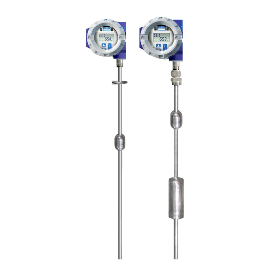
High accuracy and no maintenance are two of the most common reasons for choosing this technology. With optional ratings to 800°F (427°C) and 3000 PSI (207 bar), K-TEK's Magnetostrictive Level Transmitters are suitable for almost any application. HART, Honeywell DE, and Foundation Fieldbus Protocol options make our AT100‟s easy to connect digitally to most control systems. -
Page 5: Storage Information
2.0 STORAGE INFORMATION If required, storage prior to installation should be indoors at ambient temperature, not to exceed the following: Temperature range: -40º- 150ºF (-40º- 66ºC) Humidity: 0 to 95% R.H. non-condensing. WARNING: Transmitter probes with /SW3 option have a flexible stainless steel sensor tube which is not hermetically sealed. -
Page 6: Assembly Instructions For F1 Flexible Probes
3.0 INSTALLATION AND BASIC WIRING 3.2.1 Assembly Instructions for F1 Flexible Probes Refer to Appendix B for /F1 Option Assembly Drawing 1. Prepare joints #2 and #3 by lubricating the O-Ring and mating surface. 2. Lower the bottom tube section with the float stop and float into the tank. 3. -
Page 7: Transmitter Calibration And Setup
4.0 TRANSMITTER CALIBRATION AND SETUP 4.1 Level Output Calibration The AT100 is a digital transmitter with no routine calibration required. If re-calibration is required, calibration can be changed using the module pushbuttons, a HART communicator (for units with the HART option), or with the menu driven LCD readout (for units with LCD option). - Page 8 AT100 Menu Flow Chart MAIN DISPLAY CAL - Calibration Menu CFG - Configuration Menu LRV - Lower Range Value DE MENU - MENU LL1 - Liquid Level 1 LRC - Lower Range Current PV= - Process Variable L1C - Level 1 Current URV - Upper Range Value EUN - Engineering Unit LL2 - Liquid Level 2...
-
Page 9: Calibration Using The Lcd Setup Menu
4.0 TRANSMITTER CALIBRATION AND SETUP Electronics Without Electronics With LCD Display LCD Display 4.4 Calibration Using the LCD Setup Menu The LCD Display option offers a menu driven setup that uses the UP, DOWN and SELECT pushbuttons. Refer to the menu flow chart for navigation and selection instructions. ... -
Page 10: Selecting An Engineering Unit For Measurement (Eun)
4.0 TRANSMITTER CALIBRATION AND SETUP 4.6 Selecting an Engineering Unit for Measurement (EUN) The unit is capable of displaying level output in inches, feet, millimeters, centimeters, meters, or in percent of range. Selecting an Engineering Unit -Under the CFG menu, go to the EUN menu option. -Press SELECT, then press UP or DOWN to cycle between engineering units. -
Page 11: Temperature Output Calibration
4.0 TRANSMITTER CALIBRATION AND SETUP 4.9.2 Temperature Output Calibration The transmitter is factory calibrated to an accuracy of ±0.5° Celsius, over a range of -200 to 300°C. Fine calibration and trim for a custom range can be done via the following steps: ... -
Page 12: Volumetric Strapping
4.0 TRANSMITTER CALIBRATION AND SETUP 4.10 Volumetric Strapping Note: For AT100 models with Strapping Table option only. If utilizing Foundation Fieldbus refer to section 4.3.5.2 for strapping table instructions. 4.10.1 How the Strapping Table Works The AT strapping table works by using table points set up by the user. For every point, there is a volume (provided by the user) and a measurement (provided by either the user or the transmitter). -
Page 13: Setting Up Strapping Table Points
4.0 TRANSMITTER CALIBRATION AND SETUP 4.10.4 Setting Up Strapping Table Points Under the CAL menu: 1) Scroll to VOL TABL, then press SELECT. A) In manual mode, set the measured value for each Input Point and set the corresponding Output Point to the desired volume value. -
Page 14: Alarm Delay
4.0 TRANSMITTER CALIBRATION AND SETUP 4.11 Alarm Delay The AT100 transmitter is designed to send the current output into a Fail Safe mode when the transmitter does not detect a return signal from the sensor tube or the transmitter experiences a diagnostic failure. In certain installations (such as high vibration areas) the transmitter may experience sporadic interruptions in the return signal which are not an indication of sensor tube failure. -
Page 15: Communication Options
5.0 COMMUNICATION OPTIONS 5.1 HART Protocol Interface Option The K-TEK transmitter can be ordered with the HART Protocol Option, which is installed at the factory as a part of the electronic module assembly. When fitted with the HART Protocol Option, it will be possible to communicate with the transmitter using a Rosemount 268, 275, or 375 communicator utilizing slave mode. -
Page 16: Foundation Fieldbus
Spur 5.0 COMMUNICATION OPTIONS Junction Box Shield 5.3 Foundation Fieldbus Terminator 5.3.1 Topology Fieldbus Phase Power The device may be installed in either a Bus or Tree topology. Neutral Supply Coupler Ground Bus Topology Spur Junction Box Spur Spur Shield Analog Panel Ground... -
Page 17: Field Wiring
5.0 COMMUNICATION OPTIONS 5.3.3 Field Wiring All power to the transmitter is supplied over the signal wiring. Signal wiring should be a shielded, twisted pair for best results. Do not run unshielded signal wiring in conduit or open trays with power wiring or near heavy electrical equipment. -
Page 18: Pid Blocks
5.0 COMMUNICATION OPTIONS 5.3.8 PID Blocks The AT transmitter is equipped with 5 PID (Proportional, Integral, Derivative) Blocks. These blocks can be used to implement control algorithms within the transmitter. The output of the PID Block can be linked to the AO (Analog Output ) Block of another instrument like a valve or to the input of another PID Block. -
Page 19: Safety, Maintenance, & Troubleshooting
If a transmitter fails an inspection or assistance is required for inspection or troubleshooting, contact the Service Department at K-TEK Corporation via e-mail at service@ktekcorp.com. The Service Department will answer questions, provide additional assistance, and issue Return Authorization Numbers for equipment in need of repair. -
Page 20: Suggested Proof Test
Note: K-TEK floats are designed for different specific gravity ranges. The float may or may not float in the water. It may be necessary to hold the float under the water to perform this test. -
Page 21: Sensor Inspection
6.0 SAFETY, MAINTENANCE, AND TROUBLESHOOTING 6.4.2 Sensor Inspection The sensor of the AT100 consists of a metal tube containing several wires. The sensor tube will measure the float location properly if the tube is straight and the float can travel freely up and down its length. Perform a visual inspection on the sensor tube to make sure it is straight, free from pits or gouges, and does not show excessive wear patterns. - Page 22 6.0 SAFETY, MAINTENANCE, AND TROUBLESHOOTING 6.4.4.3 4-20mA Loop Check - Without HART With the transmitter installed, wired and powered in its field location, move the float up and down the length of the probe. Confirm the proper reading at the indication or control side of the loop. Move the float using the process fluid or some other mechanical means.
-
Page 23: 4-20Ma, Hart Transmitters
6.5 4-20mA, HART Transmitters Symptom Possible Problem Solution Display showing Threshold voltage too high Turn the threshold voltage adjustment counter-clockwise 1 full turn or follow **** the threshold adjustment procedure in Section 6.8 Unit in alarm Electronics module failure Replace the existing module with a known working module (20.97 or 3.61 Float missing or damaged Inspect float for presence or damage, if damaged contact the factory for... -
Page 24: Foundation Fieldbus Transmitters
6.0 SAFETY, MAINTENANCE, AND TROUBLESHOOTING 6.6 Foundation Fieldbus Transmitters Foundation Fieldbus transmitters operate using the same level measurement techniques as 4-20mA transmitters. This troubleshooting section only covers problems specific to Foundation Fieldbus setup and communications. Troubleshooting of the level indication from the Transducer Block may require the use of the 4- 20mA, HART troubleshooting section. -
Page 25: Verify Proper Power Up Of The Transmitter
6.0 SAFETY, MAINTENANCE, AND TROUBLESHOOTING During normal operation, it is not necessary to perform maintenance on the AT100 transmitter. Routine calibration of the transmitter is not necessary. The AT100 contains an EPROM which will store calibration in case of an outage or electronics replacement. 6.7 Verify Proper Power-up of the Transmitter Use a mA meter to measure the output current. -
Page 26: Threshold Adjustment
6.0 SAFETY, MAINTENANCE, AND TROUBLESHOOTING 6.9 Threshold Adjustment If the output occasionally jumps to an alarm condition (**** on display), this can be an indication of a loss of signal or a transmitter threshold voltage not set properly. The adjustment can be done as follows Note: It is preferable to make this adjustment with the float located towards the end of the sensing tube, away from the transmitter housing, but within the normal measuring range. -
Page 27: Threshold Adjustment Using An Oscilloscope
6.0 SAFETY, MAINTENANCE, AND TROUBLESHOOTING 6.12 Threshold Adjustment Using an Oscilloscope Principle of Operation: The main module in the AT housing performs 10 measurement cycles per second. 1. Start of cycle: A current pulse (Start Pulse) is applied to the sensor wire, which is under tension in the sensor tube. -
Page 28: Nametag Information
7.0 NAMETAG INFORMATION MADE IN USA MADE IN USA MADE IN USA MODEL NO: MODEL NO: MODEL NO: SERIAL / TAG NO: SERIAL / TAG NO: SERIAL / TAG NO: MAX TEMP - HOUSING: 170°F ; SENSOR: MAX TEMP - HOUSING: 170°F ; SENSOR: MAX TEMP - HOUSING: 170°F ;... -
Page 29: Wiring Diagrams
8.0 WIRING DIAGRAMS 8.1 FM/CSA AT100-0200-1 Rev L (10-2010) DCN0528... - Page 30 8.0 WIRING DIAGRAMS 8.1 FM/CSA (continued) AT100-0200-1 Rev L (10-2010) DCN0528...
-
Page 31: Atex/Iec
8.0 WIRING DIAGRAMS 8.2 ATEX/IEC AT100-0200-1 Rev L (10-2010) DCN0528... - Page 32 8.0 WIRING DIAGRAMS 8.2 ATEX/IEC (continued) AT100-0200-1 Rev L (10-2010) DCN0528...
-
Page 33: Typical Loop Wiring Diagram
8.0 WIRING DIAGRAMS 8.3 Typical Loop Wiring Diagram AT100-0200-1 Rev L (10-2010) DCN0528... -
Page 34: Loop Powered Tx Hookup /Ri Dual Compartment Housing
8.0 WIRING DIAGRAMS 8.4 Loop Powered TX Hookup /RI Dual Compartment Housing AT100-0200-1 Rev L (10-2010) DCN0528... -
Page 35: Temperature Simulation Wiring Diagram
8.0 WIRING DIAGRAMS 8.5 Temperature Simulation Wiring Diagram AT100-0200-1 Rev L (10-2010) DCN0528... -
Page 36: F1 Option Assembly Drawing
9.0 /F1 OPTION ASSEMBLY DRAWING AT100-0200-1 Rev L (10-2010) DCN0528... -
Page 37: Sil Certificate
10.0 SIL Certificate AT100-0200-1 Rev L (10-2010) DCN0528... - Page 38 10.0 SIL Certificate (continued) AT100-0200-1 Rev L (10-2010) DCN0528...
-
Page 39: Eu Declaration Of Conformity
11.0 EU DECLARATION OF CONFORMITY AT100-0200-1 Rev L (10-2010) DCN0528... -
Page 40: Warranty Statement
K-TEK will repair or replace, at K-TEK‟s election, defective items which are returned to K-TEK by the original purchaser within the period specified above from the shipment date of the item and which is found, upon examination by K-TEK, to its satisfaction, to contain defects in materials or workmanship which arose only under normal use and service and which were not the result of either alterations, misuse, abuse, improper or inadequate adjustments, applications or servicing of the product. - Page 41 AT100-0200-1 Rev L (10-2010) DCN0528...
Need help?
Do you have a question about the AccuTrak AT100 and is the answer not in the manual?
Questions and answers