Table of Contents
Advertisement
Advertisement
Table of Contents

Related Manuals for Ambient ASHP-23

Summary of Contents for Ambient ASHP-23
- Page 1 Installation and User Guide Models ASHP-23 ASHP-23-3P ASHP-23-HW ASHP-23-3P-HW ASHPCHW-23 ASHPCHW-23-3P ASHPPOOL-23 ASHPPOOL-23-3P Ambient variable speed air to water reverse cycle heat pumps Quality Australian Made Product By Copyright AusGeothermal 2018 Page 1 of 38...
-
Page 2: Table Of Contents
Installation Guide Contents Cover page Contents 3-4. Introduction 5-11. Model selection Hydronic Buffer Tanks/Commercial Hot Water Tanks 13-17. Installation Options/Piping Schematics Packaging and Handling 19-20. Heat Pump Location and Mounting/Schematic 21-23. Wiring Diagram (Single Phase) (Three Phase) 24-26. Filling System 27-28. -
Page 3: Introduction
Introduction ✓ Thank you for purchasing our state of the art Ambient variable speed air to water heat pump. ✓ Ambient variable speed air to water heat pumps have been designed and manufactured with energy efficiency and ease of installation in mind. - Page 4 ✓ Ambient Variable Speed Air Source Heat Pump units can also be controlled via a wide range of external control devices including standard room controls, Innovum Heat View, Modbus, BACnet, SNMP, BMS etc ✓ Ambient Variable speed heat pumps can be used for a wide...
-
Page 5: Model Selection
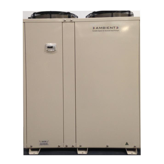
Model Selection Ambient Variable Speed Air Source Heat Pumps Are available in the below selection list by category Diagram/Photo Copyright AusGeothermal 2018 Page 5 of 38... - Page 6 Diagram/Photo Copyright AusGeothermal 2018 Page 6 of 38...
- Page 7 Commercial Hot Water Page 7 of 38...
- Page 8 Hydronic Heating Page 8 of 38...
- Page 9 Hydronic Heating Page 9 of 38...
- Page 10 Hydronic Heating Page 10 of 38...
- Page 11 Swimming Pool Heating Page 11 of 38...
-
Page 12: Hydronic Buffer Tanks/Commercial Hot Water Tanks
Hydronic Buffer Tanks Commercial Hot Water Tanks Model: ACHWTSS Dimension Fittings A Diameter 680mm Height 1860mm C Hot Water Outlet/PTR Valve/Ring Loop Return 1540mm D Sensor Port 1240mm DN20 Cold Water/Heat Pump In 200mm DN32 Boiler Return/Heat Pump Out DN32 G PTR Valve DN20 H Element-Upper Unit Thermostat Setting... - Page 13 Installation Options and Piping (Hydronic) AMBIENT WITH BUFFER TANK STORAGE ELECTRICAL SUPPLY ISOLATOR SENSOR POCKET HYDRONIC FLOW WATER OUT 1 INCH HYDRONIC FLOW WATER OUT 1 INCH HYDRONIC RETURN WATER IN 1 INCH HYDRONIC RETURN WATER IN 1 INCH COLD WATER FILL ½ INCH MBSP COLD WATER FILL ½...
- Page 14 PIPE SENSOR HYDRONIC RETURN WATER IN 1 INCH COLD WATER FILL ½ INCH MBSP 3 BAR PRESSURE RELIEF VALVE ½ INCH RETURN FROM HYDRONIC RADIATOR CIRCIT AMBIENT WITH FAN COIL HEATING/COOLING FLOW TO CHILLED/HOT WATER ELECTRICAL SUPPLY FAN COIL UNIT ISOLATOR...
- Page 15 Installation Options and Piping (Hydronic) AMBIENT WITH FAN COIL HEATING/COOLING AND SLAB HEATING FLOW TO CHILLED/HOT WATER FAN COIL UNIT ELECTRICAL SUPPLY ISOLATOR FLOW TO INFLOOR HEATING MANIFOLD DIVERTER VALVE ROOM CONTROLS TO WIRE BACK TO AMBIENT EXTERNAL SENSOR POCKET...
-
Page 16: Installation Options/Piping Schematics
Installation Options and Piping Commercial Hot Water HOT WATER OUT BOOST ELEMENT SPRING CHECK VALVE ELECTRICAL SUPPLY SENSOR ISOLATOR POCKET HOT WATER OUT HOT WATER IN COLD WATER FILL Diagram/Photo Copyright AusGeothermal 2018 Page 16 of 38... - Page 17 Installation Options and Piping Swimming Pool Heating ELECTRICAL SUPPLY ISOLATOR POOL WATER OUTLET RETURN TO POOL 50MM PVC POOL WATER INLET 50MM PVC FROM POOL HEATING PUMP/FILTER SYSTEM Diagram/Photo Copyright AusGeothermal 2018 Page 17 of 38...
-
Page 18: Packaging And Handling
Packaging and Handling Weight: 150KG Lifting device required Supplied on heavy duty shipping pallet Sealed within cardboard packaging and labels Package Dimensions 1600mm Height 1200mm Width 700mm Depth Important Prior to installing the heat pump please ensure to inspect the item for any visual damage *Above information provided based per one unit (heat pump) only Diagram/Photo Copyright AusGeothermal 2018... - Page 19 Heat Pump Location And Mounting ✓ It is important that the Ambient Variable Speed Air Source Heat Pump is installed so that the outside ambient air is not recirculated through the outdoor coil ✓ Ambient Variable Speed Air Source Heat Pumps are...
-
Page 20: Heat Pump Location And Mounting/Schematic
Heat Pump Location and Mounting Schematic Diagram/Photo Copyright AusGeothermal 2018 Page 20 of 38... -
Page 21: Wiring Diagram (Single Phase) (Three Phase)
Wiring Diagram Important – Wiring diagram is provided with each heat pump unit Diagram below: Single Phase Diagram/Photo Copyright AusGeothermal 2018 Page 21 of 38... - Page 22 Wiring Diagram Important – Wiring diagram is provided with each heat pump unit Diagram below: Three Phase Diagram/Photo Copyright AusGeothermal 2018 Page 22 of 38...
- Page 23 External control box (do not apply any external voltage to these digital input terminals) THERMOSTAT POWER INSTALL EXTERNAL REMOVE BRIDGE WIRE FOR FLOW SWICH BOOST INSTALLATION BUTTON IF REQUIRED REMOVE BRIDGE WIRE FOR EXTERNAL TERMOSTAT INSTALATION (e.g. EXTERNAL TERMOSTAT COMMON TO GND EXTERNAL THERMOSTAT N/O TO 1) 1 = N/O GND = COM...
-
Page 24: Filling System
Filling System Once the system has been correctly connected and installed as instruction provided here within to heating, cooling or hot water system, please start filling the system with fresh water ONLY Note If connecting to previously used hydronic heating, cooling or hot water system, it is important to make sure that heat pump is properly connected, this involves ensuring the heat pump is properly power flushed and cleaned effectively... - Page 25 Add appropriate closed-circuit corrosion inhibitor to all hydronic systems Add propylene glycol to reverse cycle hydronic cooling systems and heating systems in low ambient conditions For cooling application -10°C glycol freezing level is recommended and external flow switch to be fitted...
- Page 26 Filling System Continued Mains water supply on commercial hot water systems should not exceed 5.0 bar (500 Kpa) Pressure reduction valves must be fitted PTR valves (Pressure temperature relief valves) must be fitted and should not exceed 7.0 bar (700 Kpa) Page 26 of 38...
-
Page 27: Pre-Start Checks
Water shut off valves installed on unit Pressure limiting cold water inlet valves installed with correct back flow prevention Propylene glycol added to lower freezing point of hydronic circulation water in low ambient conditions and cooling applications For cooling applications -10 glycol freezing level is recommended... - Page 28 Pre-Start Checks Continued Closed circuit corrosion inhibitor installed in all hydronic systems System filled and air bled with fresh water only Pipe sizing and insulation installed to limit heat loss and vibration Leak check all piping Check system installation piping and wiring for neat visual and quality installation Installer Notes Page 28 of 38...
-
Page 29: Start-Up Procedure/Quick Start Up Procedure (Hydronic Heat Pump Units)
Start Up Procedure After Pre-Start checks are completed: ✓ Turn off system isolator on right hand side of the heat pump unit ✓ Remove front left hand electrical panel on the heat pump unit and turn on electrical circuit breakers within the heat pump unit electrical compartment ✓... - Page 30 Quick Start Procedure Hydronic Heat Pump Units ✓ Press the TARGET TEMP button The Settings screen will now be displayed ✓ Press Enter button and the curser will now be flashing Mode: OFF ✓ Press the UP or DOWN arrows to select HEAT ONLY, COOL ONLY or OFF ✓...
-
Page 31: Domestic Hot Water Start Up Procedure
Domestic Hot Water Start Up Procedure From the Main Display Screen press RETURN button and ✓ this will take you to the Main Menu screen. Press the ENTER button to select A. ON/OFF unit press ENTER button to select Hydronic Operation Mode: OFF, HEAT ONLY, COOL ONLY, AUTO Press ENTER and select Domestic H.W Mode from OFF to ✓... - Page 32 Domestic Hot Water Start Up Procedure Continued NOTE: On this screen, you will also see Enable Scheduler: NO If this function is selected to: YES You can then scroll down using the DOWN arrow button and select when you would like your hydronic heating or cooling times to run –...
- Page 33 Commercial Hot Water Heat Pump Unit Quick Start Procedure Press the Target Temp button and the setting screen will ✓ now be displayed. Press ENTER button and the curser will now be flashing on Mode: OFF. Press the UP or DOWN arrows to select Heat ONLY or OFF.
- Page 34 Alarms and Alarm Codes If a fault or operation failure occurs within the heat pump unit that triggers an alarm, the heat pump unit will shut down until the fault is corrected or alarm is RESET An alarm buzzer will sound on the heat pump display controller To view the alarm: Press the top left-hand ALARM button on the controller and...
- Page 35 T/AS AusGeothermal WARRANTY TERMS Ambient Variable Speed Air Source Heat Pumps AusGeothermal Pty Ltd (T/AS AusGeothermal) products come with guarantees that cannot be excluded under the Australian Consumer Law. The buyer is entitled to a replacement or refund for a major failure and for compensation for any other reasonably foreseeable loss or damage.
- Page 36 Any parts of the product that need to be replaced, or if the whole product needs to be replaced, the parts of the product or the replaced product, whichever applies becomes the property of AusGeothermal 10. This warranty may only be claimed against where proof of original purchase is presented, for example, original receipt or invoice. 11.
- Page 37 TECHNICAL FAULTS/CALLS/TROUBLE SHOOTING Installers Please direct all after hours technical/fault/trouble shooting calls to (03) 5176 2038 Please leave your full name, Business/Company name contact number, property address, brief description of fault to report and an AusGeothermal technician will return your call when available next This number will allow you to leave a voice message which is checked frequently out of business hours NOTE: This is only available for technical calls and not general enquiries, accounts enquiries or office/administration enquiries If the matter is not urgent, please call our head office (03) 5176 2038 during business hours or feel free to email our head office at...
-
Page 38: Warranty Registration
Warranty Registration Owners Name …………………………………………………………. Installation Address……………………………………………………. Town………………………………State………………………………. Postcode…………….. Country………………………………………………………………….. Phone……………………………………………………………………. Email……………………………………………………………………… Date Purchased……………………………………………………….. Date of Installation……………………………………………………. Model Number…………………Serial Number……………………. Installation Details Installed By (Company/Individual……………………………………………….. ABN……………………………………………………………………… Occupation Electrician/Plumber…………………………………………………… License Number……………………………………………………….. Phone……………………………………………………………………. Email……………………………………………………………………… *Please retain a copy of this Warranty Registration for your records Submission of Warranty Registration Date………………………………………………………..
Need help?
Do you have a question about the ASHP-23 and is the answer not in the manual?
Questions and answers