
Related Manuals for Antec Scientific VT-03

Summary of Contents for Antec Scientific VT-03
- Page 1 Antec Scientific Industrieweg 12 2382 NV Zoeterwoude The Netherlands VT-03 Electrochemical Flow cell User manual 110.0010, Edition 9, 2012 T +31 71 5813333 | info@AntecScientific.com | https://AntecScientific.com...
- Page 2 Copyright ©2012, Antec, The Netherlands. Contents of this publication may not be reproduced in any form or by any means (including electronic storage and retrieval or translation into a foreign language) without prior agreement and written consent from the copyright of the owner. The information contained in this document is subject to change without notice. ROXY, ALEXYS, DECADE, DECADE II, INTRO, Flexcell, ISAAC, HyREF are trademarks of Antec.
-
Page 3: Table Of Contents
ISAAC reference electrode 12 Salt bridge Ag/AgCl reference electrode 14 HyREF reference electrode 14 Installation 16 VT-03 flow cell with HyREF or ISAAC 16 VT-03 flow cell with salt bridge REF 18 VT-03 micro flow cell 21 Assembling the micro flow cell 21... -
Page 4: The Electrochemical Flow Cell
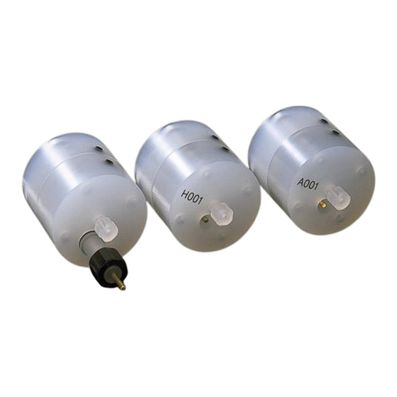
HyREF™ reference electrode is available. A third reference electrode is the in situ Ag/AgCl (ISAAC™). Fig. 1. The VT-03 electrochemical flow cell. The upper part, the inlet block, is separated from the working electrode block by means of a gasket (spacer, not shown). -
Page 5: Three-Electrode Configuration
5 years. Three-electrode configuration In the VT-03 flow cell a three-electrode configuration is used (Fig. 2). The working potential is set between the working electrode (WE) and the auxiliary electrode (AUX). -
Page 6: Working Electrode
VT03 flow cell user manual, ed. 8 If the working potential would be applied only over the REF versus the WE (without AUX), the working potential would be very well defined. However, the potential of a REF is only well defined if the current drawn is extremely low (pico-amperes) resulting in a very limited dynamic range. -
Page 7: Detection Limit
(OSA), pH=3.1 with KOH, 5% methanol sample 1.0 µmol/l norepinephrine, 20 µl injection temperature flow cell VT-03 flow cell with 3 mm GC WE mounted with 50 µm spacer E cell 800 mV (vs. Ag/AgCl, filled with saturated KCl) ca. 3 nA cell... - Page 8 In Fig. 3 a typical S/N ratio of a VT-03 glassy carbon flow cell with 2.74 mm WE is shown. In this example the concentration detection limit for norepinephrine based on three times the sigma-noise is 11 pmol/l (see Table II for conditions).
-
Page 9: Working Electrode Diameter
(S) as S -2/3 = k b where b is the spacer thickness and k a constant. Also for the VT-03 -2/3 flow cell the relation between S and b... - Page 10 VT03 flow cell user manual, ed. 8 Fig. 4. The signal and noise for 1.0 µmol/l nor-epinephrine measured at variable spacer thickness (given in µm). See Table II for other conditions. S (nA) 0.02 0.04 0.06 0.08 0.10 0.12 b^(-2/3) Fig.
- Page 11 CHAPTER 1 The electrochemical flow cell Table IV. Flow cell volume WE diameter (mm) 3.00 2.74 2.54 2.00 1.90 1.00 0.75 0.50 spacer (µm) cell volume (µl) 0.18 0.15 0.13 0.08 0.07 0.020 0.011 0.005 0.35 0.29 0.25 0.16 0.14 0.039 0.022 0.010...
-
Page 12: Reference Electrodes
VT03 flow cell user manual, ed. 8 C H A P T E R Reference electrodes The VT-03 flow cell is available with an ISAAC (in situ Ag/AgCl) reference electrode, a salt bridge Ag/AgCl reference electrode and a HyREF reference electrode. - Page 13 CHAPTER 2 Reference electrodes Fig. 6. Dependence of the Ag/AgCl REF potential on the chloride concentration. Table V. Potential of the Ag/AgCl reference electrode, dE is the potential difference with E in saturated KCl. Ag/AgCl (mmol/l) E Ag/AgCl (mV) dE (mV) 3500 2500 1500...
-
Page 14: Salt Bridge Ag/Agcl Reference Electrode
KCl. This REF for the VT-03 flow cell is factory filled with KCl. For certain applications another chloride salt is to be preferred. In case of perchlorate containing mobile phases, sodium chloride is mandatory, because potassium perchlorate precipitates and will clog the cotton wool frit. - Page 15 CHAPTER 2 Reference electrodes advisable first to construct a hydrodynamic (or scanning) voltammogram when using the HyREF. In Table VI the potential of the HyREF is measured against the Ag/AgCl (in sat'd KCl) electrode at different pH values. Table VI. Measured cell potential (HyREF - Ag/AgCl) versus pH. (mV) HyREF - Ag/AgCl 11.8...
-
Page 16: Installation
C H A P T E R Installation VT-03 flow cell with HyREF or ISAAC The flow cell is assembled properly when it arrives. The force on the bolts is pre-set to 13 Ncm (“a little bit beyond fingertight”). Familiarise yourself with this force, since over-tightening of the bolts strongly deteriorates the S/N ratio and eventually the cell itself. - Page 17 CHAPTER 3 Installation The ISAAC reference electrode requires 2 mmole/l chloride ions (KCl or NaCL) in the mobile phase. Add and equilibrate before installation of the ISAAC. See manual electrochemical detector for optimisation of working potential 1. Connect the column outlet to the flow cell inlet, using small-bore PEEK tubing (0.3 mm ID) and one of the fingertights supplied.
-
Page 18: Vt-03 Flow Cell With Salt Bridge Ref
LC-EC trace analyses. VT-03 flow cell with salt bridge REF The flow cell is assembled properly when it arrives. The force on the bolts is pre-set to 13 Ncm (“a little bit beyond fingertight”). Familiarise yourself with this force, since over-tightening of the bolts strongly deteriorates the S/N ratio and eventually the cell itself. - Page 19 CHAPTER 3 Installation Use proper eye and skin protection when working with solvents. 1. Check the REF visually for air bubbles and saturation with KCl. Some KCl crystals should be visible. When no crystals are visible or air bubbles are trapped the REF needs maintenance (see page 29). To prevent drying-out the REF is sealed with a cap on arrival.
- Page 20 VT03 flow cell user manual, ed. 8 within such a controlled environment is the minimum requirement for high- quality LC-EC trace analyses. Never switch ON the flow cell when: - the cell cable is not correctly connected - the cell is only partly (or not at all) filled with buffer - the outside of the flow cell is wet, particularly the part between the auxiliary and working electrode connection because substantial damage to the working electrode or electronics...
-
Page 21: Micro Flow Cell
This ensures the best performance. Assembling the micro flow cell The VT-03 micro flow cell has an 0.7 mm WE and is equipped with a 25 µm spacer. Older models of the VT-03 micro are equipped with a metal centring ring. - Page 22 VT03 flow cell user manual, ed. 8 1. Hold the WE block in horizontal position with the WE facing downwards and insert the 4 bolds in the 4 mounting holes of the WE block. Place the glass mounting plate on top of it, turn the glass plate with WE block up side down and place it on a flat surface/table.
- Page 23 CHAPTER 3 Installation touching the surface of the inlet block with the bold ends (this will minimize the change of scratching the inlet block surface). Then turn the inlet block downwards in horizontal position. The inlet block will now lay on top of the WE block with the bolds positioned on the mounting holes.
-
Page 24: Capillary Connections
VT03 flow cell user manual, ed. 8 Fig. 18. Fixing the two cell blocks with the hex key (tighten the bolds in a crosswise pattern). Capillary connections The micro flow cell is supplied with a low dead-volume fused silica capillary connection for coupling with capillary columns (< 1 mm ID fused silica columns) as a standard. - Page 25 CHAPTER 3 Installation Fig. 19. Mounting of the fused silica connector in the VT-03 micro flow cell. The capillary connector is not necessary with a 1 mm (or larger ID) column. In that case use narrow bore PEEK tubing ( 100 µm ID), and install as described on page 16 (ISAAC REF) or on page 18 (salt bridge REF).
- Page 26 VT03 flow cell user manual, ed. 8 8. Carefully push the block on the glass plate until the silica capillary is flush with the surface. 9. Fix the fused silica capillary firmly with the fingertight while keeping a slight pressure of the block on the glass plate. 10.
- Page 27 CHAPTER 3 Installation Fig. 21. Filling a VT-03 micro flow cell at 200 – 400 µL/min using a low dead- volume connector (1). Pressure must not rise > 200 bar. Read column instructions first. The flow cell is then filled at a higher flow rate.
-
Page 28: Maintenance
VT03 flow cell user manual, ed. 8 C H A P T E R Maintenance HyREF The HyREF reference electrode is in principle maintenance free. If not in use it should be stored dry after disassembling the flow cell. ISAAC The ISAAC reference electrode requires maintenance, usually not more than once in 3 months. -
Page 29: Ag/Agcl Salt Bridge
CHAPTER 4 Maintenance 2. Rinse the polishing disc with demi water before applying the diamond slurry! 3. Apply a few drops of slurry on the wetted polishing disc, and polish the electrode with a ‘figure 8’ motion for about one minute. Apply only gentle pressure. -
Page 30: Material
VT03 flow cell user manual, ed. 8 Check your REF regularly. If you do not see chloride salt crystals or if you see air bubbles, your REF needs maintenance. Material 1. An over-saturated and thoroughly degassed KCl solution. 2. A stainless steel rod of about 5 cm length and a diameter of 1 mm (e.g. a 1 mm drill). -
Page 31: Maintenance Of The Cotton Wool Frit
CHAPTER 4 Maintenance 11. Fig. 23, arrow) has a non-metallic appearance by gently grinding it on sanding paper; also the AgCl can be gently resurfaced in this way. 12. The frit in the salt bridge ensures electrical contact with the buffer. If the frit is discoloured or dried out, it has to be renewed. -
Page 32: Working Electrode
VT03 flow cell user manual, ed. 8 5. Use the drill to pack the wool from above through the KCl solution into the channel of the salt bridge, compress it firmly, but not too much, since electrical conduction is essential. 6. -
Page 33: Polishing
CHAPTER 4 Maintenance 3. Polishing the electrode surface Polishing 1. Shake diamond slurry thoroughly before use!! 2. Rinse the polishing disc with demi water before applying the diamond slurry! 3. Apply a small amount, a few drops is sufficient, of slurry on the wetted polishing disc, and polish the electrode with a ‘figure 8’... -
Page 34: Index
VT03 flow cell user manual, ed. 8 C H A P T E R Index... - Page 35 CHAPTER 5 Index Ag/AgCl reference electrode parts, 29 standard electrode potential, 12 auxiliary electrode, 5 detection limit, 7 flow cell volume, 11 HyREF installation, 16 reference electrode potential, 14 I/E converter, 5 installation micro flow cell, 21 installation flow cell, 16 ISAAC installation, 16 reference electrode potential, 12...
Need help?
Do you have a question about the VT-03 and is the answer not in the manual?
Questions and answers