Table of Contents
Advertisement
Advertisement
Table of Contents

Related Manuals for Masibus DDU-44

Summary of Contents for Masibus DDU-44
- Page 1 User’s Manual DDU-44/46 DDU-TM-44/46 Digital Display Unit Masibus Automation And Instrumentation Pvt. Ltd. B/30, GIDC Electronics Estate, Sector-25, Gandhinagar-382044, Gujarat, India +91 79 23287275-79 +91 79 23287281-82 Email: support@masibus.com Web: www.masibus.com...
-
Page 2: Table Of Contents
2.3 Time Signal Output ..................8 3. FRONT PICTURE ............................ 9 3.1 DDU-44/DDU-TM-44 IP20 Front views: .............. 9 3.2 DDU-44/DDU-TM-44 IP20 (SS Front Plate) Front views: ........10 3.3 DDU-46/DDU-TM-46 IP20 Front views: ............11 3.4 DDU-46/DDU-TM-46 IP20 (SS Front Plate) Front views: ........12 4. - Page 3 Model: DDU-TM-44/46 or DDU-44/46 Doc. Ref. no. : - m06c/om/101 Issue no. 04 7.1 Operation as Time/Date Display [DDU-TM-44/46 or DDU-44/46] ......29 8. COMMUNICATION GUIDELINES ..................... 31 8.1 Serial Time Frame Input ................31 8.2 Wireless Time Frame Input ................32 8.3 Wireless Configuration Frame Input ..............
-
Page 4: List Of Tables
Figure 16 Mounting detail for 4” 6 Digits [705mm x 215mm x 79mm] Enclosure (Flush Mount)..... 18 Figure 17 Connection on Terminal plate of DDU-TM-44/46 or DDU-44/46 Wall Mount ........19 Figure 18 Connection on Terminal plate of DDU-TM-44/46 or DDU-44/46 Panel Mount ....... 19 Figure 19 RS232 Connection Details ...................... -
Page 5: Introduction
Every effort has been made to ensure accuracy in the preparation of this manual. Should any errors or omissions come to your attention, however, please inform MASIBUS Sales office or sales representative. Under no circumstances may the contents of this manual, in part or in whole, be transcribed or copied without our permission. -
Page 6: Product Ordering Code
Model: DDU-TM-44/46 or DDU-44/46 Doc. Ref. no. : - m06c/om/101 Issue no. 04 Product Ordering Code Table 2 Product Ordering Code for DDU-TM-44/46 or DDU-44/46 Ordering Code Display Model No Of Digits Mounting Input Type1 Input Type2 Size DDU / DDU-TM 4”... -
Page 7: Specifications
3.0Kg(SS Front) 4.1Kg (SS Front) Material Mild Steel/SS(SS-304 Only Front Plate) Mounting Wall Mount/ Panel Mount/Flush Mount Note: DDU-44/46 is available with SS (SS-304) Front Plate without Conceal Box with Wall Mount Key Holes. User’s Manual Page 7 of 36... -
Page 8: Time Signal Input
Wireless Approx 300 meters Output (Depends on Site Conditions) Note: If DDU-44/46 or DDU-TM-44/46 is in sync using Serial [RS232/RS485] than do not use Serial [RS232/RS485] for Retransmission. Isolation (Withstanding voltage) Between primary terminals* and secondary terminals**: At least 1500 V AC for 1 minute ... -
Page 9: Front Picture
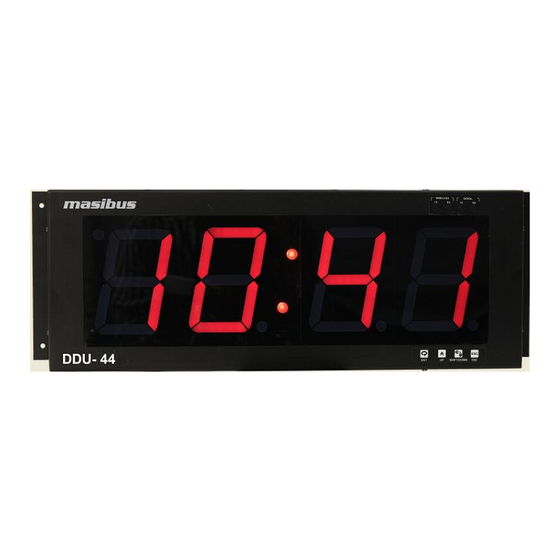
Model: DDU-TM-44/46 or DDU-44/46 Doc. Ref. no. : - m06c/om/101 Issue no. 04 3. FRONT PICTURE 3.1 DDU-44/DDU-TM-44 IP20 Front views: Figure 1 Front View of DDU-44 IP20 Figure 2 Front View of DDU-TM-44 IP20 User’s Manual Page 9 of 36... -
Page 10: Ddu-44/Ddu-Tm-44 Ip20 (Ss Front Plate) Front Views
Doc. Ref. no. : - m06c/om/101 Issue no. 04 3.2 DDU-44/DDU-TM-44 IP20 (SS Front Plate) Front views: Figure 3 Front View of DDU-44 IP20 (SS Front Plate) Figure 4 Front View of DDU-TM-44 IP20 (SS Front Plate) User’s Manual Page 10 of 36... -
Page 11: Ddu-46/Ddu-Tm-46 Ip20 Front Views
Model: DDU-TM-44/46 or DDU-44/46 Doc. Ref. no. : - m06c/om/101 Issue no. 04 3.3 DDU-46/DDU-TM-46 IP20 Front views: Figure 5 Front View of DDU-46 IP20 Figure 6 Front View of DDU-TM-46 IP20 User’s Manual Page 11 of 36... -
Page 12: Ddu-46/Ddu-Tm-46 Ip20 (Ss Front Plate) Front Views
Model: DDU-TM-44/46 or DDU-44/46 Doc. Ref. no. : - m06c/om/101 Issue no. 04 3.4 DDU-46/DDU-TM-46 IP20 (SS Front Plate) Front views: Figure 7 Front View of DDU-46 IP20 (SS Front Plate) Figure 8 Front View of DDU-TM-46 IP20 (SS Front Plate) User’s Manual... -
Page 13: Installation & Mounting Detail
It may cause accidents. 4.2 Wall Mount For DDU-TM-44/DDU-44 Wall mounting, there are two mounting clamp as shown in below drawing. Figure 9 Mounting detail for 4” 4 Digits [460mm x 175mm x 70mm] Enclosure (Wall Mount) User’s Manual... -
Page 14: Figure 10 Mounting Detail For 4" 4 Digits [500Mm X 215Mm X 79Mm] Enclosure (Wall Mount, Ss Front)
Issue no. 04 For DDU-TM-44/DDU-44 with SS Front Plate Wall mounting, there are two mounting Key hole in Bottom Part of Enclosure as shown in below drawing. Figure 10 Mounting detail for 4” 4 Digits [500mm x 215mm x 79mm] Enclosure (Wall Mount, SS Front) ... -
Page 15: Figure 12 Mounting Detail For 4" 6 Digits [705Mm X 215Mm X 79Mm] Enclosure (Wall Mount, Ss Front)
Model: DDU-TM-44/46 or DDU-44/46 Doc. Ref. no. : - m06c/om/101 Issue no. 04 For DDU-TM-46/DDU-46 with SS Front Plate Wall mounting, there are two mounting Key hole in Bottom Part of Enclosure as shown in below drawing. Figure 12 Mounting detail for 4” 6 Digits [705mm x 215mm x 79mm] Enclosure (Wall Mount, SS Front) User’s Manual... -
Page 16: Panel Mount
Issue no. 04 4.3 Panel Mount For DDU-TM-44/DDU-44 Panel mount two clamps are used for panel mounting as shown in below image Figure 13 Mounting detail for 4” 4 Digits [460mm x 175mm x 70mm] Enclosure (Panel Mount) ... -
Page 17: Flush Mount
2. DDU-TM-44/DDU-44 Instrument without Conceal Box 3. SS- Front Plate 4. Instrument mounting Self Thread screws 4 Nos.(Length 30mm) Enclosure Dimension of DDU-TM-44/DDU-44 with SS Front Plate: 500mm (W) X 215mm (H) X 79mm (D) User’s Manual Page 17 of 36... -
Page 18: Figure 16 Mounting Detail For 4" 6 Digits [705Mm X 215Mm X 79Mm] Enclosure (Flush Mount)
Model: DDU-TM-44/46 or DDU-44/46 Doc. Ref. no. : - m06c/om/101 Issue no. 04 For DDU-TM-46/DDU-46 with SS Front Plate Flush mounting, there are Six mounting hole in SS Front Plate as shown in below drawing. Figure 16 Mounting detail for 4” 6 Digits [705mm x 215mm x 79mm] Enclosure (Flush Mount) 1. -
Page 19: Terminal Connections
5. TERMINAL CONNECTIONS 5.1 Terminal connections on DDU-TM-44/46 or DDU-44/46 Enclosures 5.1.1 Terminal connection for Wall Mount Enclosure Figure 17 Connection on Terminal plate of DDU-TM-44/46 or DDU-44/46 Wall Mount Table 3 Terminal Connection Detail of Enclosures (Wall Mount) Terminal Type... -
Page 20: How To Connect Wires
Supply voltage must be below maximum voltage rating specified on the label. Figure 19 RS232 Connection Details Figure 20 RS485 Connection Details Note: - Consider RS485 Connection Detail for DDU-TM-44/DDU-44 or DDU-TM-46/DDU-46 same as above figure 15 In case of RS-232 Output base master unit, external RS-232 to RS-485 Connector required, and it will be connected direct in case of RS-485 output from Master. -
Page 21: Configuration Guidelines
User can set blinking of Date DP and Time Display Colon in unlock condition. 6.2.1 Run Mode As Shown in Fig 8 DDU-TM-44/46 or DDU-44/46, will display Time or Date as per set parameter in Run mode. 6.2.2 Password Mode (PSWD): ... -
Page 22: Figure 21 Display And Key Configuration Detail
Model: DDU-TM-44/46 or DDU-44/46 Doc. Ref. no. : - m06c/om/101 Issue no. 04 Figure 21 Display and Key Configuration Detail User’s Manual Page 22 of 36... - Page 23 Model: DDU-TM-44/46 or DDU-44/46 Doc. Ref. no. : - m06c/om/101 Issue no. 04 User’s Manual Page 23 of 36...
- Page 24 Doc. Ref. no. : - m06c/om/101 Issue no. 04 Note: - Figure 21 Display the Key configuration of DDU-TM-44/DDU-44.In DDU-TM- 46/DDU-46 Key configuration same as DDU-TM-44/DDU-44 but only Change in date format configuration. The Date format given for Display ...
- Page 25 Model: DDU-TM-44/46 or DDU-44/46 Doc. Ref. no. : - m06c/om/101 Issue no. 04 6.2.3 Configuration Mode 6.2.3.1 Display Configuration Mode (DISP): Press Enter Key to Enter in Display mode, it will enter in View mode and shows Current Display Mode.
- Page 26 Auto mode is enabled when you are selecting no and ser in retransmission configuration. In Auto mode DDU-TM-44/46 or DDU-44/46 will scan RF channel between0 to 9 for Receiving RF Signals from Wireless master Time Signal provider. When unit receive RF Time Frame at that time Wireless Rx Led glow.
- Page 27 When it Receive RF or Time Frame at that time Wireless or Serial RX Led glow respectively. If DDU-TM-44/46 or DDU-44/46 is in sync using Serial [RS232/RS485] than do not use Serial [RS232/RS485] for Retransmission. 6.2.3.15 Slave ID configuration: ...
-
Page 28: Table 5 Error Message Display Code
Configuration command through Master (GPS-MC-2) Over Wireless: DDU-TM-44/46 or DDU-44/46 offers facility to the users for configuring communication parameters of serial port, Display Format Selection, Time Zone Selection, Manual Time Set, Set Default Parameter, Retransmission selection set by Key or configuration Frame Sent by master GPS-MC-2 over Wireless and View Current Settings by Key Configuration. -
Page 29: Operation Information
1. Insert the power cord into an appropriate connector inside the clock. 2. Upon Power up of DDU-TM-44/46 or DDU-44/46, The Unit display Slave id Then if unit is wireless input model then it display the RF receive channel and transmit channel that you are set. Then it will start displaying time/date from internal RTC otherwise it will start displaying time/date from internal RTC. - Page 30 7.1.6 Manual Time Settings In DDU-TM-44/46 or DDU-44/46, if there is no Time frame input available, at that time user can enter Manually Time and Date, Manual Time set can be done by using Key configuration as shown in section 6.2.
-
Page 31: Communication Guidelines
Model: DDU-TM-44/46 or DDU-44/46 Doc. Ref. no. : - m06c/om/101 Issue no. 04 8. COMMUNICATION GUIDELINES 8.1 Serial Time Frame Input 8.1.1 NMEA-0183[RMC] Format The $GPRMC sentence contains time and date of position fix, speed and course information. The following examples show the contents of a typical RMC sentence: The settings for this serial format is 9600, 8, N, 1. -
Page 32: Wireless Time Frame Input
8.2 Wireless Time Frame Input 8.2.1 Wireless Clock Network DDU-TM-44/46 or DDU-44/46 designed to create mesh network protocol to increase the range of DDU-TM-44/46 or DDU-44/46 network as shown in fig 22. As shown in fig 22, there is Wireless master connected with GPS, which transmit the GPS time code in 866 MHz frequency. -
Page 33: Wireless Configuration Frame Input
If you select Auto option then it will be configured as auto mode, in this mode, at every power on DDU-TM-44/46 or DDU-44/46 will first try to sync on last stored RF channel, it will try for 9 minutes to sync with last stored channel. -
Page 34: Troubleshooting Tips
5. If you are trying to sync DDU-TM-XX with Wireless mater , then check they are not out of range , both unit must be in range of 100 meter area , and if you are trying to sync DDU-TM-44/46 or DDU-44/46 with DDU-TM-44/46 or DDU-44/46 , slave to slave communication , then it must be in range of 50 meter area. - Page 35 4. If your Time Code source is providing Time Zone offsets these functions must be disabled in your DDU-TM-44/46 or DDU-44/46 in order to eliminate double offsets. If these troubleshooting tips do not solve your problem then, please contact Customer support at either nearest area office or Main Head Office as given on the first page.
-
Page 36: Revision History
Following Changes added in m06bom101-04 compared to m06bom101-03. 1) DDU-46 SS Wall Mount unit image added. 2) Power supply range updated in Specification. Masibus Automation & Instrumentation Pvt. Ltd. Customer Support Division B/30, GIDC Electronics Estate, Sector-25, Gandhinagar-382044, Gujarat, India...
Need help?
Do you have a question about the DDU-44 and is the answer not in the manual?
Questions and answers