Table of Contents
Advertisement
Quick Links
Advertisement
Table of Contents

Related Manuals for Masibus DDU-26

Summary of Contents for Masibus DDU-26
- Page 1 User’s Manual DDU-24/26 Digital Display Unit Masibus Automation And Instrumentation Pvt. Ltd. B/30, GIDC Electronics Estate, Sector-25, Gandhinagar-382044, Gujarat, India +91 79 23287275-79 +91 79 23287281-82 Email: support@masibus.com Web: www.masibus.com...
-
Page 2: Table Of Contents
2.3 Time Signal Output ..................8 3. FRONT PICTURE ..........................9 3.1 DDU-24 IP20 Front views: ................9 3.2 DDU-26 IP20 Front views: ................9 3.2 DDU-24-XP Front views: ................10 3.3 DDU-26-XP Front views: ................10 4. INSTALLATION& MOUNTING DETAIL ..................11 4.1 Safety Precautions in Installation .............. - Page 3 Model: DDU-24/26 Doc. Ref. no. : - m06bom101 Issue no. 09 8. COMMUNICATION GUIDELINES ....................43 8.1 Serial Time Frame Input ................43 8.2 Wireless Time Frame Input ................44 8.3 Wireless Configuration Frame Input ..............45 8.4 NTP Packet format: ..................46 8.5 Serial Time Frame Output ................
-
Page 4: List Of Tables
Figure 7 Mounting detail for [350 mm x 180 mm x 85 mm] Enclosure of DDU-24-XP ......12 Figure 8 Mounting detail for [455 mm x 180 mm x 85 mm] Enclosure of DDU-26-XP ......13 Figure 9 Conceal Box Fitting details ......................14 Figure 10 Main Box Fitting in Conceal Box details .................. -
Page 5: Introduction
Every effort has been made to ensure accuracy in the preparation of this manual. Should any errors or omissions come to your attention, however, please inform MASIBUS Sales office or sales representative. Under no circumstances may the contents of this manual, in part or in whole, be transcribed or copied without our permission. -
Page 6: Product Ordering Code
Accessories Conceal Box for Flush Mounting [Brick Wall]DDU-24/26 DDU-24 [280(W)*100(H)*47(D)mm] DDU-26 [381(W)*100(H)*47(D)mm] Safety Precautions The product and the instruction manual describe important information to prevent possible harm to users and damage to the property and to use the product safely. -
Page 7: Specifications
Model: DDU-24/26 Doc. Ref. no. : - m06bom101 Issue no. 09 2. SPECIFICATIONS 2.1 Technical Specification Sheet Specifications DDU-24 DDU-26 Display No of Digit Four 2.3”(57mm) Digit Height Type of display Display Color Time: HH:MM TIME:HH:MM:SS Display Format Date: DD:MM / MM:DD DATE:DD:MM:YY/MM:DD:YY/YY:MM:DD ... -
Page 8: Time Signal Input
180mm X 350mm X 85mm ( for DDU-24) 3/4” ET-4 Nos Size [ H x W x D] [in mm] Cable entry size/no 180mm X 455mm X 85mm ( for DDU-26) 1 Blind Plug & 1 DC Cable gland Area Classification Zone 1&2 Plug Details 3/4‟‟ET... -
Page 9: Front Picture
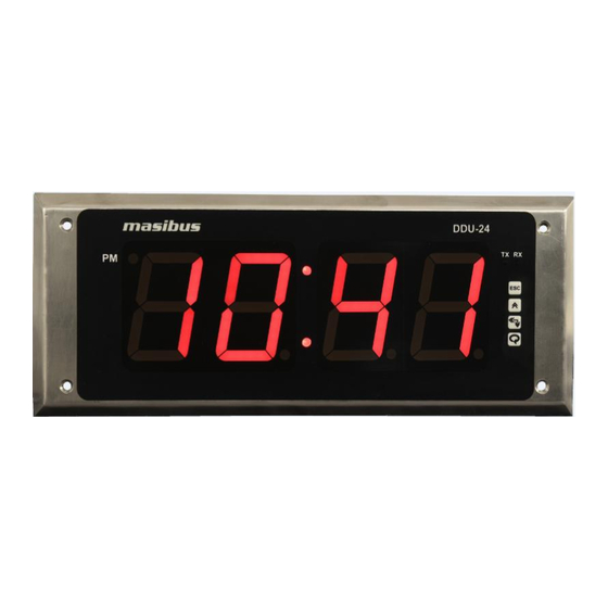
Doc. Ref. no. : - m06bom101 Issue no. 09 3. FRONT PICTURE 3.1 DDU-24 IP20 Front views: Figure 1 Front View of DDU-24 3.2 DDU-26 IP20 Front views: Figure 2 Front View of DDU-26 User’s Manual Page 9 of 51... -
Page 10: Ddu-24-Xp Front Views
Model: DDU-24/26 Doc. Ref. no. : - m06bom101 Issue no. 09 3.2 DDU-24-XP Front views: Figure 3 Front View of DDU-24-XP 3.3 DDU-26-XP Front views: Figure 4 Front View of DDU-26-XP User’s Manual Page 10 of 51... -
Page 11: Installation& Mounting Detail
Model: DDU-24/26 Doc. Ref. no. : - m06bom101 Issue no. 09 4. INSTALLATION& MOUNTING DETAIL 4.1 Safety Precautions in Installation 1. To minimize the possibility of fire or shock hazards, do not expose this instrument to rain or excessive moisture. 2. -
Page 12: Figure 6 Mounting Detail For [404Mm X 118Mm X 47Mm] Enclosure Of Ddu-26
Doc. Ref. no. : - m06bom101 Issue no. 09 For Wall mounting of DDU-26, there are two mounting key slot as shown in below drawing in Back side of Main Box Figure 6 Mounting detail for [404mm x 118mm x 47mm] Enclosure of DDU-26 ... -
Page 13: Figure 8 Mounting Detail For [455 Mm X 180 Mm X 85 Mm] Enclosure Of Ddu-26-Xp
Doc. Ref. no. : - m06bom101 Issue no. 09 For Wall mounting of DDU-26-XP, there are Four mounting hole as shown in below drawing of Enclosure Figure 8 Mounting detail for [455 mm x 180 mm x 85 mm] Enclosure of DDU-26-XP User’s Manual... -
Page 14: Brick Wall Flush Mount
After Fitting Conceal box, fit DDU-24/26 assembled instrument as shown in Fig 6 using 4 SS M3 X 25 mm screws. Figure 9 Conceal Box Fitting details Conceal Box Dimension for DDU-24:280mm X 100mm X 47mm Conceal Box Dimension for DDU-26:381mm X 100mm X 47mm User’s Manual Page 14 of 51... -
Page 15: Figure 10 Main Box Fitting In Conceal Box Details
5. DDU-24/26 Instrument 6. SS- Front Plate 7. Instrument mounting screws Enclosure Dimension of DDU-24 with Conceal Box (1+5+6):298mm X 118mm X 54mm Enclosure Dimension of DDU-26 with Conceal Box (1+5+6):404mm X 118mm X 54mm User’s Manual Page 15 of 51... -
Page 16: Terminal Connections
5.1.1 Terminal connection for Wall/Brick Wall Mount Enclosure Figure 11 Connection on Terminal plate of DDU-24 Wall / Brick Wall Mount Figure 12 Connection on Terminal plate of DDU-26 Wall / Brick Wall Mount Figure 13 Connections on Base Plate of DDU-24-XP/DDU-26-XP User’s Manual... -
Page 17: Figure 14 Connection On Terminal Plate Of Ddu-24 (Ntp + Poe) Wall / Brick Wall Mount
Figure 14 Connection on Terminal plate of DDU-24 (NTP + PoE) Wall / Brick Wall Mount Figure 15 Connection on Terminal plate of DDU-26 (NTP + PoE) Wall / Brick Wall Mount Figure 16 Connection on Terminal plate of DDU-24 (NTP) Wall / Brick Wall Mount User’s Manual... -
Page 18: How To Connect Wires
Model: DDU-24/26 Doc. Ref. no. : - m06bom101 Issue no. 09 Figure 17 Connection on Terminal plate of DDU-26 (NTP) Wall / Brick Wall Mount 5.1.2 Terminal connection detail for DDU-24/26 Enclosure Table 3 Terminal Connection Detail of Enclosures Terminal Type... -
Page 19: Figure 18 Rs232 Connection Details
Model: DDU-24/26 Doc. Ref. no. : - m06bom101 Issue no. 09 Unused terminals should not be used as jumper points as they may be internally connected, which may cause damage to the unit. Use >250V-1Amp Cable for Power Supply. ... -
Page 20: Figure 21 Open Screw Terminal Of Ddu-24-Xp
7. After successful configuration close the front cover using Allen key and mount it on the wall. Figure 21 Open Screw Terminal of DDU-24-XP Figure 22 connection of DDU-24-XP Note: The installation Process of DDU-26-XP is same as DDU-24-XP. User’s Manual Page 20 of 51... -
Page 21: Configuration Guidelines
Action of CONFIG can be switched during clock operation. No power on/off cycle is required to change these modes. 2. Default Setting of DDU-26 Same as above configuration but only change in Date Format. In DDU-26 date Format is DD.MM.YY by Default. - Page 22 Model: DDU-24/26 Doc. Ref. no. : - m06bom101 Issue no. 09 The communication parameters include baud rate, number of stop bits and parity. User Can Set Manual Time if no availability of Time Inputs. The user is free to choose Time Display, Date Display and Both in Alternate Time/Date Display. ...
-
Page 23: Figure 23 Display And Key Configuration Details
Model: DDU-24/26 Doc. Ref. no. : - m06bom101 Issue no. 09 6.2.3.5 Manual Date Set Configuration (S-DT): Press Enter Key to Enter in Manual Date Set mode, it will enter in View mode and shows Current Date on Display. ... - Page 24 Model: DDU-24/26 Doc. Ref. no. : - m06bom101 Issue no. 09 User’s Manual Page 24 of 51...
- Page 25 DDU-24 but only Change in date format configuration. The Date format given for Display For DDU-24: 1. DD/MM 2. MM/DD For DDU-26 1. DD/MM/YY 2. MM/DD/YY 3. YY/MM/DD Wireless Input model: First power on unit it will display Slave ID and RF receive channel 0 then it will start to display Time in default condition that are set in unit.
-
Page 26: Model: Ddu
Model: DDU-24/26 Doc. Ref. no. : - m06bom101 Issue no. 09 6.2.3.6Time Zone Configuration (OFST): Press Enter Key to Enter in Time Zone offset mode, it will enter in View mode and shows Current Time Zone offset on Display. ... - Page 27 Model: DDU-24/26 Doc. Ref. no. : - m06bom101 Issue no. 09 Press Enter in View mode to enter in Edit mode, in Edit mode Set RF Transmit Channel using INC Key, Press Enter key to set the RF Receive Channel. ...
- Page 28 : Disable Note:- 1. Default Setting of DDU-26 Same as above configuration but only change in Date Format. In DDU-26 date Format is DD.MM.YY by Default. 2. Default Setting of DDU-24/26 with NTP or NTP +PoE Same as above configuration but only change in Display Unlock Blink and Retransmission.
- Page 29 6.2.4.1 For the First Time setup follow the below procedure. 1. Masibus DDU-24/26 Display Unit has default network settings as mentioned in Section 6.1, First connect the Display Unit direct with local computer using a cross cable. (Not in Network) 2.
- Page 30 Doc. Ref. no. : - m06bom101 Issue no. 09 5. Enter Login–name and press enter. Enter password and press enter. Login–name and password both are case sensitive. Default Login– name and password both are “masibus”. 6. IP : This command is used to change IP address of DDU-24/26.
- Page 31 Model: DDU-24/26 Doc. Ref. no. : - m06bom101 Issue no. 09 8. GTY This command is used to change Gateway of DDU-24/26. Gateway should be entered in xxx.xxx.xxx.xxx form. Enter new Gateway and press enter. To save the new Gateway. Press „Y‟ else press „N‟. If you press Y new Gateway will be saved and if you press N the previous Gateway will be retained ...
- Page 32 Model: DDU-24/26 Doc. Ref. no. : - m06bom101 Issue no. 09 10. SIP2 This command is used to change IP address of NTP time source (NTP Secondary Server) for DDU-24/26. IP address should be entered in xxx.xxx.xxx.xxx form. ...
- Page 33 Model: DDU-24/26 Doc. Ref. no. : - m06bom101 Issue no. 09 12. NQT This command is used to change NTP Query Request Time Out Time forDDU-24/26. NTP Query Request Time Out Time should be entered between 1 to 60. ...
- Page 34 Model: DDU-24/26 Doc. Ref. no. : - m06bom101 Issue no. 09 14. NOT This command is used to change NTP Number of time out counts before switching servers forDDU-24/26. Number of time out counts before switching servers me should be entered between1 to 15. ...
- Page 35 Model: DDU-24/26 Doc. Ref. no. : - m06bom101 Issue no. 09 1. Z This command is used to Set Time Zone Offset Configuration for DDU-24/26. By entering “Z” You will enter in Time Zone Offset Configuration. 16.1“Z” ”1” Command: ...
- Page 36 This command is used to Set Manual Time Setting for DDU-24/26. By entering “MT” You will enter in Manual Time Setting Configuration. Enter Time and Date in HH:MM,DD/MM/YY mode for DDU-24 and HH:MM:SS,DD/MM/YY for DDU-26 after it will give conformation. 3. P ...
- Page 37 „N‟. If you press Y new Login name will be saved and if you press N the previous Login name will be retained. The default Login name is „masibus‟. Remember that the Login name should not exceed 10 characters. If you try to keep a Login name that has more than 10 characters, the system will show an error “Invalid Entry”...
- Page 38 Model: DDU-24/26 Doc. Ref. no. : - m06bom101 Issue no. 09 6. ETH0 [ETH(Zero)] This command is used to see present NTP configurations. 7. Q This command is used to close Telnet session. 6.4.3.3 Important Points for Telnet Configuration Digital Display Unit‟s Telnet Server has timeout period of 5 minutes.
-
Page 39: Table 4 Error Message Display Code
Model: DDU-24/26 Doc. Ref. no. : - m06bom101 Issue no. 09 6.2.5 Configuration command through Master (GPS-MC-2) Over Wireless: DDU-24/26 offers facility to the users for configuring communication parameters of serial port, Display Format Selection, Time Zone Selection, Manual Time Set, Set Default Parameter, Retransmission selection set by Key or configuration Frame Sent by master GPS-MC-2 over Wireless and View Current Settings by Key Configuration. -
Page 40: Operation Information
Model: DDU-24/26 Doc. Ref. no. : - m06bom101 Issue no. 09 7. OPERATION INFORMATION 7.1 Operation as Time/Date Display [DDU-24/26] 1. Insert the power cord into an appropriate connector inside the clock. 2. Upon Power up of DDU-24/26, The Unit display Slave id Then if unit is wireless input model then it display the RF receive channel and transmit channel that you are set. - Page 41 If the clock is unable to achieve a time code lock see the section entitled Troubleshooting Tips. 10. For Serial Communication time codes date must be encoded to the standard specification. These specifications are also supported by Masibus Master Clock systems [see Communication Guidelines Section 8.2].
- Page 42 Model: DDU-24/26 Doc. Ref. no. : - m06bom101 Issue no. 09 For DDU-26: 1. DD/MM/YY 2. MM/DD/YY 3. YY/MM/DD In DDU-24/26, there is one option of setting Time for enable or disable the blinking of Colon and DP in unlocking condition.
-
Page 43: Communication Guidelines
Model: DDU-24/26 Doc. Ref. no. : - m06bom101 Issue no. 09 8. COMMUNICATION GUIDELINES 8.1 Serial Time Frame Input 8.1.1 NMEA-0183[RMC] Format The $GPRMC sentence contains time and date of position fix, speed and course information. The following examples show the contents of a typical RMC sentence: The settings for this serial format is 9600, 8, N, 1. -
Page 44: Wireless Time Frame Input
Model: DDU-24/26 Doc. Ref. no. : - m06bom101 Issue no. 09 8.1.2 T-Format The settings for this format are programmable. The full data message of T-format shall consist of 21 printable characters with a concluding CRLF as follows: Table 7 T-Format Description Number of Character... -
Page 45: Wireless Configuration Frame Input
Doc. Ref. no. : - m06bom101 Issue no. 09 Figure 24 Wireless Network of DDU-24/26 Note: - Wireless network of DDU-26 is same as DDU-24. 8.2.3 DDU-24/26 Receive Option Details In DDU-24/26 you can set RF – receive channel between 0 – 9 and auto option. -
Page 46: Ntp Packet Format
Model: DDU-24/26 Doc. Ref. no. : - m06bom101 Issue no. 09 8.4 NTP Packet format: Figure 25 NTP packet header format Following is the description of each parameter in NTP Packet: Leap 2-bit integer warning of an impending leap second to be inserted or Deleted in the last minute of the current month, coded as follows: 0 no warning 1 last minute of the day has 61 seconds... -
Page 47: Serial Time Frame Output
Model: DDU-24/26 Doc. Ref. no. : - m06bom101 Issue no. 09 Figure 26 NTP Timestamp Format Follow www.ntp.org for more details for NTP Time Format and Client Settings. 8.5 Serial Time Frame Output DDU-24-FLP Transmit only NMEA-0183[RMC] Format same as Input of NMEA-0183[RMC] Describe in section 8.1.1. -
Page 48: Troubleshooting Tips
Model: DDU-24/26 Doc. Ref. no. : - m06bom101 Issue no. 09 9. TROUBLESHOOTING TIPS If the operating display does not appear after turning on the controller‟s power, follow the measures in the procedure below. If a problem appears complicated, contact our Customer support representative. IMPORTANT Take note of the parameter settings when asking the vendor for repair. - Page 49 Model: DDU-24/26 Doc. Ref. no. : - m06bom101 Issue no. 09 PROBLEM: UTC time and/or date is incorrect. There are several potential failure points: • Invalid, intermittent or missing Time Code source • Date/year overwrite function for non‐date encoded Time Code may be configured improperly •...
- Page 50 Model: DDU-24/26 Doc. Ref. no. : - m06bom101 Issue no. 09 1. Verify that the NTP server(s) specified are reachable, communicating, and are not flagging their reported time as invalid. 2. Verify that a gateway/router/firewall has been configured that allows the clock to communicate outside of its local network.
-
Page 51: Revision History
Doc. Ref. no. : - m06bom101 Issue no. 09 REVISION HISTORY Following Changes added in m06bom101-09 compared to m06bom101-08. 1) DDU-24 and DDU-26 sticker added for NTP Option. 2) DDU-26-XP Description Detail added. Masibus Automation & Instrumentation Pvt. Ltd. Customer Support Division...
Need help?
Do you have a question about the DDU-26 and is the answer not in the manual?
Questions and answers