Wulfsberg P-2000 Operator's Manual
Transceiver systems
Hide thumbs
Also See for P-2000:
- Installation manual (41 pages) ,
- Operator's manual (40 pages) ,
- Installation manual (81 pages)
Table of Contents
Advertisement
Quick Links
Advertisement
Table of Contents

Related Manuals for Wulfsberg P-2000


Summary of Contents for Wulfsberg P-2000
- Page 1 Operator’s Manual P-2000 and C-2000/RT-2000 Transceiver Systems P-2000 Part Number: 400-049200-11-xxx-xxxx-xxxx Software Mod: 1 C-2000 Part Number 400-049300-11-xxx-xxxx-xxxx Software Mod: 1 RT-2000 Part Number 400-049400-11-xxx-xxxx-xxxx Software Mod: 1...
-
Page 2: Table Of Contents
Wulfsberg Electronics P-2000 and C-2000/RT-2000 Operator’s Manual TABLE OF CONTENTS INTRODUCTION ...............................3 ..................................3 EATURES ............................4 RANSCEIVER VERVIEW BASIC OPERATIONS..............................5 & C ............................5 RONT ANEL ONTROLS ..............................6 EYPAD UTTONS ................................7 .........................10 ETTING THE ISPLAY RIGHTNESS ..........................10 ETTING THE OLUME EVEL ........................11... -
Page 3: Introduction
(806-870 MHz). For applications where multiple points of user operation are required, one or more C-2000's can be added. For purposes of this manual the term "P-2000" shall be used to describe a P-2000 or C-2000/RT-2000 installation. The features and user interface are identical in both systems. -
Page 4: Transceiver Overview
28VDC, 5 VDC or 5 VRMS AC. The Wulfsberg C-2000 is a control display unit that can be used as a slave control head with a P-2000 panel mount transceiver, or as either a primary or slave control head for the RT- 2000 remote transceiver. Versions of the C-2000 include black faceplate and options for either Standard or NVG compatible displays. -
Page 5: Basic Operations
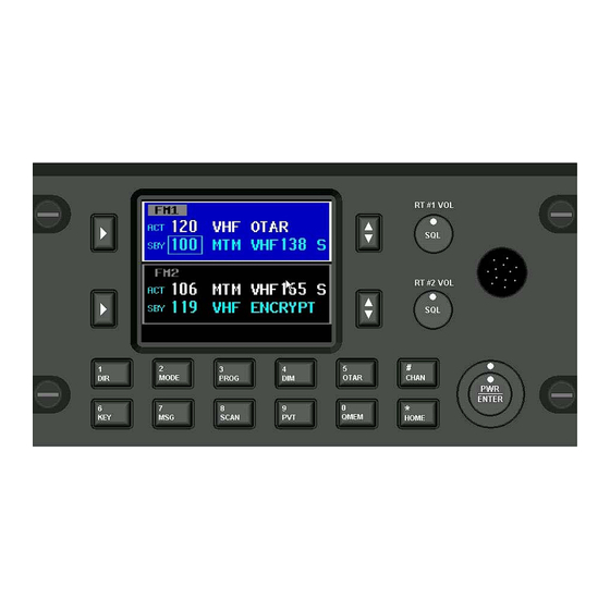
Button DISPLAY The P-2000 has a color LCD display. It provides the visual feedback for the system. Exactly what is displayed depends on the current operating mode of the P-2000. During normal operation, the top area shows information for FM #1 and the bottom line shows information for FM #2. -
Page 6: Keypad Buttons
Wulfsberg Electronics P-2000 and C-2000/RT-2000 Operator’s Manual Keypad Buttons The P-2000 has a 12 button keypad. Each button’s functions are described below. 1:DIR Toggles the active transceiver in and out of 6:KEY This button will prompt the user for a DIRECT mode. -
Page 7: The Home Page
“VHF” or “MAIN”. ACT/SBY - The normal operating mode of the P-2000 is very similar to most ATC COMM radios. The user tunes the Standby channel and then “flip-flops” it into the Active channel position using the TRANSFER button. The radio is loaded with Active channel. - Page 8 Wulfsberg Electronics P-2000 and C-2000/RT-2000 Operator’s Manual Discreet Indicators – The following discreet indicators apply to both FM1 and FM2. FM 1 Discreet Indicators ACTIVE Channel Channel Alpha Identifier STANDBY Channel This helps the user know the information in this block is for the transceiver located in FM #1 Position.
- Page 9 When initialization is complete, the HOME PAGE will appear on the display. To power the P-2000 OFF, press and hold the PWR button for 3 seconds. The following message flashes on the display several times: Continue to hold the PWR button until the message stops flashing and the display turns off.
-
Page 10: Setting The Display Brightness
Setting the Volume Level When you first power on the P-2000, the volume levels for both transceivers will be reset to the level that was active when the unit was powered down. You can change the volume level as follows. -
Page 11: Selecting The Active Transceiver
FM #2 Select When the P-2000 operating in MODE 1 (only one headset shared between two transceivers), the active transceiver is the one that will be used for transmitting. In MODE 1, the transceivers (FM1 and FM2) will have their receive audio summed together and sent to the headset. -
Page 12: Selecting A Standby Channel Using The Cursor/Tune Knob
Selecting a Standby Channel Using the Cursor/Tune Knob When the P-2000 first powers on, the selected channels will be set to those that were active when the unit was powered down. To select a different preset channel, do the following: Using the Select Knob, put the square cursor around the channel number. -
Page 13: Selecting A Channel By Alphanumeric Identifier
Using the Direct/Repeat Feature The P-2000 supports both direct and repeat modes of operation. Any preset channel that has identical transmit and receive frequencies is considered a direct channel. If the transmit and receive frequencies are different, the P-2000 considers the channel a repeater channel. -
Page 14: Receiving/Transmitting
FM #1 transmitting. Receiving The P-2000 is constantly monitoring its radios for reception. When a signal is received, the P-2000 will light the receive indicator for the receiving radio, and route the audio to the operator’s headset (assuming the associated intercom switch is selected). -
Page 15: Qmem Operations
Wulfsberg Electronics P-2000 and C-2000/RT-2000 Operator’s Manual QMEM Operations When the user presses the QMEM key, the system will enter the QMEM mode. This mode allows the user to either select or program a QMEM location. When the user presses the QMEM key, then presses a keypad key (0-9), the channel programmed into the corresponding (0-9) QMEM location shall be loaded into the active channel, and the previously active channel shall be loaded into the standby channel. -
Page 16: Message Page
Wulfsberg Electronics P-2000 and C-2000/RT-2000 Operator’s Manual MESSAGE PAGE This page allows the user to manage text messages for the system. When no unread messages exist within the system, the MSG indicator will not be visible on the normal operation page. When the MSG key is pressed on the normal operation page and no messages are available, the no message page is displayed. - Page 17 Wulfsberg Electronics P-2000 and C-2000/RT-2000 Operator’s Manual The Select Knob allows the selection of the message list, back button, erase button, and next button. Pressing ENTER while the BACK button is selected returns to the previous page. Pressing ENTER while the ERASE button is selected deletes the currently selected message from the message list.
-
Page 18: Programming/Editing A Preset Channel
Wulfsberg Electronics P-2000 and C-2000/RT-2000 Operator’s Manual Programming/Editing a Preset Channel The EDIT PAGE allows the operator to temporarily change properties of a preset channel. Precisely which properties can be changed varies with channel and radio type. At a minimum, all information that can be determined by the system during the LEARN mode is displayed on this page. -
Page 19: Editing A Preset Channel
Changing Transmit Power The P-2000 supports the selection of high and low transmit power. Normally high power is used, however, if interference or other transmit issues are experienced, low power may be selected to help remedy the issue. If you... -
Page 20: Enhanced System Features
Enhanced System Features Relay Mode Relay Mode allows your aircraft’s P-2000-based transceiver system to automatically relay receiver audio from one transceiver and retransmit it out the transmitter. If a Relay Mode link is established between two locations, a message received from one location is automatically retransmitted to the other. You can establish relay operation as follows: •... -
Page 21: Simulcast Mode
Wulfsberg Electronics P-2000 and C-2000/RT-2000 Operator’s Manual Simulcast Mode Simulcast Mode allows you to transmit simultaneously to two other locations that have radios tuned to different frequencies. You can establish simulcast operation as follows. • From the HOME page select the desired channel for radio 1 and establish communications on that channel. -
Page 22: Relay/Simulcast Mode
Wulfsberg Electronics P-2000 and C-2000/RT-2000 Operator’s Manual Relay/Simulcast Mode Relay-Simulcast mode combines the functions of Relay Mode and Simulcast Mode. It allows you to establish an automatic radio link with two other locations that have radios tuned to different frequencies in different frequency bands, and allows you to transmit to those same locations simultaneously. -
Page 23: Repeater Mode
RELAY MODE. It is also necessary for the two transceivers, FM1 and FM2 to use the same band. In other words, you cannot perform a repeater function with a P-2000 that has FM1 operating in the 136-174 MHz band and FM2 operating in the 800 MHz band. -
Page 24: Xts-Emulation Mode
“key pressed” message to the radio. Pressing ENTER while the “BACK” button is selected returns the operator to the previous screen. Phone Patch Mode The P-2000 can patch into the phone systems only by using the XTS-Emulation mode. This is NOT a cellular phone. Document 150-041102 Revision A... -
Page 25: Encryption Features
Select FM1 or FM2 depending on which transceiver you what to encrypt. Press the PVT button to toggle encryption on and off. If the P-2000 preset channel being used has been set up for encryption, the privacy indicator will light. -
Page 26: Performing An Otar
Wulfsberg Electronics P-2000 and C-2000/RT-2000 Operator’s Manual • Rotate the TUNE knob to change the encryption key. A value of “PSET” indicates you want to use the channel’s preset encryption key. A numeric value (1-16) indicates you want to override the preset key with the specified key. - Page 27 Wulfsberg Electronics P-2000 and C-2000/RT-2000 Operator’s Manual • The following illustrates the display with an OTAR in progress. The OTAR process will automatically time-out after 2 minutes of unsuccessful OTAR attempts. NOTE: At anytime during the OTAR operation, or after the OTAR has completed, whether successfully or unsuccessfully, the user must press the OTAR or HOME key to cancel/exit the OTAR operation.
-
Page 28: Loading Encryption Keys
Highlight the START option and press the enter button to begin the encryption load process. • Connect the KVL loader to the data port on the front of the P-2000 (or RT-2000, not the C-2000). Load keys for both FM1 and FM2 if desired. The keyloader will indicate successful loading. -
Page 29: Erasing Encryption Keys Witha Keyloader
Erasing Encryption Keys with a Keyloader It may be desirable to erase the encryption keys contained in a P-2000 transceiver. For example, the user may wish to do this prior to sending the unit in for service. This can be accomplished as follows. -
Page 30: Cps Mode
Motorola software. As a note to the technician, no RIB box is required between the PC and P-2000 since Wulfsberg has built this capability into its transceiver. The process to read and modify the transceiver preset channels is as follows: •... - Page 31 This process can take several minutes. The operator will be shown progress as the system completes its task. This task must be successfully performed or the P-2000 main processor will not be able to properly function with the internal transceivers.
-
Page 32: System Setup Mode
P-2000 and C-2000/RT-2000 Operator’s Manual SYSTEM SETUP MODE The P-2000 comes from the factory already configured for a normal installation; however, there are several options the operator can select. These options are very simple to update. The process is as follows: •... - Page 33 • Mic Mode – If the audio panel connected to the P-2000 has only one position, set this option to “SINGLE”. If the audio panel has two positions, one for FM1 and another for FM2, set this option to “DUAL”. Factory default for this option is “DUAL”.
-
Page 34: Maintenance Pages
Wulfsberg Electronics P-2000 and C-2000/RT-2000 Operator’s Manual MAINTENANCE PAGES The following information is not normally needed by and operator. The maintenance pages are used by a technician to make audio level adjustments and verify system operation via BITE (Built-In-Test). •... -
Page 35: Flashport Mode
Digital Pot Tuning Mode This page allows a technician to adjust the digital pot settings on the P-2000. The Select Knob allows the selection of the pot name field, pot value field, the back button, and the save button. Turning the Tune Knob while the pot name field is selected shall enumerate all the pot names: radio in 1, radio in 2, sidetone 1, sidetone 2, radio out 1, radio out 2, speaker, and alert tone. -
Page 36: Software Versions Display Page
Wulfsberg Electronics P-2000 and C-2000/RT-2000 Operator’s Manual Software Versions Display Page To view the software version of all programmed parts within the P-2000, select the Software Version page from the MAINTENACE MODE page. • From the MAINTENANCE MODE page, Highlight the SOFTWARE VERSIONS option and press ENTER. -
Page 37: Steps To Successful Setup And Operation
While we would like to pull products out of the box and immediately start to use them, this system is one that takes just little work to get to that point. First READ THE OPERATORS MANUAL!!! This will familiarize you with the buttons and display pages of the system. The following checklist will help installers setup the P-2000 or C-2000/RT-2000.
Need help?
Do you have a question about the P-2000 and is the answer not in the manual?
Questions and answers