
Related Manuals for Terex Evoquip Bison 120


Summary of Contents for Terex Evoquip Bison 120
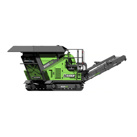
- Page 1 Bison 120 MOBILE CRUSHER Operations Manual Issue Date: 20-07-2018 Language: English (en) Revision No.: Original Intructions © Terex 2018...
- Page 2 EvoQuip 200 Coalisland Road Dungannon, Co. Tyrone BT71 4DR Telephone: +44 (0) 28 8774 0701...
- Page 3 Record of Revisions Record of Revisions Revision Number Reason for Change Date Introduction of the new Bison 120 manual August 2016 Start Up Procedure Update 2 May 2017 Maintenance Updates Greasing Schedule Updates Other General Updates California 65 Proposition updated. Safety Decals added. 20 July 2018 Emergency Stop Locations Updated.
- Page 4 Record of Revisions Intentionally Left Blank 20-07-2018 Operations Manual Revision 2.0 Page 2 Bison 120...
-
Page 5: Table Of Contents
Table of Content Table of Content Introduction ....................1-2 Notes to the Operations Manual..............1-2 Units......................1-2 Optional Equipment ...................1-3 Safety Information ..................1-3 Safety Warning Symbol ................1-3 (2) ANSI Hazard Classification System ............1-3 California Proposition 65 Warnings ............1-4 Intended Use ....................1-4 Prohibited Use ....................1-4 Declaration of Conformity ................1-4 Warranty ......................1-4 Copyright ......................1-5 Bulletin Distribution and Compliance..............1-5... - Page 6 Table of Content Technical Data .................... 3-2 3.1 Machine Specifications ...................3-2 (1) Machine Components Specifications ............3-2 Jaw Crusher ..................3-2 Grizzly Feeder with Hopper ..............3-2 Power Unit ....................3-3 Extracting Belt ..................3-3 Tracks ......................3-3 Dimensions .....................3-4 Working Range and Transport Diagrams ..........3-4 Noise Emissions .....................3-5 Operating Temperature Range ...............3-5 Machine Description ..................
- Page 7 Table of Content Removing Machine from the Low Loading Trailer ........5-14 Tracking the Machine off the Transporter ..........5-15 Lifting Machine off the Trailer ..............5-16 Initial Setup and Adjustments ..............6-2 Initial Inspection Check ..................6-3 Machine Location Considerations ..............6-3 Measures Before Setup..................6-4 Measures After Long-Term Standstill .............6-4 Pre-Operating checks ..................6-5 Checking Engine Oil Level ................6-5...
- Page 8 Table of Content Maintenance ....................9-3 General Information ..................9-4 Diesel Engine ....................9-5 Crusher ......................9-5 Vibrating Drawer ..................9-5 Extraction Belt....................9-5 Maintenance Schedule ...................9-6 Greasing Schedule ..................9-7 Lubricants, Oils, and Fluids ................9-11 Lubrication, Quantities, and Levels ............9-11 Machine Grease Lubrication ..............9-12 Standard Viscosity Option ..............9-12 Hydraulic Maintenance .................9-13 Hydraulic System Overview ..............9-14...
- Page 9 Table of Content Fuel System Maintenance ...............9-44 Changing the Fuel Filter ..............9-44 Draining Water from Fuel System ............9-45 Checking for Leaks ..................9-47 Fuel System Maintenance (Tier 4 Engine) ..........9-47 Draining Water from Fuel System (Tier 4 Engine) ......9-47 Bleeding the Fuel System ..............9-48 Changing the Fuel Filter (Tier 4 Engine) ..........9-49 Changing the Pre-Fuel Filter ...............9-50 9.10 Track Maintenance ..................9-51...
- Page 10 Table of Content Storage ......................11-2 Glossary of Terms ................... 12-1 Appendix ....................13-1 Appendix A EC Declaration of Conformity ..........A-1 Appendix B Warranty ................B-1 Appendix C Schematics ................C-3 Electrical Schematics................C-3 Front Panel- CPU Connection ............. C-3 Front Panel- CPU Connection (Cont.) ..........C-4 Main Wiring ..................
- Page 11 Introduction 1 Table of Content Introduction ....................1-2 Notes to the Operations Manual..............1-2 Units......................1-2 Optional Equipment ...................1-3 Safety Information ..................1-3 Safety Warning Symbol ................1-3 (2) ANSI Hazard Classification System ............1-3 California Proposition 65 Warnings ............1-4 Intended Use ....................1-4 Prohibited Use ....................1-4 Declaration of Conformity ................1-4 Warranty ......................1-4 Copyright ......................1-5 Bulletin Distribution and Compliance..............1-5...
-
Page 12: Introduction
NOT designed and/or constructed by Terex. In these circumstances, or where supplied as a replacement machine, Terex is NOT responsible for addressing environmental issues and/or health and safety protection measures for the machine installation as a whole. -
Page 13: Optional Equipment
Introduction 1 Optional Equipment Terex machines can include optional equipment and/or special features additional to the standard specification. These may affect the information given in this operations manual. Refer to Chapter 4 of the operations manual for extra equipment or variations that can be applicable to the standard specification. Take note of any variations to the standard procedures and/or component specifications. Safety Information Safety Warning Symbol The safety alert symbol is used on safety signs and throughout this manual to alert you to potential personal injury hazards. -
Page 14: California Proposition 65 Warnings
1 Introduction California Proposition 65 Warnings WARNING Operating, servicing and maintaining this equipment can expose you to chemicals including engine exhaust, carbon monoxide, phthalates, and lead, which are known to the State of California to cause cancer and birth defects or other reproductive harm. These chemicals can be emitted from or contained in other various parts and systems, fluids and some component wear by-products. -
Page 15: Copyright
Introduction 1 Copyright The copyright of this operations manual is reserved by Terex. This operations manual contains information and technical drawings, which may not be copied, distributed, altered, stored on electronic media, revealed to others or used for the purpose of competition, either partially or in its entirety. -
Page 16: Contacting The Manufacturer
1 Introduction Contacting the Manufacturer At times it may be necessary to contact the manufacturer of this machine. When you do, be ready to supply the model number and PIN number of your machine, along with your name and contact information. - Page 17 Safety 2 Table of Content Safety ......................2-2 Safety Warning Symbol ................2-2 (2) ANSI Hazard Classification System ............2-2 Property Damage Messages ..............2-3 Positions of Safety Signs on the machine ..........2-3 Personal Safety ....................2-8 Personal Protective Equipment ..............2-8 Work Area Safety ...................2-9 General Work Area Guidelines ..............2-9 Safety Warnings and Labels ..............2-9 (3) Modifications ....................2-9...
-
Page 18: Safety
Where the machine is supplied for incorporation into equipment designed, supplied and located by others, Terex cannot be aware of particular hazards. These hazards can be present or can occur and therefore Terex accepts no liability for addressing or resolving these issues. -
Page 19: Property Damage Messages
Safety 2 Property Damage Messages The signal word NOTICE, shown without the safety alert symbol, is used throughout this manual and on machine labels to address specific practices, or draw attention to supplemental information that is not related to personal injury. NOTICE NOTICE - indicates information considered important, but not hazard related (e.g., messages related to property damage). - Page 20 2 Safety Item Safety Sign Meaning Risk of hand entrapment Possible stones projection Do not remove casings or safety protection. Lifting points Danger of high temperatures 20-07-2018 Operations Manual Revision 2.0 Page 2-4 Bison 120...
- Page 21 Safety 2 Item Safety Sign Meaning Direction of movement Danger of parts in motion. DANGER - Moving parts! Stop the engine. Always wear helmet, gloves and working garments Lubrication label Operations Manual 20-07-2018 Revision 2.0 Page 2-5 Bison 120...
- Page 22 2 Safety Item Safety Sign Meaning Access prohibited to those wearing pacemakers (when a magnetic belt has been installed on the machine). Anchorage points Battery WARNING Cancer and Reproductive Harm - www.P65Warnings.ca.gov 1021008009 20-07-2018 Operations Manual Revision 2.0 Page 2-6 Bison 120...
- Page 23 Safety 2 Figure 2.1 - Location of Safety Signs Operations Manual 20-07-2018 Revision 2.0 Page 2-7 Bison 120...
-
Page 24: Personal Safety
2 Safety Personal Safety Ascertain from the appropriate authority and observe all statutory and any other regulations that apply to the planned location before operating the machine. Operators must be trained and competent in the correct and safe use of all equipment. Before operation, the operator must: •... -
Page 25: Work Area Safety
Safety 2 Work Area Safety General Work Area Guidelines Operators must have received specific training in all operating and service tasks as required for the safe operation and service of the machine. Operators must know the location and correct operation of all controls and safety features such as remote stop buttons and isolator switches. Operators must be aware of all moving parts on the machine. -
Page 26: Transportation Safety
2 Safety Transportation Safety NOTICE Always check the machine for loose or damaged components before transportation. Ensure all loose items which are transported with the machine are transported on the machine. Check that the transport dimensions and weight of the machine are within the regulation limits. Failure to comply can result in damaging the machine. - Page 27 Safety 2 Before moving the machine, ensure that everyone is clear from the surrounding area. Ensure that the warning siren and beacon and the remote control machine stop button are operating correctly. Make certain enough ventilation is present to run engines safely. Do not start an engine in an enclosed space without properly vented exhaust.
-
Page 28: Hydraulic And Pneumatic Safety
2 Safety Hydraulic and Pneumatic Safety Only persons having special knowledge and experience in hydraulic and pneumatic systems must carry out work on hydraulic and pneumatic equipment. Never disable or alter any hydraulic circuit or component without consulting with EvoQuip. Relieve all pressure in the hydraulic system by returning all controls to the neutral position. -
Page 29: Electrical Safety
Safety 2 Electrical Safety Work on the electrical system or equipment can only be carried out by a skilled and qualified electrician or by specially instructed personnel under the control and supervision of such an electrician. Work on the electrical system must be in accordance with applicable electrical engineering rules and regulations. Use only original fuses with the specified current rating. Switch off the machine immediately if trouble occurs in the electrical system. Machines with high-voltage electrical equipment must be suitably earth bonded by a qualified electrician before activating the main isolator switch. -
Page 30: Maintenance Safety
2 Safety Maintenance Safety Understand the service procedures before doing work. Keep working area clean and dry. Never lubricate, clean, service, or adjust machinery while it is operating unless specified in this manual. Keep hands, feet, and clothing clear of power-driven parts and in running nip-points. Disengage all power and operate controls to relieve pressure. Stop the engine, implement the lockout and tag out procedure and allow the machinery to cool before carrying out any maintenance. - Page 31 Safety 2 When the machine is completely shutdown for maintenance and repair work, it must be secured against inadvertent starting by: • Switching off the engine and removing the ignition key or isolating the electrical supply as applicable. • Implementing the lockout and tagout procedure. •...
-
Page 32: Gas, Dust, Steam, Smoke
2 Safety Gas, Dust, Steam, Smoke Death, serious injury or delayed lung disease may result from breathing dusts that are generated when certain hazardous materials are crushed, screened or conveyed with this equipment. Diesel engine exhaust emissions contain products of combustion which may be harmful to your health. -
Page 33: (12) Fire Hazards
Safety 2 (12) Fire Hazards NOTICE This machine has many positions where a fire extinguisher can be fitted. The fire extinguisher is provided by the end user and not by Evoquip. Holes are required to be drilled for the fire extinguisher mounting brackets and caution must be taken. There are hydraulic hoses and pipes on the opposite side of the recommended mounting area. When the holes are drilled, they are to be threaded to allow the fire extinguisher bracket to be securely mounted. It is the owners responsibility to ensure that the fire extinguishers fitted are adequate for the following types of combustible materials on the machine: •... -
Page 34: (13) Exclusion Zones
2 Safety (13) Exclusion Zones Magnet DANGER Strong Magnetic Field Hazard. Strong magnetic field can disrupt pacemaker operation and result in serious injury or death to a pacemaker wearer. STAY CLEAR FROM MAGNET. The operator must stand out of the exclusion zones while the machine is operating. The magnetic field can disturb pacemaker operation if within 3 metres. WARNING Flying Material Hazard Materials discharged from the magnet can result in serious injury or death. NOTICE The operator must stay clear of the magnet while in operation. -
Page 35: Emergency Stop Locations
Safety 2 Emergency Stop Locations Emergency stops are located at both the left hand side and right hand side of the machine. Further emergency stops are located on the control panel and radio control panel. DUN03194 Figure 2.3 - Emergency Stop Location DUN03195 Figure 2.4 - Emergency Stop Location Operations Manual... - Page 36 2 Safety Intentionally Left Blank 20-07-2018 Operations Manual Revision 2.0 Page 2-20 Bison 120...
- Page 37 Technical Data 3 Table of Content Technical Data .................... 3-2 3.1 Machine Specifications ...................3-2 (1) Machine Components Specifications ............3-2 Jaw Crusher ..................3-2 Grizzly Feeder with Hopper ..............3-2 Power Unit ....................3-3 Extracting Belt ..................3-3 Tracks ......................3-3 Dimensions .....................3-4 Working Range and Transport Diagrams ..........3-4 Noise Emissions .....................3-5 Operating Temperature Range ...............3-5 Operations Manual...
-
Page 38: Technical Data
3 Technical Data Technical Data Every endeavour will be made to supply equipment as specified, but we reserve the right, where necessary, to amend specifications without prior notice as we operate a policy of continual product development. It cannot be guaranteed that the plant will meet any specific requirements in respect of noise or vibration levels, dust emissions, or any other factors relevant to health and safety measures or environmental protection needs. The technical data given in this section are given as approximations for reference only. Machine Specifications Weight (approximate) Complete Machine... -
Page 39: (C) Power Unit
Technical Data 3 Power Unit Tier 3 Tier 4 Engine Isuzu turbo engine Isuzu turbo engine Performance 61kW (83hp) 52kW (70hp) Operating rpm range 1500-2500 rpm 2000 rpm (maximum) Plant drive Hydraulic drive Hydraulic drive Extracting Belt Belt Length 6340 mm (20’ 10”) Belt Width 800 mm (32”) Discharge height... -
Page 40: Dimensions
3 Technical Data Dimensions Working Range and Transport Diagrams Figure 3.1 - Working Range and Transport Dimensions 20-07-2018 Operations Manual Revision 2.0 Page 3-4 Bison 120... -
Page 41: Noise Emissions
Technical Data 3 Noise Emissions WARNING Danger of hearing damage When working directly beside the crusher or on its platforms, the permissible daily noise exposure level (LEX,8h) of 80 dB is exceeded. Bison 120 @1800 RPM Declared Single-Number Noise Emission Values In accordance with ISO 4871 A-Weighted sound power level, LWAd (ref. - Page 42 3 Technical Data Intentionally Left Blank 20-07-2018 Operations Manual Revision 2.0 Page 3-6 Bison 120...
- Page 43 Machine Description 4 Table of Content Machine Description .................. 4-2 General Information ..................4-2 Machine References ..................4-3 Machine Components ................4-4 Systems ......................4-5 Power Unit ....................4-5 Crushing System ..................4-5 Jaw Crusher ..................4-5 Dust Eliminating System (Optional) ............4-5 Feed System....................4-5 Vibrating Feeder..................4-5 Conveying System ..................4-5 Extracting Belt ..................4-5 Magnetic Belt (Optional) ...............4-5 Twin Track Undercarriage ................4-6...
-
Page 44: Machine Description
4 Machine Description Machine Description General Information This machine has been designed for stone crushing applications, to maximise throughput and product shape in a wide rage of quarrying applications. Its features include: • Suitable for many sizes of rock or stone materials. •... -
Page 45: Machine References
Machine Description 4 The machine identification plate is located on the Rear Right Hand side of the machine (Item 1) . Figure 4.2 - Location of Machine Identification Plate Machine References When using this handbook, at all times the right and the left hand references are viewed from the feeder end of the machine. When using this handbook, at all times the rear of the machine is situated at the feeder end. DUN02743 Figure 4.3 - Machine References Left hand side... -
Page 46: Machine Components
4 Machine Description Machine Components The following sections identify the main components of the machine and the term with which theyare referred to in this manual. OMA03846 Figure 4.4 - Machine Components Item Description Item Description Undercarriage Service ladder Extraction belt Evacuator belt (not applicable) Vibrating drawer Open able back door... -
Page 47: Systems
Machine Description 4 Systems Power Unit The power unit is attached to the chassis of the machine alongside the crusher. The power unit is completely enclosed, sound suppressed and lockable. The power unit contains the Isuzu turbo engine. Hydraulic power is provided from the engine to drive both conveyors, operate the hydraulic cylinders and give power to the tracks. -
Page 48: Twin Track Undercarriage
4 Machine Description Twin Track Undercarriage The machine is mounted on and driven by a high specification tracked undercarriage fitted with transmittal gearboxes with integrated brake and over centre valve. The movement of the machine is controlled by a handheld radio control transmitter.. Maintenance Platform Provided for inspection and maintenance, allowing safe access to the top of the crusher. It is made from steel flooring with steel toe boards, double row handrails and access ladders. -
Page 49: Control And Display Elements
Machine Description 4 Control and Display Elements Control Panel The crushing control is fully integrated into the machine control system. This enables crushers functions to be controlled easily. Figure 4.5 - Tier 4 Control Panel Item Function Multifunction Display Glow Light Ignition Key Accelerator Potentiometer Extractor belt opening/closing lever... -
Page 50: Radio Control
4 Machine Description Radio Control A Radio control unit is provided for controlling the tracking function. It provides a tracking speed of approximately 1 kilometer per hour and a ‘creep’ facility for loading, off loading and precise slewing movements. Figure 4.6 - Umbilical Handset Command Function Item 1... -
Page 51: Optional Equipment
Machine Description 4 Optional Equipment Protective sides for the loading hopper Figure 4.7 - Hopper Protector Magnetic belt: a magnetic belt can be installed to separate out materials containing iron, which is thus captured and discharged from the side. Figure 4.8 - Magnetic Belt Dust elimination system: the plant can be equipped with a water system that will be sprayed on the material to be crushed using nozzles reducing the dust in the crushing process. -
Page 52: Applications
4 Machine Description Figure 4.9 - Dust Suppression Applications The Evoquip range of high performance primary jaw crushing machines are designed for small and medium scale operators in quarrying, demolition, recycling & mining applications. The applications in which it can be used for are as follows: Aggregate •... - Page 53 Transportation 5 Table of Content Transportation .................... 5-2 Placing the Machine into the Transport Position ..........5-4 Placing The Extraction Belt Into Transport Position ........5-5 Loading the Machine for Transport..............5-8 Prior to Haulage ..................5-8 Tracking Machine onto Trailer ..............5-9 Lifting Machine onto Trailer ..............5-10 Ready for Transport .................5-12 Transport Tie-Down Points ..............5-13 Removing Machine from the Low Loading Trailer ........5-14...
-
Page 54: Transportation
5 Transportation Transportation WARNING Nip Point Hazard. Nip points exist where pins and rams need to be reconnected. Moving Object Hazard. When lifting any heavy sub assemblies there is always risk of the object unexpectedly moving. Ensure adequate distance is kept from the assembly when being raised from the ground. Failure in doing so may result in serious injuries. - Page 55 Transportation 5 Preparation Prior to Transportation CAUTION Prior to transportation always check the machine for loose or damaged components. Ensure all loose items are carefully stowed and secured if these are to be transported on the machine. Check that the travelling dimensions and weight of the machine will be within the regulation limits. Before transporting the machine, observe the prescribed transport position, admissible speed and itinerary.
-
Page 56: Placing The Machine Into The Transport Position
5 Transportation Placing the Machine into the Transport Position Prior to transportation the machine must be put into the transport position. DANGER Use a suitable maintenance platform when working at a height. Do not climb onto working or moving machinery. Use appropriate lifting equipment of adequate capacity. -
Page 57: Placing The Extraction Belt Into Transport Position
Transportation 5 Placing The Extraction Belt Into Transport Position WARNING Always wear appropriate personnel protective equipment. NOTICE Faults displayed on the electrical control panel screen should be investigated and rectified immediately by suitably qualified personnel. PROCEDURE Observe all safety warnings. Ensure that all of the emergency stop buttons have been released. Turn the isolator switch to the “ON”... - Page 58 5 Transportation Ensure that all function toggle switches are in the off position and that the chamber switch is in neutral position. Turn the ignition key (Item 1) of the radio control to 1, Reference: Figure 5.3. » The LED light on the handset will be flashing at a fast speed which means the handset is not connected .
- Page 59 Transportation 5 Figure 5.5 - Accelerator Potentiometer 12. Keep the engine ticking over on idle for few minutes to warm it. The number of revolutions will appear at the top of the multifunction display. 13. On the radio remote push the extraction belt open/close lever (Item 1) forward until belt has folded completely into transport position, Reference: Figure 5.6.
-
Page 60: Loading The Machine For Transport
5 Transportation Loading the Machine for Transport WARNING Crush Hazard Always wear appropriate personnel protective equipment. NOTICE Before transportation of the machine, check for loose or damaged components. Fasten all loose parts, replace missing items or make repairs as found necessary to ensure that all components are secured during transportation. -
Page 61: Tracking Machine Onto Trailer
Transportation 5 Tracking Machine onto Trailer NOTICE If using slides to raise the machine on to the trailer they must be anchored to the body to allow the machine to be raised or lowered. The length of the slide must be such as to form an angle of 12°-15°... -
Page 62: Lifting Machine Onto Trailer
5 Transportation Figure 5.8 - Transport Tie Down Points Lifting Machine onto Trailer NOTICE In order to load or unload the machine into and from a lorry, the lifting points on the chassis can be used, ensuring that a harness of adequate resistance to the weight to be lifted. It is recommended to use a spreader frame to minimize the risk of damaging the machine when lifting. - Page 63 Transportation 5 Figure 5.9 - Lifting Machine on Trailer Ensure that all loose items are carefully stowed and secured if these are to be transported on the machine. Using suitable lifting equipment, lift the crusher on to the back of the transporter. Secure the machine using the tie down transport brackets and all loose items to the transporter.
-
Page 64: Ready For Transport
5 Transportation Ready for Transport WARNING Do not transport this machine without it being properly secured on to the lowloader. Before transporting this machine you must read and understand the Safety section in this manual. NOTICE Before tracking the machine ensure the engine speed is at idle or on slow tracking mode for machines with a constant speed engine. -
Page 65: Transport Tie-Down Points
Transportation 5 Transport Tie-Down Points NOTICE When transporting the machine, it is the responsibility of the haulage contractor to secure the machine to the transporter. This machine is fitted with transport tie down brackets, the brackets are indicated on the machine by a safety symbol. OMA00588 Figure 5.12 - Transport Tie Down Point Symbol Operations Manual 20-07-2018 Revision 2.0 Page 5-13... -
Page 66: Removing Machine From The Low Loading Trailer
5 Transportation Removing Machine from the Low Loading Trailer WARNING Wear personal protective equipment. Ensure all personnel are clear from the machine. NOTICE Removing the fastenings securing the machine and any loose items from a trailer is the responsibility of the haulage contractor. All control levers must be in the neutral (non-operational) position. -
Page 67: Tracking The Machine Off The Transporter
Transportation 5 Tracking the Machine off the Transporter PROCEDURE Observe all safety warnings. Position suitable ramps at the end of the transporter. Remove the fastenings securing the machine to the transporter. Figure 5.13 - Transport Tie Down Points Start the engine. Ensure the engine speed is at idle. -
Page 68: Lifting Machine Off The Trailer
5 Transportation Lifting Machine off the Trailer NOTICE In order to load or unload the machine into and from a lorry, the lifting points on the chassis can be used, ensuring that a harness of adequate resistance to the weight to be lifted. It is recommended to use a spreader frame to minimize the risk of damaging the machine when lifting. - Page 69 Initial Setup and Adjustments 6 Table of Content Initial Setup and Adjustments ..............6-2 Initial Inspection Check ..................6-3 Machine Location Considerations ..............6-3 Measures Before Setup..................6-4 Measures After Long-Term Standstill .............6-4 Pre-Operating checks ..................6-5 Checking Engine Oil Level ................6-5 Checking Diesel Level ................6-6 Checking Hydraulic Oil Level Check ............6-7 Checking Track Tension ................6-7 Setting Up the Machine ..................6-8...
-
Page 70: Initial Setup And Adjustments
Check in and around the machine for any loose items that have been shipped inside the machine. Terex recommends that the assembly and installation work of the machine is carried out by the Terex customer service department. The manufacturer/supplier is not liable for damage caused by improper assembly or installation. -
Page 71: Initial Inspection Check
Initial Setup and Adjustments 6 Initial Inspection Check WARNING Observe all safety warnings while carrying out inspections and checks. Wear personal protective equipment. NOTICE When the machine is delivered, thoroughly check for any damage that has occurred during transport. Do not set up the unit until the inspection is complete. Complete any delivery and start- up forms that were supplied with the equipment. -
Page 72: Measures Before Setup
6 Initial Setup and Adjustments Measures Before Setup NOTICE Evoquip recommends that the Evoquip customer service department carries out the assembly and installation work of the machine. The manufacturer/supplier are not liable for damage caused by improper assembly/installation. • Ensure that all guards are fully secured in correct/closed position. •... -
Page 73: Pre-Operating Checks
Initial Setup and Adjustments 6 Pre-Operating checks NOTICE Before starting-up the machine, perform all checks and personally verify that the machine is in perfect working order. In particular we recommend you: • Check the engine oil level • Check the diesel level •... -
Page 74: Checking Diesel Level
6 Initial Setup and Adjustments Checking Diesel Level DANGER Highly Flammable Substance. Avoid naked flames when working on the fuel system. Do not smoke. Risk of fire or explosions, resulting in serious injuries or death. PROCEDURE Observe all safety warnings. Position the machine in a flat, safe place. Check that on the visual indicator (Item 1) on the outside of the tank. Top up fuel as required through the refill cap (Item 2). -
Page 75: Checking Hydraulic Oil Level Check
Initial Setup and Adjustments 6 Checking Hydraulic Oil Level Check PROCEDURE Observe all safety warnings. Position the machine in a flat, safe place. Check that on the visual indicator (Item 1) on the outside of the tank. Top up hydraulic oil as required through the refill cap (Item 2,). -
Page 76: Setting Up The Machine
6 Initial Setup and Adjustments Setting Up the Machine WARNING Injection Hazard. Fluid escaping under pressure can penetrate skin and result in death or serious injury. Relieve pressure before disconnecting hydraulic lines. Stay clear of leaks and pin holes. Use a piece of cardboard or wood to search for leaks. Do not use hand. -
Page 77: Setup
Initial Setup and Adjustments 6 Setup Starting the Engine WARNING Always wear appropriate personnel protective equipment. NOTICE Faults displayed on the electrical control panel screen should be investigated and rectified immediately by suitably qualified personnel. PROCEDURE Observe all safety warnings. Ensure that all of the emergency stop buttons have been released. Turn the isolator switch to the “ON”... - Page 78 6 Initial Setup and Adjustments Check that the green power light is illuminated on the receiver inside the door on the opposite side of the machine from control panel. Ensure that all function toggle switches are in the off position and that the chamber switch is in neutral position.
-
Page 79: Placing The Extraction Belt Into Working Position
Initial Setup and Adjustments 6 Figure 6.9 - Accelerator Potentiometer 12. Keep the engine ticking over on idle for few minutes to warm it. The number of revolutions will appear at the top of the multifunction display. Placing the Extraction Belt Into Working Position WARNING Always wear appropriate personnel protective equipment. -
Page 80: Setting The Crusher Discharge Opening
6 Initial Setup and Adjustments Setting the Crusher Discharge Opening WARNING Nip Point Hazard. Ensure all crusher guards are securely fitted and personnel stay clear of the machine when adjusting the discharge opening. NOTICE The size of the crushed aggregates can be regulated by bringing the mobile jaw closer to, or moving it further away from the fixed jaw. -
Page 81: Introducing Material To Machine
Initial Setup and Adjustments 6 Introducing Material to Machine WARNING Before operating the machine, read, and understand the operator manual. NOTICE Avoid any contact with the shovel, excavator, or ramp against the side of the machine. PROCEDURE Some operators build a ramp at the side / end of the machine to give their shovel loader a better reach into the hopper (Item 1). -
Page 82: Initial Startup And Running In
6 Initial Setup and Adjustments 6.10 Initial Startup and Running In WARNING Observe all safety warnings while carrying out inspections and checks. Wear personal protective equipment. Shut down the machine when errors occur and investigate the reason. If necessary, contact Evoquip help desk department for advice to avoid the possibility of danger or damage. - Page 83 Standard Operating Procedures 7 Table of Content Standard Operating Procedures .............. 7-2 Pre Operating Checks ..................7-3 Initial Startup ....................7-4 Start Up ......................7-5 Manoeuvring ....................7-8 Tracking the Machine ................7-9 Remote Tracking..................7-10 Remote Tracking with Umbilical Cable ............7-12 Standard Operation via Radio Remote ............7-13 Shutdown .....................7-15 Stalled Crusher Procedure ................7-18 20-07-2018...
-
Page 84: Standard Operating Procedures
7 Standard Operating Procedures Standard Operating Procedures General Information n WARNING Wear personal protective equipment (PPE) when operating this machine. Refer to Chapter 2, Personal Protective Equipment earlier in this manual for a list of prescribed PPE. Before attempting to operate the machine, DO read, fully understand, and observe the contents of this manual. -
Page 85: Pre Operating Checks
Standard Operating Procedures 7 Pre Operating Checks n DANGER DO not stand on the maintenance platform whilst the machine is operating. n WARNING Wear personal protective equipment. Fall hazard. Switch off, tag out and lock out machine before carrying out pre-operating checks. NOTICE AVOID frequent starting and stopping of the machine unnecessarily as it WILL cause damage to the machine. -
Page 86: Initial Startup
These checks must be carried out before operating the machine. This section should be read and understood prior to starting the machine. If there are any doubts, consult your local dealer or Terex Technical Support department. PROCEDURE Refer to the engine manufacturer’s manual for initial start up of the engine. -
Page 87: Start Up
Standard Operating Procedures 7 Start Up NOTICE Faults displayed on the electrical control panel screen should be investigated and rectified immediately by suitably qualified personnel. PROCEDURE Observe all safety warnings. Ensure that all of the emergency stop buttons have been released. Turn the isolator switch to the “ON” position (Item 1). Figure 7.1 - Isolator Switch Turn the ignition key (Item 1) on the dashboard to ON. - Page 88 7 Standard Operating Procedures » The LED light on the handset will be flashing at a fast speed which means the handset is not connected . Figure 7.3 - Radio Ignition Switch Press button 2 to connect the handset to the reciever, Reference: Figure 7.3. The green LED on the handset will now be flashing slowly and the blue “STATUS”...
- Page 89 Standard Operating Procedures 7 Figure 7.5 - Accelerator Potentiometer 12. Keep the engine ticking over on idle for few minutes to warm it. The number of revolutions will appear at the top of the multifunction display. 20-07-2018 Operations Manual Revision 2.0 Page 7-7 Bison 120...
-
Page 90: Manoeuvring
7 Standard Operating Procedures Manoeuvring n DANGER DO NOT stand on any of the platforms or ladders of the machine whilst it is being manoeuvred using the remote control handset. When manoeuvring your machine to its operating position make sure you stand well clear of the machine but are in a position to have all-round vision to see any obstacles or dangers that may lie ahead e.g. -
Page 91: Tracking The Machine
Standard Operating Procedures 7 Tracking the Machine n DANGER Nip Point Hazard Hazardous nip points exist. Under no circumstances must the machine be running when preforming the following tasks. Failure in doing so may result in serious injuries. Switch off the machine and implement the lockout and tagout procedure. -
Page 92: Remote Tracking
7 Standard Operating Procedures Remote Tracking Remote control console function is ensured by a rechargeable battery. Two batteries are supplied as standard. We recommend you always keep a battery charged to replace the one in use regularly. It is advisable to let the battery run down completely before recharging. PROCEDURE Observe all safety warnings. - Page 93 Standard Operating Procedures 7 The following list identifies the machines directions. Use the list with the diagram. • 1-Left • 2-Forward • 3-Right • 4-Right-Hand Side Track • 5-Reverse • 6-Left-Hand Side Track To move the tracks press the directional buttons (Items 1-4). Figure 7.9 - Umbilical Handset Functions The radio handset functions are as follows: Position 1 = Left-Hand Side Track Forward Position 2 = Right-Hand Side Track Forward Position 3 = Left-Hand Side Track Reverse...
-
Page 94: Remote Tracking With Umbilical Cable
7 Standard Operating Procedures Remote Tracking with Umbilical Cable NOTICE Should the battery run flat and you do not have an available replacement, the machine can function by connecting a cable (supplied) from the radio control console to the central unit. PROCEDURE Observe all safety warnings. Unroll the supplied connection cable and connect one end to the control panel of the machine and the other to the radio remote. -
Page 95: Standard Operation Via Radio Remote
Standard Operating Procedures 7 Standard Operation via Radio Remote Before operating the machine, ensure to read and understand the operators manual. Before, starting the engine ensure that all conveyor belts are sufficiently tensioned. Before loading material onto the hopper, the entire machine must be running. When all components of the machine have been put into operation, allow the machine to run empty for a short period of time to check for abnormal noises, vibration or excessive heat from the shaft bearings, fluid leaks, etc. - Page 96 7 Standard Operating Procedures Figure 7.12 - Chamber Start Button If fitted with optional magnetic belt, press the start button (Item 1), Reference: Figure 7.13. This will start the magnetic belt. Figure 7.13 - Chamber Start Button On the radio remote press the vibrating drawer start button (Item 1). This will start the vibrating drawer.
-
Page 97: Shutdown
Standard Operating Procedures 7 Shutdown At the end of operation for the day it is recommended that the machine is routinely cleaned down and checked for damage. It must also be checked for wear or leaks and fixed before further operation. - Page 98 7 Standard Operating Procedures Turn the ignition key (Item 1) of the radio control OFF. Figure 7.17 - Radio Ignition Switch Turn the ignition key (Item 1) on the dashboard to OFF. Figure 7.18 - Ignition Switch Wait for at least 20 seconds before turning the isolator switch to the off position. 20-07-2018 Operations Manual Revision 2.0...
- Page 99 CAUTION To comply with health and safety law it is necessary to carry out adequate risk assessments of the procedures for unblocking a crusher. It is the responsibility of the owner, machine operator and safety officer of the Terex ® Evoquip crusher to provide a safe means of unblocking a stalled crusher unit.
-
Page 100: Stalled Crusher Procedure
7 Standard Operating Procedures Stalled Crusher Procedure n DANGER Cutting through the toggle plate (Step 6 below) will cause the release of stored energy in the moving jaw which may swing back with strong force towards the operator performing the cutting operation. - Page 101 Standard Operating Procedures 7 The toggle plate should heated across the centre line (i.e. between the holes), using a long- handled ‘oxy acetylene torch’ or similar, such that the operator can stand in a protected position, preferably to the side of the plant. Heat the material to a dull red - starting at the mid-point, and working outwards either side in turn.
- Page 102 7 Standard Operating Procedures Intentioanlly Left Blank 20-07-2018 Operations Manual Revision 2.0 Page 7-20 Bison 120...
- Page 103 Emergency Operating Procedures 8 Table of Content Emergency Operating Procedures ............8-2 Lockout and Tagout ..................8-2 Before Carrying Out Any Work on the Machine .........8-2 After Carrying out Work on the Machine ............8-4 Emergency Stop .....................8-5 Emergency Stop Locations ................8-5 Restarting after Emergency Stop ..............8-6 Testing Emergency Stops ................8-6 20-07-2018...
-
Page 104: Emergency Operating Procedures
8 Emergency Operating Procedures Emergency Operating Procedures Lockout and Tagout This procedure is designed to prevent injuries caused by the unexpected start-up or movement of a machine. These procedures are to be followed every time a machine is to be cleaned,maintained, adjusted or repaired. - Page 105 Emergency Operating Procedures 8 Figure 8.2 - Radio Ignition Switch 4. Unlock and open the battery door. 5. After 20 seconds, rotate the isolator switch from the OFF position (Item 1) to the ON position (Item 2), Reference: Figure 8.3. Figure 8.3 - Isolator Switch 6.
-
Page 106: After Carrying Out Work On The Machine
8 Emergency Operating Procedures 7. Lock the battery door (Item 1). Always keep the key on person, ensuring that no one can remove your lock and turn the power back on. Figure 8.5 - Battery Door 8. Release stored energy from the system so that the machine is in a zero energy state. 9. -
Page 107: Emergency Stop
Emergency Operating Procedures 8 Emergency Stop n WARNING The stop button on the remote radio control, if fitted, is NOT an emergency stop as it may not be operative at all times. When an emergency stop has been initiated, the ignition switch stays on. Do not attempt to restart the engine until it is safe to do so. Do not hit an emergency stop button unless it is an emergency. Repeated use of the emergency stop button could cause damage to the engine. -
Page 108: Restarting After Emergency Stop
8 Emergency Operating Procedures DUN03195 Figure 8.7 - Emergency Stop Location Restarting after Emergency Stop n WARNING Ensure that the problem has been solved and all personnel are clear of the machine. correctly fitted and fully functional. Before restarting, ensure that all guards are Ensure there is no material in and/or on the machine before restarting, including material in the crusher or feed hopper or on the conveyors and platform walkway. - Page 109 Maintenance 9 Table of Content Maintenance ....................9-3 General Information ..................9-4 Diesel Engine ....................9-5 Crusher ......................9-5 Vibrating Drawer ..................9-5 Extraction Belt....................9-5 Maintenance Schedule ...................9-6 Greasing Schedule ..................9-7 Lubricants, Oils, and Fluids ................9-11 Lubrication, Quantities, and Levels ............9-11 Machine Grease Lubrication ..............9-12 Standard Viscosity Option ..............9-12 Hydraulic Maintenance .................9-13 Hydraulic System Overview ..............9-14...
- Page 110 9 Maintenance Changing Coolant ................9-41 Changing Coolant (Tier 4 Engine) ............9-42 Fuel System Maintenance ...............9-44 Changing the Fuel Filter ..............9-44 Draining Water from Fuel System ............9-45 Checking for Leaks ..................9-47 Fuel System Maintenance (Tier 4 Engine) ..........9-47 Draining Water from Fuel System (Tier 4 Engine) ......9-47 Bleeding the Fuel System ..............9-48 Changing the Fuel Filter (Tier 4 Engine) ..........9-49 Changing the Pre-Fuel Filter ...............9-50...
-
Page 111: Maintenance
Maintenance 9 Maintenance Safety Before and During Maintenance n WARNING Practice safe maintenance. Read and understand the operators manual before doing any work. Maintenance should only be carried out by trained and qualified personnel. PROCEDURE Whenever maintenance or service is being carried out a minimum of two (2) persons should be present at all times. -
Page 112: General Information
9 Maintenance 16. NEVER make any modifications, additions or conversions which might affect safety without the supplier’s approval. 17. To prevent any burns or scalds allow the hydraulic oil to cool down before carrying out any maintenance tasks (approximately 3 hours). General Information Refer to Chapter 2 Safety for relevant safety information before attempting to carry out any maintenance on the machine. -
Page 113: Diesel Engine
Maintenance 9 When power or steam cleaning the machine be aware of the risk of damaging components i.e., electrical components , bearings. Water ingress or heat may penetrate or damage seals leading to premature failure. Remove any buildup of stones, dust, grease, oil, or other debris from the machine. Diesel Engine The diesel engine is the heart of your machine and a great deal of care and thought has gone into its selection. -
Page 114: Maintenance Schedule
9 Maintenance Maintenance Schedule Diesel Engine (Also see engine manual) Engine Oil Level Air Filter Engine Oil Filter Diesel Filter Coolant Crusher Belt Tension Tightening of plate clamping bolts Greasing Plate wear ... -
Page 115: Greasing Schedule
Maintenance 9 Greasing Schedule NOTICE Check the greasing equipment used regularly. Each grease gun will put out a differing amount. Check greasing equipment before use. It is important that a strict routine of regular servicing is undertaken from the start of operation of the machine. - Page 116 9 Maintenance Figure 9.2 - Grease Points (Cont.) 20-07-2018 Operations Manual Revision 2.0 Page 9-8 Bison 120...
- Page 117 Maintenance 9 POS. LOCATION/ FREQUENCY GREASE CAPACITY DESCRIPTION TYPE CONVEYOR - 8 HOURS 4 grams/2 pumps DRIVING ROLLER (LEFT SIDE) CONVEYOR - EVERY WEEK 4 grams/2 pumps FRAME PIN (LEFT SIDE) CONVEYOR - EVERY WEEK 4 grams/2 pumps FRAME PIN (LEFT SIDE) CONVEYOR –...
- Page 118 9 Maintenance POS. LOCATION/ FREQUENCY GREASE CAPACITY DESCRIPTION TYPE CONVEYOR - 8 HOURS 4 grams/2 pumps DRIVING ROLLER (RIGHT SIDE) LEFT VIBRATOR 8 HOURS 10 grams/5 pumps LEFT VIBRATOR 8 HOURS 10 grams/5 pumps RIGHT VIBRATOR 8 HOURS 10 grams/5 pumps RIGHT VIBRATOR 8 HOURS 10 grams/5 pumps...
-
Page 119: Lubricants, Oils, And Fluids
Maintenance 9 Lubricants, Oils, and Fluids n WARNING Injection Hazard. Fluid escaping under pressure can penetrate skin and result in death or serious injury. Relieve pressure before disconnecting hydraulic lines. Stay clear of leaks and pin holes. Use a piece of cardboard or wood to search for leaks. Do not use hand. -
Page 120: Machine Grease Lubrication
• Base oil type: MINERAL • Thickener type: LITHIUM SOAP (lithium complex can also be considered if supplier guarantees compatible and approved by Terex) • Base oil minimum viscosity (din 51561-1) @ 40°c (104°f) = 220 mm2/s • Base oil minimum viscosity (din 51561-1) @ 100° (212°f) = 17 mm2/s •... -
Page 121: Hydraulic Maintenance
Maintenance 9 Hydraulic Maintenance NOTICE Hydraulic fluids play an important part in any hydraulic system. They have two main functions to transmit power and to lubricate moving parts. As a power transmitting medium the fluid must flow easily and be as incompressible as possible. In most hydraulic components, the fluid provides internal lubrication only. For long component life, fluids are available containing additives that have high anti-wear properties. The fluids are known as anti-wear type hydraulic oils, which are recommended for your machine. In, most cases the fluid is the only oil seal present. For example, there are no sealing rings between the spool and the body of the directional valve. Sealing characteristics of the fluid depend on its retaining viscosity. It is important that the oils selected have the capabilities of maintaining the minimum viscosity change over a wide range of operating temperatures. -
Page 122: Hydraulic System Overview
9 Maintenance Hydraulic System Overview The Hydraulic system which is used in your machine was chosen for its effectiveness and resistance to climatic and operating conditions. This must be kept topped up with the correct hydraulic fluid and regular checks must be made to ensure this. The system should be checked for leaks and the hydraulic oil analyzed after 500 hours and replaced if necessary. -
Page 123: (B) Oil Tank, Pipes & Fittings
Maintenance 9 Oil Tank, Pipes & Fittings In order to prevent contamination, the Oil Tank on your machine is of sealed construction. Access to the tank, if required, is via inspection covers which are mounted on the top of the tank, underneath the filler cap. The outside of the tank must be thoroughly cleaned before the removal of any of these covers. -
Page 124: (B) Load Sensing Pump Oil Filter
9 Maintenance Load Sensing Pump Oil Filter A filter is fitted and matched to pump capacity. It Is fitted between the load sensing pump and the proportional distributor (Item 1). New filter element should be fitted at regular intervals (see routine maintenance schedule for frequency). Figure 9.5 - Load Sensing Pump Filter Tank Oil Filter A filter is fitted to the hydraulic oil tank (Item 1). New filter element should be fitted at regular intervals (see routine maintenance schedule for frequency). Figure 9.6 - Tank Filter 20-07-2018 Operations Manual Revision 2.0 Page 9-16 Bison 120... -
Page 125: Changing Hydraulic Filters & Oil
Maintenance 9 Changing Hydraulic Filters & Oil Changing Crusher Pump Filter n DANGER Switch off the machine and implement the lockout and tag out procedure. Relieve all hydraulic pressure before working at a machine. High pressure hydraulic fluid can penetrate the skin causing serious injuries. n WARNING High pressure hydraulic fluid can penetrate the skin causing serious injuries. NOTICE Never start the engine when the pump aspiration pipe taps are closed. This can cause permanent damage to the pumps. -
Page 126: (B) Changing Load Sensing Pump Filter
9 Maintenance Figure 9.8 - Hydraulic Tank Return Line Filter Screw in the new filter cartridge and re-open the tap. Changing Load Sensing Pump Filter n DANGER Switch off the machine and implement the lockout and tag out procedure. Relieve all hydraulic pressure before working at a machine. - Page 127 Maintenance 9 Figure 9.9 - Back Bonnet Locate the Load Sensing Pump Filter. Clean the area around the Load Sensing Pump Filter to prevent dirt contaminating the hydraulic oil when the filter is removed. Use the spanner from the toolbox to unscrew the filter container (Item 2). Figure 9.10 - Load Sensing Pump Filter Remove the Filter Cartridge (Item 1) and replace with new one of same specification.
-
Page 128: (C) Changing The Oil Tank Filter
9 Maintenance Changing The Oil Tank Filter n DANGER Switch off the machine and implement the lockout and tag out procedure. Relieve all hydraulic pressure before working at a machine. n WARNING Injection Hazard. Fluid escaping under pressure can penetrate skin and result in death or serious injury. Relieve pressure before disconnecting hydraulic lines. -
Page 129: (D) Changing Hydraulic Oil
Maintenance 9 Figure 9.12 - Tank Filter Remove the Filter Cartridge (Item 2) and replace with new one of same specification. Replace the upper cover of the filter (Item 3) and secure with the cover screws (Item 1). Changing Hydraulic Oil n DANGER Switch off the machine and implement the lockout and tag out procedure. - Page 130 9 Maintenance Drain the hydraulic oil to an external container large enough to hold all of the oil. (Hydraulic Tank Capacity:150 liters or 39.6 US gallons). When the oil tank is cleaned satisfactory replace the drain plug and close the shut off valve. Refill the tank through the Fill Cap (Item 1) until the oil is between the minimum and maximum marks on the tank gauge (Item 2).
-
Page 131: Conveyor Maintenance
If any damage to the belt is found, do not operate the machine until it is repaired or replaced entirely by your local Terex dealer. n CAUTION Do not unfasten or remove any guard while the machine is running or start the machine while a guard is unfastened or removed. -
Page 132: Belt Tracking
9 Maintenance Belt Tracking NOTICE Conveyor belts must be fitted by qualified and competent suppliers only. Oblique travel may cause fast deterioration of the belt. In order to assist you we have compiled some of the reasons for oblique travel with appropriate remedies. Reasons for Oblique Travel Remedies Examples of Oblique Travel 1. Insufficient aligning of a. -
Page 133: Belt Adjustment On Extraction Belt
Maintenance 9 Belt Adjustment on Extraction Belt Belt Tracking Extraction Belt NOTICE Belt tracking is performed at the drive drum of the discharge conveyor. Both sides of the drive drum are adjustable. A small movement in the adjuster i.e. Less than 10 mm should be sufficient. A greater movement will effect the tension of the belt. To maintain the adjusters, it is recommended that the adjusters are regularly checked for any dirt or debris. Ensure that the belt adjusters are filled to maximum capacity with grease to prevent water from entering into them. -
Page 134: (B) Belt Tensioning On Discharge Conveyor
9 Maintenance Belt Tensioning on Discharge Conveyor PROCEDURE Observe all safety warnings. Shut down the machine and implement the lockout and tag out procedure. Proceed to the belt adjusters and loosen the lock nuts (Item 1). Rotate the adjuster nut (Item 2) on both drive drum adjusters equally. You can either tighten or loosen the belt. -
Page 135: Vibrating Drawer And Hopper Maintenance
Maintenance 9 Vibrating Drawer and Hopper Maintenance Changing Vibrating Drawer Grids NOTICE The feed vibrating drawer of the crusher acts as a proper screen. Grids have been positioned in the base of the drawer. During vibration, these allow small materials to drop down onto the evacuator belt. - Page 136 9 Maintenance Remove the grids from the machine. Clean the surface where the grids meet the frame of the hopper to ensure new grids mate properly. Position new grids on the hopper frame. Replace the side carter (Item 2) and the Fixing Plate (Item 2) on each side of the machine. 10.
-
Page 137: Adjusting Vibrator Mass Position
Maintenance 9 Adjusting Vibrator Mass Position NOTICE It is important tha the upper and lower masses on each vibrator are adjusted equally. If the vibrators are not adjusted equally the vibrating drawer may not function properly and premature wear on the vibrators may ocour. To the sides of the loading hopper, there are two lateral bonnets that prevent access to the vibrators and evacuator belt. - Page 138 9 Maintenance Figure 9.18 - Vibrating Mass Covers Loosen the clamping screws (Item 1) of the two adjustable masses (Item 2) on each vibrator, Reference: Figure 9.19. Figure 9.19 - Vibrating Mass Rotate the 2 adjustable masses equally using the graduated scale (Item 4) as reference. Tighten the mass clamping screws (Item 1) and reassemble the covers and side shields.
-
Page 139: Engine Maintenance
Maintenance 9 Engine Maintenance n DANGER Electrocution Hazard The system also includes high voltage electrical equipment and any work for maintenance and/ or replacement should only be undertaken by suitably qualified experienced electrical engineers. n WARNING Always implement the lockout and tag out procedure when carrying out maintenance or adjustments to the machine. Wear personal protective equipment. -
Page 140: Engine Overview
9 Maintenance Engine Overview Shown are two illustrations which show a normal version of a Turbocharged Isuzu engine. The actual engine may have different equipment. Figure 9.20 - Tier 4 Engine Overview Item Descriptions Turbocharger 11 Engine Control Lever Exhaust Manifold 12 Oil Filler Cap 13 Crank Pulley Starter... -
Page 141: Changing Engine Filters And Oil
Maintenance 9 Changing Engine Filters and Oil n WARNING Wear personal protective equipment. Injection Hazard. Fluid escaping under pressure can penetrate skin and result in death or serious injury. Relieve pressure before disconnecting hydraulic lines. Stay clear of leaks and pin holes. Use a piece of cardboard or wood to search for leaks. Do not use hand. -
Page 142: (B) Changing The Engine Oil Filter (Tier 4 Engine)
9 Maintenance Remove the filter cartridge and dispose off safely. Replace with new filter cartridge element of same specification. Hand tighten the filter housing back on to engine. Remove the lockout and tag out. Changing the Engine Oil Filter (Tier 4 Engine) PROCEDURE Observe all safety warnings. -
Page 143: (C) Checking Engine Oil
Maintenance 9 Checking Engine Oil NOTICE Perform inspection on a level surface before starting the engine. Accurate oil level cannot be measured when the engine is running. When the engine has been running, wait for 10 - 20 minutes after stopping the engine and then measure the oil level. -
Page 144: (D) Changing Engine Oil
9 Maintenance Remove the dipstick again and observe that the oil level is between the minimum and maximum levels. If the level is below the minimum mark oil must be added through the filler cap. Figure 9.25 - Dipstick Levels It is important the oil level is not above the maximum level. - Page 145 Maintenance 9 Locate the engine oil filler cap (Item 1). Figure 9.27 - Engine Oil Refill Cap Location Open the engine oil filler cap (Item 1). Figure 9.28 - Engine Oil Filler Cap Figure 9.29 - Engine Oil Filter Cap (Tier 4) Place a suitable container under the engine oil drain plug. Remove the plug (Item 1) to allow engine oil to drain from the engine.
- Page 146 9 Maintenance Figure 9.30 - Engine Oil Drain When all the oil has drained refit the drain plug. Refill the engine with the correct grade of oil and also quantity 10. Refit the engine oil filler cap (Item 1). 11. Refit the engine oil filler cap cover plate (Item 2) and resecure the side carter (Item 1), Reference: Figure 9.26.
-
Page 147: (E) Changing The Air Cleaner Elements
Maintenance 9 Changing the Air Cleaner Elements NOTICE The air filter must be changed after initial 50 hours of operation and every 500 hours thereafter. It should be checked and cleaned at more regular intervals if the machine is being operated in a dusty enviroment. For more details on engine air filter maintenance contact your local engine manufacturer. PROCEDURE Observe all safety warnings. Shut down the machine and implement the lockout and tag out procedure. Open the cover of the engine compartment and remove the back cover of the filter (Item 1). -
Page 148: Cooling System Maintenance
9 Maintenance Cooling System Maintenance n WARNING Burn Hazard Hot coolant can cause serious burns. To open the coolant system, stop the engine and wait until the system has cooled. Remove the filler cap slowly to relieve any pressure that can still exist in the system. Toxic Hazard Consumption of ethylene glycol can be fatal or cause serious injury. If ingested seek medical advice immediately. -
Page 149: (B) Changing Coolant
Maintenance 9 Changing Coolant PROCEDURE Observe all safety warnings. Shut down the machine and implement the lockout and tag out procedure. Place a suitable container under the coolant drain bung (Item 1). Figure 9.33 - Coolant Inspection Cover Remove the cooling system filler cap slowly relieving pressure. Refit the coolant drain bung (Item 1). -
Page 150: (C) Changing Coolant (Tier 4 Engine)
9 Maintenance Changing Coolant (Tier 4 Engine) n WARNING To ensure proper handling of cooling system detergent, study the warning text on the package. NOTICE After the coolant is discharged, do not start the engine when there is no water in the radiator. This could cause the engine to seize up. - Page 151 Maintenance 9 Fill the reserve tank with the coolant up to the specified level, and close the cap of the reserve tank. 10. Start the engine and then stop the engine after idling for approximately 3 minutes. 11. After making sure that the coolant has cooled down, slowly remove the radiator cap and if the coolant level has lowered, add the coolant up to the radiator filler opening.
-
Page 152: Fuel System Maintenance
9 Maintenance Fuel System Maintenance n DANGER Explosion/Burn Hazard. Fuel and fumes can explode and burn, resulting in death or serious injury. No smoking. Keep all open flames and sparks away. Stop engine before adding fuel. NOTICE Used fuel filters must be drained of all free-flowing fuel before they are discarded or recycled. Dispose of filters in an environmentally friendly manner. Changing the Fuel Filter NOTICE When the element of the fuel filter is clogged, it can cause a decrease in engine output, engine failure, engine failure indication or engine stop, so perform periodic inspections and maintenance. The fuel filter has the function of removing filth or moisture in the fuel. The fuel filter has a significant impact on the performance and service life of the engine and fuel economy, so use of the “Isuzu genuine parts”... -
Page 153: (B) Draining Water From Fuel System
Maintenance 9 Remove the filter from the cup and clean the inside of the cup Fit the new filter of the same specification into position and install packing on to the ring nut. Lubricate the seal of the cup and tighten to the body with the ring nut. Turn the fuel filter lever (Item 1) to the open position. - Page 154 9 Maintenance Figure 9.37 - Engine Fuel Filter Loosen the ring nut (Item 2) and remove the cup. Remove the element and drain the fuel. Clean the cup, install the element and tighten to the filter body with the ring nut. Turn the fuel filter lever (Item 1) to the open position.
-
Page 155: Checking For Leaks
Maintenance 9 Checking for Leaks NOTICE If serious leakage occurs, shut down the machine and implement the lockout and tag out procedure. Contact your nearest workshop. PROCEDURE Observe all safety warnings. Start the engine. Check for oil, coolant, fuel, air, or exhaust leaks. Tighten or renew leaking connections. -
Page 156: (B) Bleeding The Fuel System
9 Maintenance Bleeding the Fuel System PROCEDURE Turn the starter switch to “DRIVE” position and activate the electromagnetic pump. Loosen the air bleeder plug (Item 1) of the fuel filter sufficiently and operate the priming pump until the fuel comes out. Tighten the air bleeder plug and operate the priming pump 10 times or more until the fuel filter is filled with the fuel. -
Page 157: (C) Changing The Fuel Filter (Tier 4 Engine)
Maintenance 9 Changing the Fuel Filter (Tier 4 Engine) NOTICE When replacing the filter, also replace the O-ring with the one supplied with the element kit. Disposal and treatment of the replaced filter must be conducted in accordance with the specified procedure. Clean any foreign matter or dirt at the bottom of inside the element case. Reuse of the element may cause a trouble. Make sure to replace it with a new one. PROCEDURE Loosen the drain plug (Item 6) and air bleeder plug (Item 1) to discharge the fuel inside the filter. -
Page 158: (D) Changing The Pre-Fuel Filter
9 Maintenance Changing the Pre-Fuel Filter NOTICE When replacing the filter, also replace the O-ring with the one supplied with the element kit. Disposal and treatment of the replaced element must be conducted in accordance with the specified procedure. Use a container or something similar to receive the discharged fuel so that the fuel does not splash on the engine. -
Page 159: Track Maintenance
Maintenance 9 9.10 Track Maintenance NOTICE When travelling up a gradient, the tracks must be driven forward (that is, Idlers first, drive sprocket to the rear). When travelling down a gradient, tracks must be driven sprocket first (Figure 9.33). The maximum climbing gradient for this machine is 30º. n WARNING Nip Point Hazard Hazardous nip points exist. Ensure that personnel are clear of the machine before tracking. Figure 9.42 - Tracking Gradient Always: •... -
Page 160: Changing Gearbox Oil In Tracks
9 Maintenance Changing Gearbox Oil in Tracks PROCEDURE Observe all safety warnings. Position the drain and refill plugs (Items 1 & 2) into the drain position. OMA00058 Figure 9.43 - Tracks Gearbox in Drain Position Shut down the machine and implement the lockout and tag out procedure. Clean the area around the gearbox drain and refill plugs. -
Page 161: Track Adjustment
Maintenance 9 10. After a short period of operation visually check the oil level. 11. Remove the lockout and tag out. Track Adjustment NOTICE As the track wears, they become slack,and should be checked daily. To establish if the tracks require adjustment move the machine, a few metres, backwards and forwards on level ground, in a straight line. -
Page 162: (B) To Increase Track Tension
9 Maintenance Loosen the grease fitting (Item 2) on the end of the track tensioning cylinder by one half turn only, Reference: Figure 9.47. Allow grease to leave the tension cylinder therefore reducing the track tension. OMA00062 Figure 9.47 - Track Adjustment Grease Fitting Retighten the grease fitting and replace the cover plate. -
Page 163: Jaw Crusher Maintenance
Maintenance 9 9.11 Jaw Crusher Maintenance Checking components for wear Daily Component Checks PROCEDURE Implement the lockout and tag out procedure. Check the wearing components daily to determine the wear rates. Monitor and record wear from new to estimate the component life. Examine all wearing components for cracks or breakage and renew items if necessary. - Page 164 9 Maintenance Figure 9.49 - Chamber Guards Remove the clamping screws (Item 1) of the wearing plates. Figure 9.50 - Clamping screws DUN03196 Figure 9.51 - Lifting Points Carefully fit suitable dee shackles through the lifting points on the corners of the jaw liners (2 in total), and take the weight with a crane.
-
Page 165: Side Jaw Liner Maintenance
Maintenance 9 Remove the wearing plates from the top and rotate or replace if necessary. Repeat the above process for the mobile jaw. Side Jaw Liner Maintenance n WARNING Crush Hazard. Ensure machine is completely isolated and locked out and tagged out before carrying out the following procedure. - Page 166 9 Maintenance Figure 9.53 - Clamping screws Carefully fit suitable dee shackles through the lifting points on the corners of the jaw liners (2 in total), and take the weight with a crane. The shackles should have a safe working load (SWL) of two 160 Kg (352 lbs) and should be to BS3032-1958 or equivalent standard.
-
Page 167: Drive Belt Maintenance
Maintenance 9 9.12 Drive Belt Maintenance n WARNING Do not inspect or carry out work on belt drives before closing down the machine and implementing the lockout and tag out procedure. Never operate the machine without effective drive guarding in place. NOTICE The drive belt drive is a highly efficient power transmission medium, but optimum performance will not be achieved without correct tensioning and alignment. -
Page 168: Adjustment
9 Maintenance Adjustment n DANGER Entanglement Hazard. Contact with moving belt will result in serious injury or death. Stay clear of moving belt. Do not operate this machine without all guards and covers in place. Switch off and lockout and tagout before adjusting or servicing the machine. -
Page 169: (A) Belt Tensioning Measurements
Maintenance 9 Figure 9.56 - Belt Tensioner Turn the adjuster bolt (Item 1) in the required direction to tighten or loosen the belt. To establish correct belt tension, use the following method. Fit the inspection cover (Items 1). Remove the lockout and tag out. Belt Tensioning Measurements NOTICE This machine has high performance drive belts fitted as standard. The drive belts consists of 2... -
Page 170: Replacement Of Drive Belts
9 Maintenance Replacement of Drive Belts n DANGER Entanglement Hazard. Contact with moving belt will result in serious injury or death. Stay clear of moving belt. Do not operate this machine without all guards and covers in place. Switch off and lockout and tag out before adjusting or servicing the machine. -
Page 171: Electrical Maintenance
Maintenance 9 9.13 Electrical Maintenance NOTICE All electrical equipment must be maintained in a safe condition. All electrical systems must be subject to appropriate inspection, examination, testing, and preventative maintenance by competent people. Good visual inspection picks up a large percentage of common faults, but some faults cannot be found solely with such an inspection. - Page 172 9 Maintenance NOTICE When purchasing a new battery, confirm that the negative and positive terminal posts are on the same side of the battery as your old one. PROCEDURE Observe all safety warnings. Shut down the machine and implement the lockout and tag out procedure. Locate the batteries and remove protector cover panel (Item 1). Figure 9.57 - Batteries The battery terminals are labeled + (red/positive) and –...
-
Page 173: Charging Radio Remote Handset Battery
Maintenance 9 9.14 Charging Radio Remote Handset Battery NOTICE Remote control console function is ensured by a rechargeable battery. Two batteries are supplied as standard. We recommend you always keep a battery charged to replace the one in use regularly. It is advisable to let the battery run down completely before recharging. -
Page 174: Hydraulic Ram Maintenance
9 Maintenance 9.16 Hydraulic Ram Maintenance n WARNING Injection Hazard. Fluid escaping under pressure can penetrate skin and result in death or serious injury. Relieve pressure before disconnecting hydraulic lines. Stay clear of leaks and pin holes. Use a piece of cardboard or wood to search for leaks. Do not use hand. - Page 175 Troubleshooting 10 Table of Content Troubleshooting ..................10-2 10.1 General Troubleshooting ................10-2 General ....................10-2 Vibrating Drawer ..................10-2 Conveyors....................10-3 Components ....................10-4 Hydraulic ....................10-5 Production ....................10-7 Tracks ......................10-7 Electrical ....................10-9 Jaw Chamber..................10-10 (10) Engine ....................10-11 10.2 Machine Fuses ...................10-18 Operations Manual 20-07-2018 Revision 2.0 Page 10-1...
-
Page 176: Troubleshooting
10 Troubleshooting Troubleshooting 10.1 General Troubleshooting General Fault Cause Correct Measure Fuel Top up as necessary Coolant level Top up as necessary Clean Radiator / check fan High coolant temperature operation Hydraulic oil level Top up as necessary Machine Stops Packing in crushing chamber Clear discharge chute High Hydraulic oil temperature... -
Page 177: Conveyors
Troubleshooting 10 Conveyors Fault Cause Correct Measure Too much load on belt Reduce load on belt Incorrectly tensioned belt Tension belt Drive drum turns but Worn belt Replace belt belt does not move Worn drum lagging Replace drum lagging Rollers cannot rotate freely Clean/check/replace rollers Material jam Remove material jam... -
Page 178: Components
10 Troubleshooting Components Fault Cause Correct Measure Check for power Faulty switch Components do not Replace switch start Wiring connection (loose) Replace solenoid Obstruction (e.g stone, material Clear obstruction build up etc Check general condition of machine (eg oil leaks, excessive Correct problem if possible heat, hose blockages etc) Low engine speed... -
Page 179: Hydraulic
Troubleshooting 10 Hydraulic Fault Cause Correct Measure Low oil level causing cavitation Top up oil level Blockage at pre pump filter Replace suction strainer Misalignment between drive Correctly align drive source to source and pump pump Drain hydraulic oil and replace Incorrect hydraulic oil with correct oil Excessively noisy Hydraulic oil tank breather... - Page 180 10 Troubleshooting Fault Cause Correct Measure Check for symptoms of pressure Oil in system build up Pump running continuously becomes excessively under pressure Check pressure on all hydraulic circuits Low oil level Top up hydraulic oil level Drain tank and replace hydraulic Incorrect hydraulic oil Machine operating Engine performance...
-
Page 181: Production
Troubleshooting 10 Production Fault Cause Correct Measure Not enough raw material Increase feed rate. delivered to machine Not enough hauling equipment Increase removal rate. for finished product Low Product Output Incorrect machine parameter Change parameter settings settings Incorrect or worn liners Replace liners Incorrect mesh fitted Replace mesh Incorrect or worn liners... - Page 182 10 Troubleshooting Fault Cause Correct Measure Check that the same size of Different sizes of motors fitted to motors have been fitted to both track tracks Oil flow going to the tracks not Check oil flow to tracks, swap flowing evenly and allowing a hoses between both tracks to motor to turn quicker in one eliminate final drive mechanical direction. This will cause the issues. Replace pump/ solenoid Machine to ‘crab’...
-
Page 183: Electrical
Troubleshooting 10 Electrical Fault Cause Correct Measure Faulty ignition switch Replace ignition switch Low engine oil level (warning Top up oil level light should be on) Control panel lights up Low engine coolant level but engine does not Top up coolant level (warning light should be on) start Emergency stop buttons... -
Page 184: Jaw Chamber
10 Troubleshooting Jaw Chamber Fault Cause Correct Measure Check running parameters and Engine stall adjust accordingly Isolate the machine and Crusher stops Chamber block remove the blockage as per recommendations Broken/loose drive belts Check / Replace Tighten liner bolts to Loose liners recommended torque Abnormal noises... -
Page 185: (10) Engine
Troubleshooting 10 (10) Engine Problem Possible Cause Procedure Battery defective or discharged Check Incorrect valve clearance Check ECM module Check for battery voltage to ECM Check that cold start system is Starting aids operating correctly Check that all emergency stops Emergency stop switches are depressed and functioning correctly... - Page 186 10 Troubleshooting Problem Possible Cause Procedure Oil level too low Top up Oil level too high Check Air cleaner clogged / Check / Replace turbocharger Check / have the engine Charge airline leaking manufacturer replace as necessary Coolant pump defective Check / Clean Engine becomes Cooling air temperature rise /...
- Page 187 Troubleshooting 10 Problem Possible Cause Procedure Engine shut off lever still in stop Check position Oil level too high Check Air cleaner clogged / Check / Replace turbocharger CPD defective (connection line Have the engine manufacturer leaks) check Check / have engine Charge airline leaking manufacturer replace as necessary...
- Page 188 10 Troubleshooting Problem Possible Cause Procedure Below starting limit temperature Check Have the engine manufacturer Incorrect valve clearance check Have the engine manufacturer Starting aids check that cold start system is Engine smoke white operating correctly Check / have the engine Fuel injectors defective manufacturer repair as necessary Fuel quality not as per operation...
- Page 189 Troubleshooting 10 Problem Possible Cause Procedure Check for leaks in the oil cooler core, if a leak is found the engine manufacturer replace as Engine oil cooler core necessary. Drain the engine oil and replace with clean oil and oil filter Have the engine manufacturer Cylinder head gasket...
- Page 190 10 Troubleshooting Problem Possible Cause Procedure ECM module Check for battery voltage to ECM Have the engine manufacturer Starting aids check that cold start system is operating correctly Check that all emergency stops Emergency stop switches are depressed and functioning correctly Have the engine manufacturer remove the starter and visually...
- Page 191 Troubleshooting 10 Problem Possible Cause Procedure Check that all emergency stops Emergency stop switches are depressed and functioning correctly Check and clean electrical Electrical connections connections between the engine ECM system display Check the status of circuit Circuit breakers breakers Check the fuel level, do not rely on the fuel gauge only, add fuel as necessary...
-
Page 192: Machine Fuses
10 Troubleshooting 10.2 Machine Fuses NOTICE The fuses shown below are for the Control Panel of your machine. A Brief description of fuses are shown in later pages for the radio control box and the Isuzu engine, more information can be found in the specific manuals provided. - Page 193 Troubleshooting 10 Isuzu Engine Fuses The Figure 10.2 shows the box with the CPU that manages the engine. Is indicated plug from which the original engine wiring start. Figure 10.2 - CPU Plug Starting from that plug and following the wiring it’s possible to find: the starter relay, glow relay and two fuses named F1 and F2. Figure 10.3 - Engine Fuses Labels are applied to the fuses stating F1 and F2, to allow for their easy identification. These fuses are also part of the original engine wiring.
- Page 194 10 Troubleshooting Remote Control Fuses Three fuses are located inside the radio control receiver. The receiver is positioned behind the machine door that covers the radiator of the engine Figure 10.4 - CPU Plug By opening the receiver cover it is possible to access the protection fuses. Figure 10.5 - Radio Fuses For more details, please refer to the original radio control manual.
- Page 195 Troubleshooting 10 CPU box fuses By opening the rear bonnet of the machine is possible to see the box of the CPU. Figure 10.6 - CPU Box There is a total of 6 fuses located in the box: • 12V B+: 10A (that fuse protect the battery of the machine) •...
- Page 196 10 Troubleshooting Intentionally Left Blank 20-07-2018 Operations Manual Revision 2.0 Page 10-22 Bison 120...
- Page 197 Storage 11 Table of Content Storage ......................11-2 20-07-2018 Operations Manual Revision 2.0 Page 11-1 Bison 120...
- Page 198 11 Storage Storage On receipt of the machine and the separate lubrication and hydraulic equipment carry out a careful inspection and immediately report any component damage or loss. Conduct a careful visual check of the machine and check all the separate loose items against the equipment delivery note. The equipment should be stored in a dry, well-ventilated area free of excessive dust.
-
Page 199: Glossary Of Terms
Glossary of Terms 12 Glossary of Terms Assemblies Individual sections of the platform made up of different components parts. Auxiliary Control Valve A bank of hydraulic valves which carry out various movement functions throughout the platform. Belt Scraper A device fixed or flexible mounted across the width of a belt of a conveyor for removing adherent material. Centre Roller A roller, which supports the loaded belt. - Page 200 12 Glossary of Terms Non Drive Drum The drum that is non-driven in the conveyor belt sometimes called the tail drum. Feed Conveyor Conveyor used to move the material from the hopper to the main conveyor. Feedboot An extended metal surround located at the bottom of the main, tail & side conveyors. Feeder Unit Conveyor which feeds the material onto the incline conveyor at an even rate.
- Page 201 Glossary of Terms 12 Machine Stop A stop arising from a sudden and unexpected need, and not as a part of the normal operation. Nip Point A point at which a machine element moving in line meets a rotating element in such a manner that it is possible to nip, pinch, squeeze, or entrap a person or objects coming into contact with one or two of the members.
- Page 202 12 Glossary of Terms Should As used in the context of a provision of this manual, indicates a recommendation, the advisability of which depends on the facts in a particular situation. Side Conveyor Conveyor used to collect the material from the screen unit and move it to the discharge area at 90 degrees to the main machine.
- Page 203 Glossary of Terms 12 Drive belts Whipping During Running - Usually caused by incorrect tensioning, principally on long centre drives. If a slightly higher [or lower] tension does not cure the problem there may be a critical vibration frequency in the system which requires rectification. Viewing Apertures Opening holes to view the conveyor belt. Vulcanized Belt A conveyor belt that has been joined seamlessly using a special treatment.
- Page 204 12 Glossary of Terms Intentionally Left Blank. 20-07-2018 Operations Manual Revision 2.0 Page 12-6 Bison 120...
-
Page 205: Appendix A Ec Declaration Of Conformity
Appendix Appendix Appendix A EC Declaration of Conformity Appendix B Warranty Appendix C Schematics Operations Manual 20-07-2018 Revision 2.0 Page 13-1 Bison 120... - Page 206 Appendix Intentionally Left Blank 20-07-2018 Operations Manual Revision 2.0 Page 13-2 Bison 120...
- Page 207 Appendix A Appendix A EC Declaration of Conformity This machine is in conformity with the provisions of the EC Machinery Directive 06/42/EC together with appropriate EN Harmonised Standards and National BS Standards and Specifications. A Declaration of Conformity certificate is applicable to each machine. The original copy of the certificate is sent out with the machine. The following page shows a sample of the original Declaration of Conformity certificate that is sent with the machine. Operations Manual 20-07-2018 Revision 2.0 Page A-1 Bison 120...
- Page 208 Appendix A 20-07-2018 Operations Manual Revision 2.0 Page A-2 Bison 120...
- Page 209 Appendix B Appendix B Warranty The following pages show an example of the warranty information. Register the warranty of this machine online. Operations Manual 20-07-2018 Revision 2.0 Page B-1 Bison 120...
- Page 210 LIMITED PRODUCT WARRANTY (NON USA) Terex GB Ltd. (hereafter referred as “Seller”) warrants its new Equipment, to be free of defects in material or workmanship for a period of (i) 12 months from the date the Equipment is first placed into service, whether such Equipment is sold, rented or leased or (ii) 2,000 hours of use, whichever first occurs, provided that in no event shall this warranty extend beyond a period of 24 months from the date of shipment from the factory;...
- Page 211 Appendix B ITEMS NOT COVERED BY SELLER WARRANTY The following items are NOT covered under the Seller Warranty (the following list is not exhaustive): Items sold by any individual, corporation, partnership or any other organization or legal entity that is not an authorized Seller distributor. Components which are not manufactured by Seller are not covered by Seller’s warranty.
- Page 212 LIMITED PRODUCT WARRANTY (USA) Terex GB Ltd. and Terex USA, LLC (hereafter referred to collectively as “Seller”) warrants its new Equipment, to be free of defects in material or workmanship for a period of (i) 12 months from the date the Equipment is first placed into service, whether such Equipment is sold, rented or leased or (ii) 2,000 hours of use, whichever first occurs, provided that in no event shall this warranty extend beyond a period of 24 months from the date of shipment from the factory;...
- Page 213 Appendix B ITEMS NOT COVERED BY SELLER WARRANTY The following items are NOT covered under the Seller Warranty (the following list is not exhaustive): Items sold by any individual, corporation, partnership or any other organization or legal entity that is not an authorized Seller distributor. Components which are not manufactured by Seller are not covered by Seller’s warranty.
- Page 214 Appendix B Intentionally Left Blank 20-07-2018 Operations Manual Revision 2.0 Page B-6 Bison 120...
- Page 215 Appendix C Table of Content Appendix C Schematics ................C-3 Electrical Schematics................C-3 Front Panel- CPU Connection ............. C-3 Front Panel- CPU Connection (Cont.) ..........C-4 Main Wiring ..................C-5 Relay Box ..................... C-6 Hydraulic Schematics ................C-7 Crusher hydraulics ................C-7 20-07-2018 Operations Manual Revision 2.0...
- Page 216 Appendix C Intentionally Left Blank. 20-07-2018 Operations Manual Revision 2.0 Page C-2 Bison 120...
-
Page 217: Appendix C Schematics
Appendix C Appendix C Schematics Electrical Schematics Front Panel- CPU Connection 20-07-2018 Operations Manual Revision 2.0 Page C-3 Bison 120... -
Page 218: (B) Front Panel- Cpu Connection (Cont
Appendix C Front Panel- CPU Connection (Cont.) 20-07-2018 Operations Manual Revision 2.0 Page C-4 Bison 120... -
Page 219: (C) Main Wiring
Appendix C Main Wiring 20-07-2018 Operations Manual Revision 2.0 Page C-5 Bison 120... -
Page 220: (D) Relay Box
Appendix C Relay Box 20-07-2018 Operations Manual Revision 2.0 Page C-6 Bison 120... -
Page 221: Hydraulic Schematics
Appendix C Hydraulic Schematics Crusher hydraulics POS. CODE DESCRIPTION POS. CODE DESCRIPTION 0508021 VARIABLE FLOW 0509018 EXCHANGE PUMP VALVE 0509011 SUCTION 0508020 CRUSHER FILTER HYDRAULIC ENGINE 20-07-2018 Operations Manual Revision 2.0 Page C-7 Bison 120... - Page 222 Appendix C POS. CODE DESCRIPTION POS. CODE DESCRIPTION 0508014 PROPORTIONAL DIS- 0509016 SHOCKPROOF TRIBUTOR VALVE 0401018 TRANSFER GEAR MO- TORS 0508011 VIBRATOR HYDRAULIC 0509014 OVER-CENTRE ENGINES VALVE 0508009 HYDRAULIC ENGINE – 0509015 EXCHANGE VALVE EXTRACTION BELT – 2nd SPEED JACK FOR JAW ADJUST- 0509012 DELIVERY OIL FIL- 40.371...
- Page 224 200 Coalisland Road, Dungannon, Co. Tyrone, BT71 4DR, Northern Ireland Tel: +44 (0) 2887 718500, Fax: +44 (0) 2887 747231, E-mail: EvoQuip@terex.com Printed in the United Kingdom...
Need help?
Do you have a question about the Evoquip Bison 120 and is the answer not in the manual?
Questions and answers