Table of Contents
Advertisement
Quick Links
Please read and save these instructions. Read carefully before attempting to assemble, install, operate or maintain the product described.
Protect yourself and others by observing all safety information. Failure to comply with instructions could result in personal injury and/or
property damage! Retain instructions for future reference.
Description
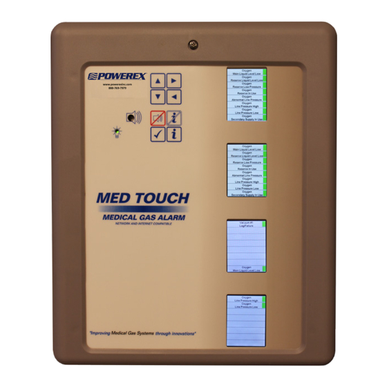
The Powerex Med Touch combination area and master alarm
panel digitally displays gas pressure (1 psi increments), monitors and
displays normal and alarm conditions from up to 128 remote medical
gas source signals, and provides alarm conditions as required by the
latest edition of NFPA 99 for up to 16 medical gases. The alarm is ETL
listed to UL 1069 and CSA C22.2 # 205 Signal equipment. Transducers
& DISS risers are included for area alarm gas boards. Transducers may
be installed remotely or in the back box. Pressure switches and DISS
union check valve connectors are sold separately.
Features & Benefits
• Five year parts and one year labor warranty
• 2.85" LCD touch screen displays up to 8 normal and alarm
conditions for pressure switch sensor inputs
• 2.85" LCD touch screen displays up to 8 normal and alarm
conditions and provides a digital pressure display for up to 4
transducer sensor inputs
• 2.85" LCD touch screen displays normal and high/low alarm
conditions for one 4 – 20 mA sensor input
• The LCD touch screen allows all alarm programming and set up to
be done without the use of tools
• A green normal or red alarm condition for each gas services
confirms the condition for each individual gas service
• Emergency preparedness instructions - Med Touch alarm panels
allow users to set up customized instructions for each alarm
signal, to appear on the screen when the signal is in alarm
• Up to 128 signal points in a single panel
• Wireless (minimal low voltage wiring) models available (wireless
feature for master signal points only)
• Last event history (per gas board /signal point)
• Made in the U.S.A.
• NFPA and ISO pre-loaded gas 'labels'
• English, and English/French pre-loaded languages
• Editable text and alarm 'labels'
• Self-contained unit - Designed for ease of installation and service
• Self-diagnostic and error message display for ease of maintenance
• Audio and visual alarm indicators
• Bright easy to read LCD displays – clearly visible in both day and
Powerex • 150 Production Drive • Harrison, OH 45030 • USA
P 1.888.769.7979 • F 513.367.3125 • www.powerexinc.com
Med Touch Series LCD Alarm Systems
Master Alarm
Combination Alarm
night lighting conditions
• Constant display and monitoring of each gas
• User programmable high/low set points on transducer and 4 – 20
mA sensor input boards
• Dry contacts provided on the CPU module for general fault
condition covering entire panel
• Hinged frame for easy accessibility
• Color coded displays
• Alarm history display of previous alarm conditions
• Hinged frame for easy accessibility
• Color coded labeling
• Wireless (minimal low voltage wiring) models available
Area Alarm
IN597400AV • 08/2016
Page 1 of 56
Advertisement
Table of Contents

Related Manuals for Powerex Med Touch Series


Summary of Contents for Powerex Med Touch Series
-
Page 1: Features & Benefits
• Wireless (minimal low voltage wiring) models available • Bright easy to read LCD displays – clearly visible in both day and Powerex • 150 Production Drive • Harrison, OH 45030 • USA IN597400AV • 08/2016 P 1.888.769.7979 • F 513.367.3125 • www.powerexinc.com... - Page 2 Modbus to BACnet gateway to interface to a BACnet building management system through Ethernet connectivity. Powerex • 150 Production Drive • Harrison, OH 45030 • USA IN597400AV • 08/2016 P 1.888.769.7979 • F 513.367.3125 • www.powerexinc.com Page 2 of 56...
-
Page 3: Table Of Contents
Programming the Board Com ID Programming the Gas Service (Area Alarm) Programming Language & Latching/Non-Latching Alarm Relays View Screen Powerex • 150 Production Drive • Harrison, OH 45030 • USA IN597400AV • 08/2016 P 1.888.769.7979 • F 513.367.3125 • www.powerexinc.com Page 3 of 56... -
Page 4: Introduction
NFPA 99 and CSA Z7396.1. specific, color coding (per NFPA 99 The Powerex gas alarm system is an assembly comprised of a rough- or CSA Z7396.1). The display shows in box, a front panel and transducers (if it is an area, combination or the actual gas pressure along with transducer master alarm). -
Page 5: Major Components
Rough-in or back box with power supply Front Panel with circuit boards Transducers Risers Powerex • 150 Production Drive • Harrison, OH 45030 • USA IN597400AV • 08/2016 P 1.888.769.7979 • F 513.367.3125 • www.powerexinc.com Page 5 of 56... -
Page 6: Alarm Installation
Side/end view of rough-in back box Powerex • 150 Production Drive • Harrison, OH 45030 • USA IN597400AV • 08/2016 P 1.888.769.7979 • F 513.367.3125 • www.powerexinc.com Page 6 of 56... -
Page 7: Plumbing The Riser Extension Tubes
Replace the power supply cover and plaster cover (to protect the unit while the drywall and wall covering work are being done) after wiring is complete. Powerex • 150 Production Drive • Harrison, OH 45030 • USA IN597400AV • 08/2016 P 1.888.769.7979 • F 513.367.3125 • www.powerexinc.com... -
Page 8: Installing The Hinges
(if necessary) front panel using the screws provided. Powerex • 150 Production Drive • Harrison, OH 45030 • USA IN597400AV • 08/2016 P 1.888.769.7979 • F 513.367.3125 • www.powerexinc.com... -
Page 9: Installing The Transducers (Non-Remote)
4”x 4”x 2 1/8” electrical junction box for added protection. wire polarities remain the same even if the wire colors are changed. Powerex • 150 Production Drive • Harrison, OH 45030 • USA IN597400AV • 08/2016 P 1.888.769.7979 • F 513.367.3125 • www.powerexinc.com... -
Page 10: Wiring The Remote Devices (Dry Contacts)
Note: it is required that polarity be maintained between the switch being monitored and the master alarm. Powerex • 150 Production Drive • Harrison, OH 45030 • USA IN597400AV • 08/2016 P 1.888.769.7979 • F 513.367.3125 • www.powerexinc.com... -
Page 11: Wiring The Remote Devices (Transducers)
The white wire from the transducer should be landed in the WHT position and the black wire from the transducer should be landed in the BLK position. Note: only Powerex D and T series alarm transducers are compatible with the Med Touch alarm system. -
Page 12: Wiring The Remote Devices (4-20Ma)
Land the 4-20mA signal wire to the Number 2 terminal port. Land the +12VDC wire to the Number 1 terminal port. Powerex • 150 Production Drive • Harrison, OH 45030 • USA IN597400AV • 08/2016 P 1.888.769.7979 • F 513.367.3125 • www.powerexinc.com... -
Page 13: Power On
The alarm is shown here with Medical Vacuum at normal operating pressures. All remote signal points (master alarm signals) are shown in normal condition. Powerex • 150 Production Drive • Harrison, OH 45030 • USA IN597400AV • 08/2016 P 1.888.769.7979 • F 513.367.3125 • www.powerexinc.com... -
Page 14: Alarm Displays & Functions
The right arrow may be pressed & held at any time to display the gas service for which the gas modules (area) boards are currently programmed. (See list on page 15). Powerex • 150 Production Drive • Harrison, OH 45030 • USA IN597400AV • 08/2016 P 1.888.769.7979 • F 513.367.3125 • www.powerexinc.com... -
Page 15: Gas Module (Area Alarms)
NFPA 99 at ± 20% of the normal operating pressure. Powerex • 150 Production Drive • Harrison, OH 45030 • USA IN597400AV • 08/2016 P 1.888.769.7979 • F 513.367.3125 • www.powerexinc.com... -
Page 16: Master Remote Signal (Dry Contacts)
NFPA 99 master alarm signals. You also have the option for 4mA of creating your own ‘label’. User-entered Text & E-text Powerex • 150 Production Drive • Harrison, OH 45030 • USA IN597400AV • 08/2016 P 1.888.769.7979 • F 513.367.3125 • www.powerexinc.com Page 16 of 56... -
Page 17: Alarm Operation
/ history log information indicators) the normal/abnormal status of the remote equipment connected to the alarm. All alarm panels are pre-programmed upon Powerex • 150 Production Drive • Harrison, OH 45030 • USA IN597400AV • 08/2016 P 1.888.769.7979 • F 513.367.3125 • www.powerexinc.com... -
Page 18: Bacnet Gateway Module
Powerex • 150 Production Drive • Harrison, OH 45030 • USA IN597400AV • 08/2016 P 1.888.769.7979 • F 513.367.3125 • www.powerexinc.com... -
Page 19: Programming High & Low Alarm Pressure Set Points
• touching the OK button • on the next screen touch Back • on the next screen touch Save. Powerex • 150 Production Drive • Harrison, OH 45030 • USA IN597400AV • 08/2016 P 1.888.769.7979 • F 513.367.3125 • www.powerexinc.com... -
Page 20: Programming The Repeater Delay
If you wish to slightly change the calibration (usually to match another alarm panel Powerex • 150 Production Drive • Harrison, OH 45030 • USA IN597400AV • 08/2016 P 1.888.769.7979 • F 513.367.3125 • www.powerexinc.com... -
Page 21: Programming The Gas Service (Area Alarm)
The Gas Type number is a code (see table below) which corresponds to the gas service which has been Powerex • 150 Production Drive • Harrison, OH 45030 • USA IN597400AV • 08/2016 P 1.888.769.7979 • F 513.367.3125 • www.powerexinc.com... -
Page 22: Programming Text & E-Text Gas (Area Alarm)
• on the next screen touch OK • on the next screen touch Back • on the next screen touch Save Powerex • 150 Production Drive • Harrison, OH 45030 • USA IN597400AV • 08/2016 P 1.888.769.7979 • F 513.367.3125 • www.powerexinc.com... -
Page 23: Programming The Units Of Measure
20 and 21. values that will trigger these alarms based on the units that are selected. Powerex • 150 Production Drive • Harrison, OH 45030 • USA IN597400AV • 08/2016 P 1.888.769.7979 • F 513.367.3125 • www.powerexinc.com... -
Page 24: Installing Ethernet/Rabbit Boards
See page 28 for more information. Powerex • 150 Production Drive • Harrison, OH 45030 • USA IN597400AV • 08/2016 P 1.888.769.7979 • F 513.367.3125 • www.powerexinc.com... -
Page 25: Create Receive Connector
“SMTP” (Simple Mail Transfer Protocol) is one of the most common ways of sending e-mail. SMTP is a simple text conversation across a TCP/ IP connection. The Email Server resides on port 587, and so, that is what the rabbit board SMTP _ PORT is currently defined. Powerex • 150 Production Drive • Harrison, OH 45030 • USA IN597400AV • 08/2016 P 1.888.769.7979 •... - Page 26 Med Touch Series LCD Alarm Systems Powerex • 150 Production Drive • Harrison, OH 45030 • USA IN597400AV • 08/2016 P 1.888.769.7979 • F 513.367.3125 • www.powerexinc.com Page 26 of 56...
-
Page 27: Programming The Ethernet/Rabbit Board
VCP Drivers – the first box is Windows* - Comments – click on set-up executable – than click on CDM21218_Setup.exe to install the drivers. Powerex • 150 Production Drive • Harrison, OH 45030 • USA IN597400AV • 08/2016 P 1.888.769.7979 • F 513.367.3125 • www.powerexinc.com... - Page 28 2. Leave the defaults of Parity= None, Data Bits = 8, and Stop Bits = 1 3. Select the port in use on the laptop 4. Click the Open button Powerex • 150 Production Drive • Harrison, OH 45030 • USA IN597400AV • 08/2016 P 1.888.769.7979 • F 513.367.3125 • www.powerexinc.com...
- Page 29 PDT (program date/time) – this command programs the date and time as it will be displayed on the website and recorded in the event log. PIP (program panel IP) – this command programs the rabbit board’s IP address. Powerex • 150 Production Drive • Harrison, OH 45030 • USA IN597400AV • 08/2016 P 1.888.769.7979 •...
-
Page 30: E-Mail & Text Notifications
PCx (program contact) – this command is used to program a contact to be notified where x is the contact number. The contact number(s) will be displayed on the event log. Up to five contacts may be programmed. See Appendix M for Text Message carriers access information. Powerex • 150 Production Drive • Harrison, OH 45030 • USA IN597400AV • 08/2016 P 1.888.769.7979 •... - Page 31 Below is an illustration of a simplified typical managed network at a facility. Both the Server’s IP address and Gateway address must be programmed into the Ethernet/rabbit board of any alarm panel desired to be connected to the internet. Powerex • 150 Production Drive • Harrison, OH 45030 • USA IN597400AV • 08/2016 P 1.888.769.7979 •...
-
Page 32: Rabbit Board Programing Commands
5 contacts total. 5. Use the show and test mail commands as necessary to check setups. Powerex • 150 Production Drive • Harrison, OH 45030 • USA IN597400AV • 08/2016 P 1.888.769.7979 • F 513.367.3125 • www.powerexinc.com Page 32 of 56... -
Page 33: Modbus Interface
IP address. It is recommended that the same panel name used when programming the rabbit board be used here to avoid confusion. This mapping is set up using the software chosen for the reverse proxy server. Powerex • 150 Production Drive • Harrison, OH 45030 • USA IN597400AV • 08/2016 P 1.888.769.7979 •... - Page 34 This event log will display up to 100 recent events with the most recent event on the top line and the oldest event on the bottom line. Powerex • 150 Production Drive • Harrison, OH 45030 • USA IN597400AV • 08/2016 P 1.888.769.7979 •...
-
Page 35: Bacnet Interface
1. Using the provided Ethernet crossover cable, connect the device to the PC. 2. Turn the power ON to the Alarm Panel and the PC. Powerex • 150 Production Drive • Harrison, OH 45030 • USA IN597400AV • 08/2016 P 1.888.769.7979 • F 513.367.3125 • www.powerexinc.com... - Page 36 CD-ROM and refer to the trouble shooting section and other applicable tools on the CD. Powerex • 150 Production Drive • Harrison, OH 45030 • USA IN597400AV • 08/2016 P 1.888.769.7979 • F 513.367.3125 • www.powerexinc.com...
- Page 37 Modbus Interface A complete Modbus map for the largest Powerex alarm panel is embedded in the rabbit board. An example of what the Modbus map looks like is shown below. The Board ID numbers in the left hand column refer to the boards COM ID numbers as explained on page 20. On the Modbus map, there is also an explanation of the values used within the map such as Board Type character 1 is a Gas Board or 2 is a Master Board etc.
- Page 38 7. To save changes and force the gateway back to running mode, click on the Reboot Now button and after 5 seconds hit the Refresh button. You should see the gateway appear in the Mode: Running. Powerex • 150 Production Drive • Harrison, OH 45030 • USA IN597400AV • 08/2016 P 1.888.769.7979 •...
-
Page 39: Appendix A Glossary Of Terms
The National Fire Protection Association is an association engaged in standards development. Powerex • 150 Production Drive • Harrison, OH 45030 • USA IN597400AV • 08/2016 P 1.888.769.7979 • F 513.367.3125 • www.powerexinc.com... -
Page 40: Appendix B Alarm Specifications
22.720W x 13.125H x 1.250D Transducers Housing dimensions 1.990W x 1.990H x 3.625 (Length including inlet fittings) Powerex • 150 Production Drive • Harrison, OH 45030 • USA IN597400AV • 08/2016 P 1.888.769.7979 • F 513.367.3125 • www.powerexinc.com Page 40 of 56... -
Page 41: Appendix C Master Signal Wire Log
Common Wire Color Remote Signals Signal Position # Remote Signal Label Signal Wire Color Common Wire Color Powerex • 150 Production Drive • Harrison, OH 45030 • USA IN597400AV • 08/2016 P 1.888.769.7979 • F 513.367.3125 • www.powerexinc.com Page 41 of 56... -
Page 42: Appendix D Master Alarm Signal Listing
Using the back double arrow will start at the bottom of the fourth column and progress backwards. Powerex • 150 Production Drive • Harrison, OH 45030 • USA IN597400AV • 08/2016 P 1.888.769.7979 •... -
Page 43: Appendix E Wiring Diagram (Ac & Dc)
Med Touch Series LCD Alarm Systems Appendix E Digital Alarm or Master Alarm Wiring Schematic Powerex • 150 Production Drive • Harrison, OH 45030 • USA IN597400AV • 08/2016 P 1.888.769.7979 • F 513.367.3125 • www.powerexinc.com Page 43 of 56... -
Page 44: Appendix F Wiring Diagram Area Alarm Remote Transducers
Med Touch Series LCD Alarm Systems Appendix F Remote Mounting of Digital/Touch Screen Alarm Transducers Powerex • 150 Production Drive • Harrison, OH 45030 • USA IN597400AV • 08/2016 P 1.888.769.7979 • F 513.367.3125 • www.powerexinc.com Page 44 of 56... -
Page 45: Appendix G Wiring Diagram (Master Equipment)
Med Touch Series LCD Alarm Systems Appendix G Wiring Schematic Equipment Wiring to Digital/Touch Screen Master Alarm Powerex • 150 Production Drive • Harrison, OH 45030 • USA IN597400AV • 08/2016 P 1.888.769.7979 • F 513.367.3125 • www.powerexinc.com Page 45 of 56... -
Page 46: Appendix H Wiring Diagram (Master Remote Transducer)
Med Touch Series LCD Alarm Systems Appendix H Remote Mounting of Digital/Touch Screen Master Alarm Transducer Powerex • 150 Production Drive • Harrison, OH 45030 • USA IN597400AV • 08/2016 P 1.888.769.7979 • F 513.367.3125 • www.powerexinc.com Page 46 of 56... -
Page 47: Appendix I Wiring Diagram Master 4-20Ma Signals
Med Touch Series LCD Alarm Systems Appendix I Equipment wiring to Digital/Touch Screen 4-20mA Master Alarm Powerex • 150 Production Drive • Harrison, OH 45030 • USA IN597400AV • 08/2016 P 1.888.769.7979 • F 513.367.3125 • www.powerexinc.com Page 47 of 56... -
Page 48: Appendix J Wiring Diagram Ethernet Communication
Med Touch Series LCD Alarm Systems Appendix J Digital/Touch Screen Alarm Ethernet Ribbon Cable Connection Diagram Powerex • 150 Production Drive • Harrison, OH 45030 • USA IN597400AV • 08/2016 P 1.888.769.7979 • F 513.367.3125 • www.powerexinc.com Page 48 of 56... -
Page 49: Appendix K Wiring Diagram (Ac And Dc) Bacnet
Med Touch Series LCD Alarm Systems Appendix K Electrical Wiring Schematic with BACnet Interface Powerex • 150 Production Drive • Harrison, OH 45030 • USA IN597400AV • 08/2016 P 1.888.769.7979 • F 513.367.3125 • www.powerexinc.com Page 49 of 56... -
Page 50: Appendix L Wiring Diagram Bacnet Communication
Med Touch Series LCD Alarm Systems Appendix L Ethernet Ribbon Cable and BACnet Connection Diagram Powerex • 150 Production Drive • Harrison, OH 45030 • USA IN597400AV • 08/2016 P 1.888.769.7979 • F 513.367.3125 • www.powerexinc.com Page 50 of 56... -
Page 51: Appendix M Text Message Carriers
Med Touch Series LCD Alarm Systems Appendix M Text Message Carriers char Carriers[SMS_MAX_CARRIERS][2][64] = { Powerex • 150 Production Drive • Harrison, OH 45030 • USA IN597400AV • 08/2016 P 1.888.769.7979 • F 513.367.3125 • www.powerexinc.com Page 51 of 56... - Page 52 Med Touch Series LCD Alarm Systems Powerex • 150 Production Drive • Harrison, OH 45030 • USA IN597400AV • 08/2016 P 1.888.769.7979 • F 513.367.3125 • www.powerexinc.com Page 52 of 56...
- Page 53 Med Touch Series LCD Alarm Systems Powerex • 150 Production Drive • Harrison, OH 45030 • USA IN597400AV • 08/2016 P 1.888.769.7979 • F 513.367.3125 • www.powerexinc.com Page 53 of 56...
-
Page 54: Appendix N Ethernet/Rabbit Board Programming Log
(PMI) Program SMTP Mail Server IP (PUN) Program User Name (PUP) Program User Password (PCX) Program Contacts for Alarm Panel Powerex • 150 Production Drive • Harrison, OH 45030 • USA IN597400AV • 08/2016 P 1.888.769.7979 • F 513.367.3125 • www.powerexinc.com Page 54 of 56... - Page 55 Powerex within twelve (12) months from date of shipment to Buyer, that the product is found by Powerex to have been defective at the time of such shipment, that the product has been installed and/or operated in accordance with Powerex’s instructions, that no repairs, alterations or replacements have been made by others without Powerex’s...
-
Page 56: Terms & Warranty
Buyer. Powerex shall not, except as set forth above, be otherwise liable to Buyer or to any person who shall purchase from Buyer, or use, any products supplied hereunder for damages of any kind, including, but not limited to, indirect, special or consequential damages or loss of production of loss of profits resulting from any cause whatsoever, including, but not limited to, any delay, act, error or omission of Powerex.
Need help?
Do you have a question about the Med Touch Series and is the answer not in the manual?
Questions and answers