Table of Contents
Advertisement
Quick Links
KSZ8851SNL
32-pin Single-Port Ethernet Controller
With Serial Peripheral Interface (SPI)
Evaluation Board User's Guide
Revision 1.1
April 2010
© Micrel, Inc. 2007
All rights reserved
Micrel is a registered trademark of Micrel and its subsidiaries in the
United States and certain other countries. All other trademarks are the
property of their respective owners.
The information furnished by Micrel in this datasheet is believed to be accurate and reliable. However, no responsibility is
assumed by Micrel for its use. Micrel reserves the right to change circuitry and specifications at any time without
notification to the customer. Micrel Products are not designed or authorized for use as components in life support
appliances, devices or systems where malfunction of a product can reasonably be expected to result in personal injury.
Life support devices or systems are devices or systems that (a) are intended for surgical implant into the body or (b)
support or sustain life, and whose failure to perform can be reasonably expected to result in a significant injury to the user.
Micrel, Inc. ♦ 2180 Fortune Drive ♦ San Jose, CA 95131 ♦ U.S.A.
408-944-0800 (voice) ♦ 408-474-1000 (fax)
http://www.Micrel.com
Advertisement
Table of Contents

Related Manuals for Micrel KSZ8851SNL-Eval


Summary of Contents for Micrel KSZ8851SNL-Eval
- Page 1 The information furnished by Micrel in this datasheet is believed to be accurate and reliable. However, no responsibility is assumed by Micrel for its use. Micrel reserves the right to change circuitry and specifications at any time without notification to the customer.
- Page 2 KSZ8851SNL-Eval Evaluation Board User’s Guide A Purchaser's use or sale of Micrel Products for use in life support appliances, devices or systems is at Purchaser's own risk and Purchaser agrees to fully indemnify Micrel for any damages resulting from such use or sale.
-
Page 3: Table Of Contents
Rev. 1.1 KSZ8851SNL-Eval Evaluation Board User’s Guide Table of Contents Introduction ................5 Board Features............... 5 Evaluation Kit Contents............5 Hardware Description ............6 Host SPI Interface ....................7 Jumper Setting & Definition .................. 8 Power Supply and Test Point Definition .............. 9 RJ-45 Connector and Transformer ............... - Page 4 Figure 1. KSZ8851SNL Evaluation Board ..................6 Figure 2. SPI Interface to KSZ8851SNL ..................7 Figure 3. KSZ8851SNL-Eval Host SPI Interface Connection with Spirent SmartBits..... 7 List of Tables Table 1. Header JP1 – Host Connection for SPI Interface.............. 8 Table 2.
-
Page 5: Introduction
Rev. 1.1 KSZ8851SNL-Eval Evaluation Board User’s Guide Introduction The KSZ8851SNL-Eval Evaluation Board is intended to provide a convenient and fast way to evaluate or demonstrate the functionality and performance of this new Single-Port Ethernet Controller KSZ8851SNL device from Micrel. The KSZ8851SNL comes with a 32-pin, lead-free QFN (5mm x 5mm) package and provides an ideal solution for applications requiring Serial Peripheral Interface (SPI) between single-port Ethernet Controller and Host microcontroller. -
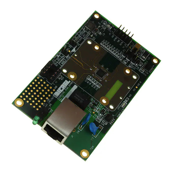
Page 6: Hardware Description
KSZ8851SNL-Eval Evaluation Board User’s Guide Hardware Description The KSZ8851SNL-Eval (shown in Figure 1) comes in a compact form factor and plugs directly into industry standard test equipment such as Spirent SmartBits, the other side of board is wired to external host SPI interface through headers. Configuration of the KSZ8851SNL is accomplished through on-board jumper selections and/or by register access via the host SPI Interface. -
Page 7: Host Spi Interface
SPI interface connection for KSZ8851SNL. Figure 2. SPI Interface to KSZ8851SNL The KSZ8851SNL-Eval board receives +5V power from the header JP1 (pin 1). Figure 3 shows the Host SPI interface connection with Spirent SmartBits for system set-up and performance test. -
Page 8: Jumper Setting & Definition
Table 2. Header JP1 – Host Connection for Control and Power 4.2 Jumper Setting & Definition The KSZ8851SNL-Eval does not require any jumper for normal operation except the VDD_IO option. During power-up, the KSZ8851SNL is configured using the chip’s internal pull-up and pull- down resistors with its default strapping pin value which will set this device in operation of without EEPROM. -
Page 9: Power Supply And Test Point Definition
The KSZ8851SNL-Eval is supplied from external +5.0V DC power through a Header (pin 1 at JP1), this +5.0V DC input is converted to both +3.3V with a Micrel LDO voltage regulator (U3, MIC5209BM) for 3.3VA analog power and VDD (option for 3.3V, 2.5V or 1.8V) with a Micrel LDO voltage regulator (U4, MIC5209BM) for VDD_IO digital power. -
Page 10: Board Reset
Table 7. KSZ8851SNL-Eval LED Definition 4.6 Board Reset The KSZ8851SNL-Eval generates a reset signal from the reset circuitry during power up. It also provides a push button S1 reset circuit to reset the KSZ8851SNL device. During power up, the board is automatically reset. User can also press reset button S1 on the board for a manual reset. -
Page 11: Bill Of Materials
Rev. 1.1 KSZ8851SNL-Eval Evaluation Board User’s Guide Bill of Materials KSZ8851SNL Eval Board (Revision 1.1) Micrel, Inc. April 21, 2010 11/11...
Need help?
Do you have a question about the KSZ8851SNL-Eval and is the answer not in the manual?
Questions and answers