Subscribe to Our Youtube Channel
Summary of Contents for Micrel KSZ8463ML
- Page 1 KSZ8463_eval_bd_user_guide_1.1.docx KSZ8463ML/RL Evaluation Board User Guide Preliminary Revision 1.1 / July 17, 2013 Micrel, Inc. July 17, 2013 Confidential Rev. 1.1 1/16...
-
Page 2: Table Of Contents
Table 4 MII Port Configuration Settings ..................... 10 Table 5 RMII Clock Setting ........................10 Table 6 RMII Signal Description ........................ 10 Table 7 GPIO pin selection for KSZ8463ML ..................... 11 Table 8 LED Functions ..........................13 Table 9 List of Jumpers and Connectors ....................14 Micrel, Inc. -
Page 3: Introduction
RMII mode. This KSZ8463ML/RL Evaluation Board User Guide provides the information necessary to configure and set up the board to evaluate or test the KSZ8463ML and KSZ8463RL devices in different environments. 1 Board Features The KSZ8463ML/RL Evaluation Board encompasses the following features. -
Page 4: Ksz8463Ml/Rl Evaluation Board Kit
3-port switch. The KSZ8463ML/RL has a serial interface which can be either SPI or MIIM (MDIO/MDC). Normally the SPI interface is used because it provides read/write access to all KSZ8463 registers. In comparison, the MIIM interface provides access only to the basic PHY registers in the KSZ8463. -
Page 5: Configuration Options
Note that even if no external strap-in jumpers are set, internal pull-up and pull-down resistors will set the KSZ8463ML/RL to the default configuration. The following table covers each jumper used for the strap-in option and describes its function. -
Page 6: Usb Interface (Spi Slave Or Mdio)
3.1.2 USB Interface (SPI Slave or MDIO) With the Micrel utility software that runs on a PC, it is possible to access the full register set of the device through the USB port provided on the evaluation board. Download and install the Windows based... -
Page 7: Port 3 Configuration
KSZ8463ML/FML must be set to PHY mode. The KSZ8463ML/FML provides a bypass feature in the MII PHY mode. JP27 is used to enable the MII bypass mode. In the bypass mode, MII (port 3) is shut down and no new ingress frames from either Port 1 or Port 2 will be sent out through Port 3. -
Page 8: Mii Port Configuration (Ksz8463Ml, Ksz8463Fml)
The Media Independent Interface (MII) is specified in Clause 22 of the IEEE 802.3 standard. It provides a common interface between PHY layer and MAC layer devices. The MII provided by the KSZ8463ML/FML is connected to the device’s third MAC (Port 3). The interface contains two distinct groups of signals, one for transmission and the other for reception. -
Page 9: Rmii Port Configuration (Ksz8463Rl And Ksz8463Frl)
KSZ8463ML/FML. So, for PHY mode operation, if the device interfacing with the KSZ8463ML/FML has an RX_ER input pin, it needs to be tied low. And, for MAC mode operation, if the device interfacing with the KSZ8463ML/FML has a TX_ER input pin, it also needs to be tied low. -
Page 10: Table 4 Mii Port Configuration Settings
Input Output TXD0 Transmit data bit 0 Input Output TP16 TXD1 Transmit data bit 1 Input Output TP15 RX_ER Receive error Output Input or not required Table 6 RMII Signal Description Micrel, Inc. July 17, 2013 Confidential Rev. 1.1 10/16... -
Page 11: Gpio Pins
For the KSZ8463RL device, pins 1 and 2 of all three jumpers need to be closed in order to make GPIO7, 9 and 10 available at the GPIO headers. In case of KSZ8463ML, GPIO7, 9 and 10 are Port1/2 LED activity signals by default and no strapping is needed. -
Page 12: 10/100 Ethernet Phy Ports
Figure 3 GPIO Connectors and Related Jumper Locations 3.5 10/100 Ethernet PHY Ports There are two 10/100 Ethernet PHY ports on the KSZ8463ML/RL evaluation board. The ports can be connected to an Ethernet traffic generator or analyzer via standard RJ-45 connectors using CAT-5 (or better) UTP cables. -
Page 13: Led Indicators
PxLED0 = Link Table 8 LED Functions The KSZ8463ML/RL evaluation board also has a power LED (D3) for the 3.3V power supply. When D3 is illuminated, the board’s 3.3V power supply is “on”. The activity LED indicators for Port-1 and Port-2 are powered by VDD_IO, which can be set to 3.3V, 2.5V or 1.8V. -
Page 14: List Of Jumpers And Connectors
SPI interface JP36-38 GPIO7, GPIO9 and GPIO10 pin source Pins 1-2 closed for KSZ8463RL/FRL selection on GPIO Headers Pins 2-3 closed for KSZ8463ML/FML JP77, 78 FXSD1, FXSD2 Fiber signal detect input for Port 1 and Port 2 (not used) JP79... -
Page 15: Board Layout
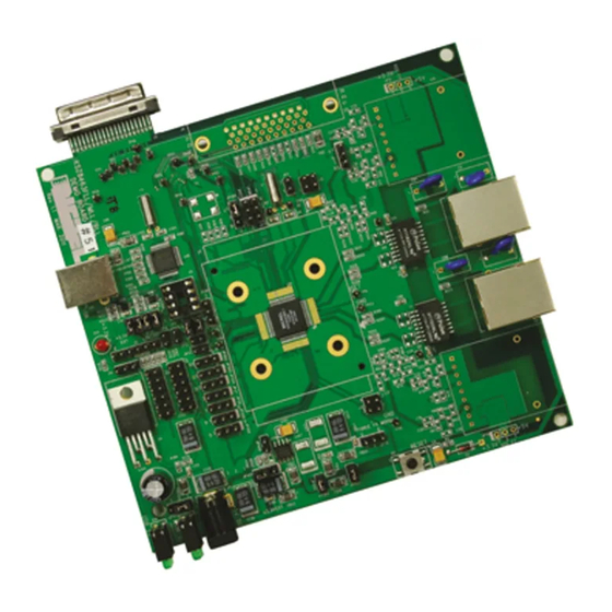
The layout of the board is shown in Figure 3. The key areas are indicated. Figure 4 Topside Layout of the Board The KSZ8463ML/RL Evaluation board, together with the KSZ9692PB SOC board (KSZ9692-MII-PTP-EV), provides a complete evaluation platform for the IEEE1588 PTP functionality. In this setup, Port 3 of the KSZ8463 evaluation board is configured in PHY mode and connected to the SOC board through its MII port. -
Page 16: Reference Documents
© Micrel, Inc. 2013 All rights reserved Micrel is a registered trademark of Micrel and its subsidiaries in the United States and certain other countries. All other trademarks are the property of their respective owners. The information furnished by Micrel in this datasheet is believed to be accurate and reliable. However, no responsibility is assumed by Micrel for its use.


Need help?
Do you have a question about the KSZ8463ML and is the answer not in the manual?
Questions and answers