Advertisement
Quick Links
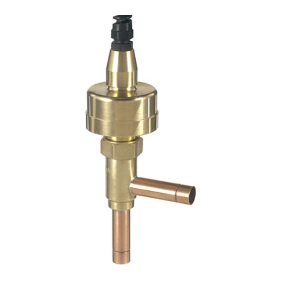
SYSTEM CONSIDERATIONS
The discharge bypass valve is applied in a branch line off
the discharge line as close to the compressor as possible.
The bypassed vapor can enter the low side at one of the fol-
lowing locations:
1. Evaporator inlet with distributor.
2. Evaporator inlet without distributor.
3. Suction line.
Each is illustrated and discussed below.
BYPASS TO EVAPORATOR INLET
WITH DISTRIBUTOR
This method of application, illustrated in Figure 1, offers
distinct advantages over the other methods, especially for
unitary or field built-up units where the high and low side
are close coupled. The primary advantage of this method is
that The EDBV can directly control the temperature of the
cooled fluid. A sensor placed in the air off the evaporator or
on the chilled water line of a chiller can cause the EDBV to
modulate to maintain the desired temperature. In addition,
the system thermostatic expansion valve will respond to the
increased superheat of the vapor leaving the evaporator and
will provide the liquid required for desuperheating. The
evaporator serves as an excellent mixing chamber for the
bypassed hot gas and the liquid-vapor mixture from the
expansion valve. This ensures a dry vapor reaching the
compressor. Oil return from the evaporator is also improved
since the velocity in the evaporator is kept high by the hot
gas. Piping for this method of application can be accom-
plished by the use of a Sporlan 1650R series distributor on
a new application, or a Sporlan Auxiliary Side Connector
(ASC) when adding the valve to a system with distributor.
NOTE: If the distributor circuits are sized properly
for normal cooling duty, the flow of hot gas
ELECTRIC
DISCHARGE
Installation and Service Instructions
SDR-3 and SDR-4
through the circuits may cause excessive pressure
drop and/or noise. Therefore, it is recommended
that the distributor circuits be selected one size
larger than for straight cooling duty. For complete
technical details on the 1650R series distributor
and the ASC series Auxiliary Side Connector, refer
to Bulletin 20-10.
External Equalizer
Distributor
Evaporator
Return Air
SDR 4
Compressor
VALVE / EQUIPMENT LOCATION
AND PIPING
When the evaporator is located below the compressor on a
remote system, bypass to the evaporator inlet is still the
best method of hot gas bypass to insure good oil return to
the compressor. When this is done, the bypass valve must
be located at the compressor rather than at the evaporator
section. This will insure obtaining rated capacity from
the bypass valve at the conditions for which it was
selected. If the evaporator is above or on the
same level as the compressor, this valve
location will also eliminate the possibility
of hot gas condensing in the long
bypass line and running back into
the compressor during the off
cycle. Whenever hot gas
bypass to the evaporator
inlet is necessary for a
system with two or
more evaporator
BYPASS
VALVES
Figure 1
TEV
Solenoid
Valve
TCB
Condenser
Receiver
®
See•All
Catch-All
Advertisement

Related Manuals for Sporlan SDR-4


Summary of Contents for Sporlan SDR-4
- Page 1 Piping for this method of application can be accom- bypass line and running back into plished by the use of a Sporlan 1650R series distributor on the compressor during the off a new application, or a Sporlan Auxiliary Side Connector cycle.
- Page 2 This type of application provides the 65°F, contact Sporlan Valve Company or the compressor man- same advantages as bypassing hot gas to the evaporator inlet ufacturer for assistance. In all cases the maximum per- with a distributor.
- Page 3 Page 3 CAUTION - Regardless of whether the valve is in SDR-4 Figure 5 the system or in a vise, care must be take to pre- vent distorting the valve parts when tightening. 4. The motor assembly may be removed for inspection and cleaning.
- Page 4 MOTOR ACTUATOR should be taken to prevent the splice from lying in a wet location. 1. Connect any Sporlan step motor valve to the SMA-12 by matching wire color to terminal color. Any 12 VDC bipo- VALVE REPLACEMENT lar step motor may be tested with the SMA-12. Phase one leads should be connected to the black and white termi- The entire valve may be replaced if desired.
Need help?
Do you have a question about the SDR-4 and is the answer not in the manual?
Questions and answers