Table of Contents
Advertisement
Quick Links
SD-68-52016
INSTALLATION & SERVICE INSTRUCTIONS
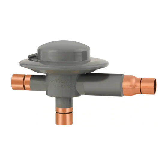
Head Pressure Control Valves
OROA-5, ORI-6-65/225H, ORI-10-65/225-H, ORD-4
INSTALLATION INSTRUCTIONS
To ensure proper performance, head pressure control valves
must be selected and applied correctly. This is covered thor-
oughly in Bulletin 90-30. However, proper installation proce-
dures are equally important.
VALVE LOCATION/PIPING SUGGESTIONS — The
OROA, ORI and ORD valves can be installed in horizontal
or vertical lines – whichever best suits the application, and
permits easy accessibility of all valves. Consideration should
be given to locating these valves so they do not act as an oil
trap and so solder cannot run into the internal parts during
brazing. Precautions should also be taken to install the valves
with the flow in the proper direction.
The ORI valve CANNOT be installed in the discharge
line for any reason.
Figures 1 and 2 are piping schematics only to illustrate the
general location of the OROA, ORI, and ORD valves in
the system. Sporlan recommends that recognized piping
references be consulted for assistance in piping procedures.
Sporlan is not responsible for system design, or for misap-
plication of its products. If these valves are applied in any
manner other than described in this bulletin, the Sporlan
warranty is void.
In most cases, the valves are located at the condensing unit.
When the condenser is remote from the compressor, the usual
location is near the compressor. In all cases, it is important
that some precautions be taken in mounting the valves. It is
suggested that they be adequately supported to prevent exces-
sive stress on the connections. Discharge lines are a possible
Figure 1
Condenser
ORD-4
Compressor
Figure 2
OROA
Compressor
ORI
Receiver
Condenser
Receiver
© Copyright 2016 by Sporlan Division, Parker Hannifin, Washington, MO
FOR USE ON REFRIGERATION and/or AIR CONDITIONING SYSTEMS ONLY
source of vibrations and gas pulsations, which may result in
fatigue in tubing, fittings, and connections. The severity of
discharge gas pulses differs with each system. On some appli-
cations it may be necessary to dampen the pulses to protect
the ORD-4 internal parts. Pulsations are best handled by a
good muffler placed as close to the compressor as possible.
Vibrations from moving parts of the compressor are best
isolated by flexible loops or coils (discharge lines 1/2" or
smaller), or flexible metal hoses for larger lines.
For best results, the hoses should be installed as close to
the compressor shut-off valves as possible, and mounted
horizontal and parallel to the crankshaft or vertically upward.
The hoses should never be mounted horizontal and 90° from
the crankshaft. A rigid brace should be placed on the outlet
end of the hose to prevent vibrations beyond the hose.
The inlet connections on the OROA-5, ORI-6 and ORI-10
valves should be sized the same as the outlet of the condenser
where possible. The ORD-4 is available with 5/8" ODF and
7/8" ODF solder connections. On systems with discharge
lines smaller than 5/8" OD, the bypass line can be the same
size as the discharge line and the ORD-4 connections can be
bushed down. If the system capacity is greater than any of
the head pressure control valves ratings, these valves can be
applied in parallel.
CAUTION: When the head pressure control valves are fac-
tory installed and capped for future hook-up in the field, any
holding charge in the condensing unit and valve assembly
should be bled off from all sides of the valves before remov-
ing the caps. This will prevent the caps from blowing off due
to any trapped refrigerant.
VALVE STRAINERS – Catch-All
See·All
moisture and liquid indicator — Just as with
®
any refrigerant flow control device, the need for an inlet
strainer is a function of system cleanliness and proper instal-
lation procedures. When the strainer is used with the ORI,
the tubing is inserted in the valve connection until the tubing
and strainer flange ring are up against the tubing stop, thus
locking the strainer in place. See Figure 3. In order for the
strainer to seat properly against the tubing stop of the OROA
condenser connection, the strainer is inserted into the tubing.
The tubing is then inserted into the valve connection, thus
locking the strainer in place. See Figure 4.
Figure 3
Tubing
Tubing
Figure 4
Strainer
filter-driers –
®
Tubing Stop
Valve Connection ORI
Strainer
Tubing Stop
Valve Connection OROA
Advertisement
Table of Contents

Related Manuals for Sporlan OROA-5


Summary of Contents for Sporlan OROA-5
- Page 1 The inlet connections on the OROA-5, ORI-6 and ORI-10 Figures 1 and 2 are piping schematics only to illustrate the valves should be sized the same as the outlet of the condenser general location of the OROA, ORI, and ORD valves in where possible.
- Page 2 Page 2 Moisture and particles too small for the inlet strainer are harm- The ORD-4-20 setting means that the ORD-4 will start to ful to the system and must also be removed. Therefore, for open when the pressure difference between the discharge complete system protection, it is recommended that a Catch- line and the receiver is 20 psig.
- Page 3 Pounds @ -20°F These calculations do not take into account cylinder unload- and Thickness Each Refrigerant ing. Additional charge will be required. For more complete Inches Return charging recommendations, see Sporlan Bulletin 90-30-1. Bend-Feet .016 .060 .055 .057 .017 .110 .102...
- Page 4 2. Do not overcharge — see charge and charging Component Selection and Receiver - psi procedures on pages 2 and 3. OROA-5-100 or -180 3. Be sure that the piping does not allow liquid Below 14 ORD-4-20 & ORI refrigerant to be trapped in sections where *OROAB-5-100 or -180 hydrostatic pressure can develop.
Need help?
Do you have a question about the OROA-5 and is the answer not in the manual?
Questions and answers