
Related Manuals for ESP EnVision EV-12010 BR

Summary of Contents for ESP EnVision EV-12010 BR
- Page 1 User Manual 120 and 208-240 Volt Models © 2019 AMETEK Electronic Systems Protection / Technical Support: 1-800-645-9721 / ametekesp.com / UM-enVision-Rev-H...
- Page 2 User Manual © 2019 AMETEK Electronic Systems Protection / Technical Support: 1-800-645-9721 / ametekesp.com...
-
Page 3: Table Of Contents
User Manual I. PRODUCT OVERVIEW......................4 1. M ........................... 4 ODELS 2. K ......................... 4 EATURES 3. T ......................4 ECHNICAL UPPORT II. INSTALLATION INSTRUCTIONS ..................5 1. F ......................5 ILTER NSTALLATION a. T ....................5 URN OFF EQUIPMENT b. - Page 4 User Manual V. USING THE SOFTWARE ....................14 1. P ....................14 HYSICAL ONNECTIONS 2. S ....................14 TART THE OFTWARE 3. C COM P ..........15 ONFIGURE THE NTERFACE ABLE AND 4. S ......................17 OFTWARE ODES a. M ....................
-
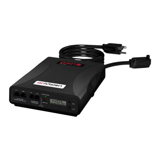
Page 5: Product Overview
(detailed in Diagnostic Software User Manual) 3. Technical Support: • To download software and access further product information, visit www.ametekesp.com • For enVision PCS technical support, please contact ESP at 1-800-645-9721 © 2019 AMETEK Electronic Systems Protection / Technical Support: 1-800-645-9721 / ametekesp.com... -
Page 6: Installation Instructions
User Manual INSTALLATION INSTRUCTIONS 1. Filter Installation a. Turn off the machine you are connecting to the Filter, and unplug the machine’s power cord from wall outlet. Éteignez la machine que vous connectez au filtre et débranchez de la prise murale le cordon d'alimentation de la machine. -
Page 7: Connect Equipment
User Manual d. Connect Equipment i. Make sure that the total amperage of all equipment plugged into the Filter does not exceed the maximum branch circuit rating. Assurez-vous que l'intensité totale de tous les appareils reliés au filtre ne dépasse pas la tension maximale du circuit de dérivation. Asegúrese de que el amperaje total del equipo conectado al filtro no supere la clasificación máxima del circuito de derivación. -
Page 8: Connect Filter To Outlet
You may also need to verify that the Filter is operating properly. To test, plug the Filter into a known properly functioning outlet. If the “System On” LED still does not illuminate in the functioning outlet, contact ESP at 1-800- 645-9721. -
Page 9: Hardware
User Manual III. HARDWARE 1. Filter a. LCD Event Monitor The LCD EVENT MONITOR displays useful information related to data collection, device status, and troubleshooting. i. Normal Operation When the EnVision PCS Filter is plugged into a branch circuit outlet with correct wiring and acceptable line voltage, the LCD Event Monitor will display the following information: Menu Item... - Page 10 User Manual Power Power Outages Disturbances (Pd) Under Voltages (Off) Under Voltages (Record) Over Voltages (Record) Over Voltages (Off) Surges Overload Last Recorded Event Outlet State (OS) On / Off User Control Turn Outlets On / Off (UC) Press and hold Memory All Clear (ALC) Menu and Scroll buttons to...
-
Page 11: Wiring Fault
User Manual Wiring Fault When connected to an incorrectly wired branch circuit outlet, in addition to the illumination of the Red LED, the LCD Event Monitor will display the following information: Wiring Fault Condition Display Example Display Line (Hot) / Neutral rP (Reverse Reversed Polarity) -
Page 12: Clearing Memory
User Manual b. Clearing Memory: The memory contents of the Filter can be cleared at any time by following one of these two methods: Buttons: Follow these steps to clear the device memory: Press the Menu button until “UC” (User Control) is displayed. Next, press the Scroll Button to select which memory record to erase: Memory All Clear (ALC) -
Page 13: Data Interface Cable
User Manual 2. Data Interface Cable a. Overview The Data Interface Cable consists of a USB connection on one end, and a RJ-11 connection on the opposite end. The USB connection plugs into an available USB port on your PC. The RJ-11 connection plugs into the RJ- 11 “OUT”... -
Page 14: Software Installation
App. It can also be downloaded directly at https://play.google.com/store/apps/details?id=com.espsurgex.envison. Requires USB OTG (On The Go) adapter, Android device with USB OTG support, and ESP USB interface cable (XG-PCS-IC-1) © 2019 AMETEK Electronic Systems Protection / Technical Support: 1-800-645-9721 / ametekesp.com... -
Page 15: Install Data Interface Cable
2. Start the Software a. Double-click the desktop shortcut labeled “ESP SurgeX Diagnostic Tool”, or use the “ESP SurgeX Diagnostic Tool” Start Menu shortcut located at: Start/All Programs/ESP SurgeX/Diagnostic Tool © 2019 AMETEK Electronic Systems Protection / Technical Support: 1-800-645-9721 / ametekesp.com... -
Page 16: Configure The Data Interface Cable And Com Port
User Manual 3. Configure the Data Interface Cable and COM Port a. Click the COM Port Setup button labeled COM. b. Click Configure. The auto configuration process will automatically set the correct device parameters of the Data Interface Cable to operate properly with the software and enVision. - Page 17 User Manual The COM port may also be manually configured using the Device Manager: 1. Open Device Manager a. Click on Start button b. Type the following command in the Search box: devmgmt.msc c. Press Enter 2. In the Device Manager, expand “Ports (COM & LPT)” 3.
-
Page 18: Software Modes
User Manual c. Click Detect. The auto detect process will automatically detect the COM Port number assigned to the Data Interface Cable . ii. If the auto detection process is successful, click Save. The software is now properly configured and ready for use. iii. -
Page 19: Multimeter Mode
User Manual a. Multimeter Mode The Multimeter Mode provides information traditionally acquired from one or more handheld digital multimeters, as well as an overview of the recorded power quality events and energy consumption of connected equipment. ±2% Measurement Accuracy. © 2019 AMETEK Electronic Systems Protection / Technical Support: 1-800-645-9721 / ametekesp.com... -
Page 20: Scope Mode
User Manual ii. Real-time display of 8 electrical parameters • Line Voltage: AC RMS Volts Line-Neutral (Line1-Line2) Load Current Draw: AC RMS Amps • • Load Power Draw: Watts • Neutral-Ground Voltage: AC RMS Volts Neutral-Ground (Line2- Ground) Line Frequency: Hertz •... - Page 21 User Manual iii. Up ▲ and Down ▼ Arrow buttons adjust the vertical axis scaling of each channel. iv. Left ◄ and Right ► Arrow buttons adjust the horizontal (time) axis scaling. v. While in normal operation, pressing the Wait button will freeze the currently displayed waveform.
-
Page 22: Chart Mode
User Manual c. Chart Mode The Chart Mode enables a chart style data logging function of 8 electrical parameters. Data point measurements are acquired once per second. The measured parameters may be enabled or disabled by pressing the corresponding button. ii. -
Page 23: Outlet Control Mode
User Manual d. Outlet Control Mode The Outlet Control Mode enables control of the AC outlets and provides information about wiring faults and abnormal line voltage. ii. Use the green On/Off button to manually turn the AC outlets on and off. Pressing the blue Power Cycle button will result in the execution •... -
Page 24: Historical Data Mode
User Manual e. Historical Data Mode The Historical Data Mode allows for the retrieval and display of the power quality event and electrical parameter data stored in the enVision internal memory. Time Stamped Power Quality Event Data ▪ enVision is able to store and timestamp the 512 most recent power quality events in its internal memory. - Page 25 User Manual Twelve types of events are logged: ▪ Overload: Load current draw has exceeded 25A ▪ Surge: enVision has been exposed to a transient voltage in one of the 3 possible modes (between Live and Neutral, between Live and Ground, between Neutral and Ground) with a peak amplitude of 500V* or higher and a frequency of 20 kHz or higher.
- Page 26 User Manual ii. Historical Electrical Parameter Data Every 30 minutes, enVision stores a snapshot of 6 electrical parameters measured over the prior 30 minute interval. The internal memory can store 138 days of data. Press the Import Historical Data button to download the data.
- Page 27 User Manual 1. Average Power Graph Pressing the Average Power Graph button will display a bar graph of the average real power draw of connected equipment during each 30 minute recording interval. 2. Average Voltage Graph Pressing the Average Voltage Graph button will display a bar graph of the average line voltage during each 30 minute recording interval.
- Page 28 User Manual 3. Max/Min Graph Pressing the Max/Min Graph button will display line graphs of maximum voltage, minimum voltage, maximum current draw, and maximum power draw during each 30 minute recording interval. Pressing the V Max, V Min, I Max, or P Max buttons will enable or disable the display of the corresponding parameter.
-
Page 29: Settings Mode
User Manual iv. Import Data Previously saved data files may be imported by entering the Historical Data Mode while no enVision product is connected. This may be achieved by removing the data interface cable or by selecting and saving an invalid COM Port number. Press the button that corresponds to the type of data file to import and browse to the location of the file. - Page 30 User Manual i. Auto Set Clock: Automatically sets the internal clock to the current date and time. ii. Set Clock: Sets the internal clock to a date and time manually specified in the date/time field. iii. Auto Transmit: Enables/Disables the automatic transmission of status information every 30 minutes.
-
Page 31: Com Port Setup Mode
User Manual g. COM Port Setup Mode i. The COM Port Setup mode is used to configure new Data Interface Cables for use. ii. Detect: Automatically detect the COM Port when the enVision, Data Interface Cable, and PC are properly connected and powered iii. -
Page 32: Troubleshooting
Contact a licensed electrician to troubleshoot the wall receptacle. Use the Diagnostic Software to manually turn the outlets On. Defective product. Contact ESP for product replacement at Red LED Off, 800.645.9721. Green LED On, No power at output. -
Page 33: Specifications
User Manual VII. SPECIFICATIONS Parameter Specification Load Rating EV-12010 BR 10 Amps at 120 Volts EV-12015 15 Amps at 120 Volts EV-12016 BR 16 Amps at 120 Volts EV-12020 20 Amps at 120 Volts EV-20815 15 Amps at 208-240 Volts EV-20816 BR 16 Amps at 208-240 Volts EV-20820... - Page 34 User Manual Parameter Specification Under-Voltage 120V Models Adjustable from 0 V to 110 V. Default 80 V. Shutdown 208-240V Models Adjustable from 0 V to 220 V. Default 160 V. Under-Voltage Record 120V Models Adjustable from 0 V to 110 V. Default 100 V. 208-240V Models Adjustable from 0 V to 220 V.
Need help?
Do you have a question about the EnVision EV-12010 BR and is the answer not in the manual?
Questions and answers