Table of Contents
Advertisement
Quick Links
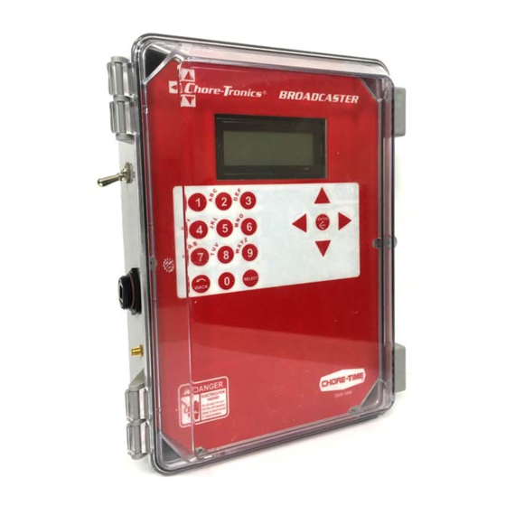
Broadcaster
Installation and Operators
Instruction Manual
Contact your nearby Chore-Time distributor or representative for additional parts and information.
Chore-Time Group
A division of CTB, Inc.
PO Box 2000
Milford, Indiana 46542-2000 USA
Phone (574) 658-4101 Fax (877) 730-8825
E-mail: www.choretimepoultry.com
Internet: poultry@choretime.com
June 2017
MT2461A
Advertisement
Table of Contents

Subscribe to Our Youtube Channel
Related Manuals for Chore-Time Broadcaster

Summary of Contents for Chore-Time Broadcaster
- Page 1 Broadcaster Installation and Operators Instruction Manual Contact your nearby Chore-Time distributor or representative for additional parts and information. Chore-Time Group A division of CTB, Inc. PO Box 2000 Milford, Indiana 46542-2000 USA Phone (574) 658-4101 Fax (877) 730-8825 E-mail: www.choretimepoultry.com Internet: poultry@choretime.com...
-
Page 2: Warranty
Chore-Time does not represent nor warrant that the Product will prevent any loss, damage or injury to person or property, or that the Product will in all cases provide the protection for which it is installed or intended. Purchaser acknowledges that Chore-Time is not an insurer, and that Purchaser assumes all risk for loss or injury. -
Page 3: Table Of Contents
Disarming the Broadcaster ........ - Page 4 Cell Modem Sim Card Installation (GSM/ATT) ........25 Broadcaster Setup changes for version 1_7_09 and above ......26 Wiring .
-
Page 5: Safety And General Information
Broadcaster Safety and General Information Safety and General Information Caution, Warning and Danger Decals have been placed on the equipment to warn of potentially dangerous situations. Care should be taken to keep this information intact and easy to read at all times. Replace missing or damaged safety decals immediately. -
Page 6: General Information
General Information Broadcaster General Information The Chore-Time Broadcaster is designed to be used to send notifications via Landlines or Mobile device. Using the equipment for purposes other than specified in this manual may cause personal injury and/or damage to the equipment. -
Page 7: Getting Familiar With The Control
Broadcaster Introduction Getting Familiar with the Control Backup Battery Switch Ethernet Port (A) (used for troubleshooting) Ethernet Port (B) (used to connect to LAN network) Display Cellular Antenna Navigation Connection and Edit Buttons RJ-11 Alphanumeric Telephone Jack Key Pad Power Supply Connection Figure 1.Control... -
Page 8: Alphanumeric Keypad
Introduction Broadcaster Alphanumeric Keypad To choose "B" push #2 twice The Alphanumeric Keypad is used to enter a number directly into a field without having to scroll to the number. The Alphanumeric Keypad can also be used to change the name of some text fields. The first letter above each Key is chosen by pushing that Key once. -
Page 9: Installation
2.Arm the Broadcaster after you have completed all the Setup. 3.Test the Modems by sending a Dial Test and send a test alert from the Controls. 4.Saving the current installed Modems must be done before continuing with the setup of the Broadcaster. Cellular Modem Setup 1.From the Current Conditions screen, press the Back Button. -
Page 10: Land Line Modem Setup
Disarming the Broadcaster Broadcaster Land Line Modem Setup 1.From the Current Conditions screen, press the Back Button. 2.Select Setup from the Main Menu. 3.Select General. 4.Scroll down to Land Modem Config and select. 5.Select Land Modem Setup and press select. -
Page 11: Setup
Main Box Setup Box Type 1.Select General on the Setup Menu Screen. 2.Select Box Type. 3.Select Base. ™ 4.The Broadcaster will restart after BOX TYPE is saved. 5.After restart, return to General Settings Menu to continue with Setup. MT2461A... -
Page 12: Box Name
Setup Broadcaster Box Name 1.Select General on the Setup Menu Screen. 2.Select Box Name. 3.Use the Keypad and Arrow Buttons to enter each letter or number. 4.Press Enter to Save. Alert Delay 1.Select General on the Setup Menu Screen. 2.Select Alert Delay. The Alert Delay setting allows the user to delay an alert from being sent for X amount of time. -
Page 13: Alert Names
Broadcaster Setup Alert Names You can name up to 8 different alert inputs. 1.Select General from the Setup Menu. 2.Select Alert Names. 3.Select the Input you want to name/rename. 4.press ENTER to save. Cellular Signal Select CELLULAR INFO. These two numbers are used to determine Cellular signal. The Modem Type is displayed here as well. - Page 14 Setup Broadcaster Cellular Dialing 1.From the Setup Menu select the Dialing Setup. 2.Select Cellular Dialing. Call Volume Perform a test cell call in the Dial Test Menu before changing the default. 1.Select General 2.Select Call Volume 3.Change to desired call volume and press Enter to save.
- Page 15 Broadcaster Setup SMS Text Messaging Warning! Do not Text while operating any motored vehicle! 1.Go to the Setup Menu and select Dialing. 2.Select SMS Text Messaging. 3.Select General. 4.Select Acknowledge Delay. (Acknowledge delay is used to give the SMS message receiver time to acknowledge the text message.
- Page 16 Setup Broadcaster Notify List The Notify List is a list of up to 10 numbers selected from any of the numbers entered in the DIALING SETUP menu. The numbers can be selected from any of the 3 different dialing lists. (Landline, Cellular and SMS) The Notify list can be any order you need.
-
Page 17: Network Setup
"E" in House (Example CT3Hous10). ® The IP of the Chore-Tronics 3 will be entered in the Approved Aux list in the Base Broadcaster ™ .The Auxiliary box communicates via TCIP addresses and a Specific name. The IP address must be in the LAN range as the Base ™... - Page 18 •Example (House 0001) for House 1. Note: The Auxiliary Box must have the same name. Two approved devices are in the list. Note: The Broadcaster ™ will restart after each house is added. 3.To add more Auxiliary Boxes Scroll to "Click Here To Add" and press enter.
-
Page 19: History
7.Remove all power sources from the Broadcaster ™ 8.Remove the USB drive. Close the front panel and tighten all the screws. 9.Plug in the power adapter and place the battery backup switch to On.This will update the Broadcaster ™ Software. -
Page 20: Auxiliary Box Setup
Box Type (Auxiliary) 1.Go to the Main Menu and select Setup. 2.Select General 3.Select Box Type. 4.Select AUX, and press Edit. 5.The Broadcaster will restart. ™ Auxiliary Box Clock Format 1.Go top the Main Menu and select Setup. 2.Edit Time and Date with the Arrow Buttons. -
Page 21: Auxiliary Box Names
Broadcaster Auxiliary Box Setup Auxiliary Box Names 1.Go to the Main Menu Setup Screen. 1.Enter the General Screen. 1.Enter the Box Name Screen. 2.Box Name and IP must match the name and IP entered in the Base Box approved Aux List. -
Page 22: Broadcaster™ Testing
SMS message. Battery Testing It is recommended that at least 1 time per month, the battery is checked on the Broadcaster . To check the ™... -
Page 23: Cellular Modem Testing
1.Select Dial Test from the Main Menu. 2.Select TEST CELLULAR. 3.Enter the phone number you want to call. 4.As soon as the last number is entered the Broadcaster ™ will start sending a text. 5.When you receive the text, enter the correct acknowledgment code. -
Page 24: Updating Broadcaster™ Software
Updating Broadcaster™ Software Broadcaster Updating Broadcaster™ Software DANGER: Electrical Hazard 1.Remove all power sources from the Broadcaster ™ 2.Insert the USB drive in the USB hub. Power the Broadcaster ™ back up. USB Drive USB Hub 2461-075 11/2016 3.Go to the Main Menu and select Setup. -
Page 25: Cell Modem Sim Card Installation (Gsm/Att)
Broadcaster Cell Modem Sim Card Installation (GSM/ATT) Cell Modem Sim Card Installation (GSM/ATT) Sim Card Sim Card Mounting Bracket Step 1) Slide to Unlock Step 2) Open Door Step 3) Insert Sim Card Notched Corner Step 4) Close the Door... -
Page 26: Broadcaster Setup Changes For Version 1_7_09 And Above
Broadcaster Setup changes for version 1_7_09 and above Broadcaster Broadcaster Setup changes for version 1_7_09 and above The Cell and Land line modems must be saved before any other setup. Follow these directions to setup the installed modems. If no cell modem is installed follow the same steps. -
Page 27: Wiring
Fiber Switches are: 10/100 Broadcaster Aux Box RJ45 to 1 Fiber Port (8 dry Contacts) CT3 Main Box Alarm Inputs to Broadcaster (Twisted Pair) 6 Port Fiber Switch Ethernet Cable Tx Rx Tx Rx 6 Port Fiber Switch Tx Rx Tx Rx... -
Page 28: Wireless Radios (Ct3 And Other Chore-Tronics Controls) Wiring
CT3 Main Box CT3 Controls send specific Alarms directly to the Broadcaster Main Box Ethernet Cable Broadcaster Aux Box Ethernet Switch CT3 Main Box (8 dry contact inputs) Alarm Alarm Inputs to Broadcaster (Twisted Pair) Ethernet Cable Ethernet Switch Fnet Fnet Fnet... -
Page 29: Ethernet Cat 5E-6 (Ct3 And Other Chore-Tronics Controls) Wiring
CT3 Main Box CT3 Controls send specific Alarms directly to the Broadcaster Main Box Ethernet Cable Broadcaster Aux Box Ethernet Switch CT3 Main Box (8 dry contact inputs) Alarm Inputs to Broadcaster (Twisted Pair) Ethernet Cable Ethernet Switch Fnet Fnet Fnet... -
Page 30: Ct2 Alarm Relay Kit (50246) Wiring
1.Connect the Flat Cable as shown. 2.Remove the Common Jumper Wired if not needed. 3.All outputs are SPDT dry contack (Com./NC./NC.) 4.Broadcaster connects to the Com and NO. 5.Outputs: 1. High or Low Temperature on any mode temp sensor. 2. High or Low Static Pressure. -
Page 31: External Alert (Alarm) Wiring
External Alert (Alarm) Wiring Broadcaster I/O Board Max Load 3A @ 30VDC 24 VDC or VAC 24 VDC or VAC Coil External Alert Device Power Supply... -
Page 32: Power Transfer Box Auxiliary Relay Connection Wiring
Power Transfer Box Auxiliary Relay Connection Wiring The Relay in the Generator that monitors the current mode of Power Source must be connected to the Broadcaster so that the input sees a closed circuit when in Standby (Backup) mode. This Input is still delayed by the Alert Delay Setting. - Page 33 Broadcaster Wiring This page left blank intentionally..MT2461A...
-
Page 34: Parts Listing
Parts Listing 10 11 2434-020b 03/2014... - Page 35 55953 Variscite SOM Module 51846 CAT5 Double Shielded Blue Cable 55951 Lithium Coin 3V 20mm Battery 55952 9V DC Power Supply 55568 Broadcaster Front Decal 2529-1096 Bulkhead Dust Cap 55954 Broadcaster Display 54015 Broadcaster WiFi 55569 IO Power Wire Harness...
- Page 36 Revisions to this Manual Page No. Description of Change New Manual 32295 Contact your nearby Chore-Time distributor or representative for additional parts and information. Chore-Time Group A division of CTB, Inc. PO Box 2000 Milford, Indiana 46542-2000 USA Phone (574) 658-4101 Fax (877) 730-8825 E-mail: www.choretimepoultry.com...
Need help?
Do you have a question about the Broadcaster and is the answer not in the manual?
Questions and answers