Table of Contents
Advertisement
Quick Links
Broadcaster
Installation and Operators
Instruction Manual
Contact your nearby Chore-Time distributor or representative for additional parts and information.
CTB, Inc.
PO Box 2000
Milford, Indiana 46542-2000 USA
Phone (574) 658-4101
Email: choretime@choretime.com
Internet: www.choretime.com
July 2022
MT2461B
Advertisement
Table of Contents

Related Manuals for Chore-Time Chore-Tronics Broadcaster

Summary of Contents for Chore-Time Chore-Tronics Broadcaster
- Page 1 Broadcaster Installation and Operators Instruction Manual Contact your nearby Chore-Time distributor or representative for additional parts and information. CTB, Inc. PO Box 2000 Milford, Indiana 46542-2000 USA Phone (574) 658-4101 Email: choretime@choretime.com Internet: www.choretime.com July 2022 MT2461B...
-
Page 2: Warranty
Chore-Time does not represent nor warrant that the Product will prevent any loss, damage or injury to person or property, or that the Product will in all cases provide the protection for which it is installed or intended. Purchaser acknowledges that Chore-Time is not an insurer, and that Purchaser assumes all risk for loss or injury. -
Page 3: Table Of Contents
Contents Topic Page Warranty ............... 2 Safety and General Information . - Page 4 Contents - continued Topic Page Time and Date (Auxiliary) ............. .23 Auxiliary Box Clock Format .
-
Page 5: Safety And General Information
Broadcaster Safety and General Information Safety and General Information Caution, Warning and Danger Decals have been placed on the equipment to warn of potentially dangerous situations. Care should be taken to keep this information intact and easy to read at all times. Replace missing or damaged safety decals immediately. -
Page 6: General Information
General Information Broadcaster General Information The Chore-Time Broadcaster is designed to be used to send notifications to Landlines or Mobile devices. Using the equipment for purposes other than specified in this manual may cause personal injury and/or damage to the equipment. -
Page 7: Getting Familiar With The Control
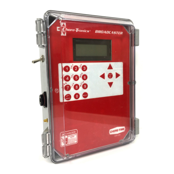
Broadcaster Introduction Getting Familiar with the Control Backup Battery Switch Ethernet Port (A) (used for troubleshooting) Ethernet Port (B) (used to connect to LAN network) Display Cellular Antenna Navigation Connection and Edit Buttons RJ-11 Alphanumeric Telephone Jack Key Pad Power Supply Connection Figure 1. -
Page 8: Alphanumeric Keypad
Introduction Broadcaster Alphanumeric Keypad To choose "B" push #2 twice The Alphanumeric Keypad is used to enter a number directly into a field without having to scroll to the number. The Alphanumeric Keypad can also be used to change the name of some text fields. The first letter above each Key is chosen by pushing that Key once. -
Page 9: Installation
Broadcaster Installation Installation Mounting the Control 18" [45.7cm] Ethernet Port (A) Ethernet Port (B) Telephone Jack Line In Cellular Power Supply Antenna 2461-006 11/2016 Telephone Jack (B) Figure 5. Mounting the Control Broadcaster Setup Disarming the Broadcaster Before Setting up the Broadcaster, it will have to be disarmed. There are two methods to Disarm/Arm the Broadcaster. -
Page 10: Saving The Current Installed Modems
Broadcaster Setup Broadcaster Saving the Current Installed Modems Cellular Modem Setup From the Current Conditions screen, press the Back Button. 1. From the Main Menu, select Setup. 2. Select General. 3. From the General Setup menu screen, scroll down and select Cell Modem Config. 4. -
Page 11: Land Line Modem Setup
Broadcaster Broadcaster Setup Land Line Modem Setup From the Current Conditions screen, press the Back Button. 1. From the Main Menu, select Setup. 2. Select General. 3. From the General Setup menu screen, scroll down and select Land Modem Config. 4. -
Page 12: Main Box Setup
Broadcaster Setup Broadcaster Main Box Setup Base Box Type 1. From the Setup Menu screen, select General. 2. Select Box Type. 3. Select Base. ™ 4. Press Enter to save. The Broadcaster restarts after the BOX TYPE is saved. 5. After the restart, return to General Setup screen to continue with the setup. Box Name 1. -
Page 13: Alert Suspend Time
Broadcaster Broadcaster Setup Alert Suspend Time The time after an alert has been Acknowledged to go back to inactive or call/text if still active. The maximum suspend time is 29:50 (min:seconds). 1. From the Setup Menu screen, select General. 2. Select Alert Suspend Time. 3. -
Page 14: Dialing
Broadcaster Setup Broadcaster Dialing Enter the phone numbers you want to call or text in each of the modems and Server calls. Notes: • Depending on your local system some Landlines will need a 1 added to the front of the phone number. •... -
Page 15: Sms Text Messaging
Broadcaster Broadcaster Setup Adding/Changing Cell Numbers Perform a test cell call in the Dial Test Menu before changing the default. 1. Go to Dialing Setup Screen and select Cellular Calling. 2. Select Dialing Numbers 3. Select the line you want to change and select Enter. 4. -
Page 16: Server Voice And Texting Dialing
Broadcaster Setup Broadcaster Server Voice and Texting Dialing Note: All Server numbers Voice and Text need a "1" added in front of the phone number. 1. From the Setup Menu, select Dialing. 2. Select Server Calling. 3. Select Dialing Numbers. 4. -
Page 17: Acknowledgment Code
Broadcaster Broadcaster Setup (T4) SMS list, fourth number in the list. (P1) Landline list, first number in the list. (SV3) Server Voice list, the third number in the list.. Acknowledgment Code This code is used to Acknowledge all types of Alert calls. Note: The default Acknowledgment code is 123456. -
Page 18: Network Setup
Broadcaster Setup Broadcaster Network Setup Connect all devices to the local Ethernet network (CT3, Broadcaster, and or Broadcaster Aux Box). The Base Box communicates via Ethernet IP addresses. In most of the installs, a Dynamic IP is used in the Broadcaster. The IP is determined by the connected Router. - Page 19 Broadcaster Broadcaster Setup Default Gateway The Gateway is assigned by the Router. Approved AUX List ® Approved AUX List is a list of all devices (Chore-Tronics 3 and Auxiliary boxes) that are to be monitored by the Base Box. ® Adding Chore-Tronics 3 Controls and Auxiliary Boxes 1.
- Page 20 Broadcaster Setup Broadcaster Sleep Mode The Sleep Mode feature allows the user to disable alerts from a specific house, houses, and/or Aux box. The Base Broadcaster box will not send any Alerts from the selected units that are in the Sleep Mode. The time can be set from 1 hour to a maximum of 30 days.
- Page 21 Broadcaster Broadcaster Setup Placing the Base Box in Sleep Mode Note: No Alerts will be sent from any connected device (CT3, Aux Box, or Input) when the Base Box is in Sleep Mode. 1. From the Network Setup menu (Main Menu–>Setup–>Network), select House Sleep Mode. 2.
-
Page 22: History
Broadcaster Setup Broadcaster History View History 1. Select History from the Main Menu. 2. Select View History. 3. The latest Alerts will be displayed. 4. Arrow down to see more past alerts. Copy History A USB drive is needed to download history. DANGER: Electrical Hazard ™... -
Page 23: Auxiliary Box Setup
Broadcaster Auxiliary Box Setup Auxiliary Box Setup Box Type (Auxiliary) 1. From the Main Menu, select Setup. 2. Select General. 3. Select Box Type. 4. Select AUX and press Enter. The Broadcaster will restart. ™ Time and Date (Auxiliary) 1. From the Main Menu, select Setup. 2. -
Page 24: Auxiliary Box Names
Auxiliary Box Setup Broadcaster Auxiliary Box Names 1. Go to the Main Menu and select Setup. 2. Select General. 3. Select Box Name and press Enter. 4. Select Yes and press Enter. 5. Select a Name from the Aux Box Name list and press Enter. Alert Names (Aux.) Refer to the Base Box Alert Digital Inputs Naming procedure. -
Page 25: Broadcaster™ Testing
Broadcaster Broadcaster™ Testing Broadcaster™ Testing Warning: This Device must be tested at least once a week. Failure to do so can result in no alert notification and a loss of production. Call/Text Testing SMS Text Message—A Weekly text message will be sent every Wednesday at noon (the date and time must be set up correctly). -
Page 26: Testing Modems
Testing Modems Broadcaster Testing Modems Landline Modem Testing Note: Modems should be tested at least once per week. 1. Select Dial Test from the Main Menu. 2. Select TEST LANDLINE. 3. Enter the Phone number you want to call. 4. As soon as the last number is entered the Broadcaster ™... -
Page 27: Updating Broadcaster™ Software
Broadcaster Updating Broadcaster™ Software Updating Broadcaster™ Software DANGER: Electrical Hazard 1. Remove all power sources from the Broadcaster ™ 2. Insert the USB drive in the USB hub. Power the Broadcaster ™ back up. USB Drive USB Hub 2461-075 11/2016 3. -
Page 28: Cell Modem Sim Card Installation (Gsm/Att)
Cell Modem Sim Card Installation (GSM/ATT) Broadcaster Cell Modem Sim Card Installation (GSM/ATT) Sim Card Sim Card Mounting Bracket Step 1) Slide to Unlock Step 2) Open Door Step 3) Insert Sim Card Notched Corner Step 4) Close the Door Step 5) Slide to Lock Push down slightly on Sim Card while sliding. -
Page 29: Wiring
Wiring Fiber Ethernet (Wiring CT3 Main Box 6 Port Fiber Switch Tx Rx Tx Rx Ethernet Cable Ethernet Cable Ethernet Cable Broadcaster Ethernet Cable Main Box 8 dry Contact Inputs CT3 Main Box 6 Port Fiber Switch Tx Rx Tx Rx CT3 Controls send specific Alarms directly Ethernet Cable to the Broadcaster Main Box... -
Page 30: Wireless Radios (Ct3 And Other Chore-Tronics Controls) Wiring
Wireless Radios (CT3 and other Chore-Tronics Controls) Wiring Alarm Internet Router CT3 Main Box Ethernet Cable Ethernet Cable Broadcaster Ethernet Cable Main Box Alarm Ethernet Switch 8 dry Contact Inputs CT3 Main Box CT3 Controls send specific Alarms directly to the Broadcaster Main Box Ethernet Cable Broadcaster Aux Box... -
Page 31: Ethernet Cat 5E-6 (Ct3 And Other Chore-Tronics Controls) Wiring
Ethernet Cat 5e-6 (CT3 and other Chore-Tronics Controls) Wiring Internet Router CT3 Main Box Ethernet Cable Ethernet Cable Broadcaster Ethernet Cable Main Box Ethernet Switch 8 dry Contact Inputs CT3 Main Box CT3 Controls send specific Alarms directly to the Broadcaster Main Box Ethernet Cable Broadcaster Aux Box... -
Page 32: Ct2 Alarm Relay Kit (50246) Wiring
CT2 Alarm Relay Kit (50246) Wiring 1.Connect the Flat Cable as shown. 2.Remove the Common Jumper Wired if not needed. 3.All outputs are SPDT dry contack (Com./NC./NC.) 4.Broadcaster connects to the Com and NO. 5.Outputs: 1. High or Low Temperature on any mode temp sensor. 2. -
Page 33: External Alert (Alarm) Wiring
External Alert (Alarm) Wiring Broadcaster I/O Board Max Load 3A @ 30VDC 24 VDC or VAC 24 VDC or VAC Coil External Alert Device Power Supply... -
Page 34: Generator Transfer Alert
Wiring Broadcaster Generator Transfer Alert Power Transfer Box Auxiliary Relay Connection Wiring The Relay in the Transfer box that monitors the current mode of the Power Source must be connected to one of the eight inputs on the IO board. A closed circuit is needed to get an alert. -
Page 35: Broadcaster Io Board's Eight Digital Inputs
Broadcaster Wiring Broadcaster IO Board’s Eight Digital Inputs The eight inputs can be used to monitor any device that is connected to a relay that Closes for an alert. See the examples depicted below. MT2461B... -
Page 36: Parts Listing
Parts Listing 10 11 2434-020b 03/2014... - Page 37 Item Description Part No. 4 x 8 x 11 Control Box 30860-3 Plain Control Box Lid 30859-1 Ethernet alert Base Plate 54018 #8 x .375 HXWH Screw 13019 3.15 Grounding Rail 43384-2 Ground Symbol Decal 2527-63 Ethernet alert Top Plate 54017 Nylon Spacer 43383...
- Page 38 Revisions to this Manual Page No. Description of Change Various Numerous Updates 36032 Contact your nearby Chore-Time distributor or representative for additional parts and information. CTB, Inc. PO Box 2000 Milford, Indiana 46542-2000 USA Phone (574) 658-4101 Email: choretime@choretime.com Internet: www.choretime.com...
Need help?
Do you have a question about the Chore-Tronics Broadcaster and is the answer not in the manual?
Questions and answers