
Related Manuals for Radar Electronics Preco Electronics PVM500

Summary of Contents for Radar Electronics Preco Electronics PVM500
- Page 1 www.radar-electronics.com e-mail.:info@radar-electronics.com TFT LCD Color Monitor PVM500 Operating Manual / Installation Guide...
-
Page 2: Table Of Contents
CONTENTS Product Description ................... 1 Features..................... 2 Contents ....................2 Functions ....................2 Bracket Installation ..................5 Cable Connection ..................6 Specifications .................... 7 Warranty Information ................8... -
Page 3: Product Description
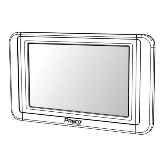
Product Description The Preco Electronics PVM500 is a light-duty, single camera monitor ® design for closed cab use. The PVM500 contains one triggered input, allowing the monitor to be switched on when it is required, i.e., while in reverse. Safeguard Instructions Please read the following cautions carefully before using this product. -
Page 4: Features
Features High resolution 5” LCD panel • All functions are displayed on screen (OSD function) • (ENG-DEU-ITA-FRA-ESP-JPN) Menu system displays 6 languages • Contents PVM500 Bracket Trigger Wire Manual Functions 1. TFT LCD 2. Menu Button 3. Volume Buttons 4. Power Button – On/Off 5. - Page 5 FUNCTIONS, Continued Power ON/OFF POWER ON: push to POWER ON (STAND BY state is OFF) POWER OFF: push again to POWER OFF Menu The Menu changes [BRIGHTNESS] - [CONTRAST] - [COLOR] - [TINT] - [DIMMER] - [LANGUAGE] - [CAM] - [RESET] [VOLUME]: Volume control Push △▽...
- Page 6 [COLOR]: Density adjusting on screen color On Color setting mode, △▽ buttons control density of the screen color. (0~100) [0: Low density / 100: High density] CO LO R [TINT]: Screen color adjusting On Tint setting mode △▽ buttons control the screen color. (0~100) TINT [DIMMER]: Automatic brightness adjusting...
-
Page 7: Bracket Installation
Bracket Installation Remove protective tape covering from bottom of stand and attach the stand with double stick tape. Secure to stand using the 3 enclosed screws. Connect monitorandstand. Tel: +386 3 4900 800 http://radar-electronics.com/ 3700243A Copyright 2017 Page 5... -
Page 8: Cable Connection
Cable Connection To avoid a short circuit, disconnect the ground terminal of the vehicle battery prior to installation. The arrows on the camera connection must align before fully inserting connectors together. Test after installation to insure proper function of both the monitor and camera. -
Page 9: Specifications
Specifications <LCD Panel> 5” (127 mm) LCD size Image ratio 16 : 9 Resolution 800 x3(RGB) x 480 Brightness 500cd 700 : 1 Contrast range Active area 4.5” (108.0 mm)(W) x 2.55” (64.8 mm)(H) 70(L) / 70(R) / 50(T) / 70(B) Viewing angle <Monitor>... -
Page 10: Warranty Information
Warranty Information MANUFACTURER LIMITED WARRANTY AND LIMITATION OF LIABILITY Manufacturer warrants that on the Date of Purchase this Product will conform to Manufacturer's published specifications for the product, which are available from Manufacturer on request, and Manufacturer warrants that the product is free from defects in materials and workmanship. - Page 11 www.radar-electronics.com e-mail.:info@radar-electronics.com tel.. 00386 3 4900 800 Tel: +386 3 4900 800 http://radar-electronics.com/ 3700243A Copyright 2017 Page 9...
Need help?
Do you have a question about the Preco Electronics PVM500 and is the answer not in the manual?
Questions and answers