
Related Manuals for Jungheinrich ERE Series

Summary of Contents for Jungheinrich ERE Series
- Page 1 07.09 - Operating instructions Operating instructions 51159400 ERE 120n 11.13...
- Page 2 Used to indicate standard equipment. Used to indicate optional equipment. Our trucks are subject to ongoing development. Jungheinrich reserves the right to alter the design, equipment and technical features of the truck. No guarantee of particular features of the truck should therefore be inferred from the present operating instructions.
-
Page 4: Table Of Contents
Index Correct use and application Truck Description Application ................... B 1 Assemblies ..................B 2 Specifications ..................B 3 Performance data ................B 3 Dimensions ..................B 3 EN norms .................... B 7 Conditions of use ................B 7 Identification points and data plates ............ B 8 Truck data plate .................. - Page 5 Operation Safety Regulations for the Operation of Forklift Trucks ...... E 1 Controls and Displays ................. E 2 Starting up the truck ................E 6 Industrial truck operation ..............E 7 Safety regulations for truck operation ..........E 7 Travel, Steering, Braking ..............E 8 Collecting and depositing loads ............
- Page 6 Appendix JH Traction Battery Operating Instructions These operating instructions apply only to Jungheinrich battery models. If using another brand, refer to the manufacturer's operating instructions.
-
Page 8: A Correct Use And Application
A Correct use and application The “Guidelines for the Correct Use and Application of Industrial Trucks” (VDMA) are supplied with the truck. The guidelines form part of these operating instructions and must be observed. National regulations apply in full. The truck described in the present operator manual is an industrial truck designed for lifting and transporting load units. -
Page 10: B Truck Description
B Truck Description Application The truck is a tiller operated electric pallet truck with a folding operator platform and side arms. A fixed operator platform is optionally available. The truck is designed for lifting and transporting goods on a level surface. The truck can pick up, outside the load wheel area, open bottom or diagonal board pallets as well as roll cages. -
Page 11: Assemblies
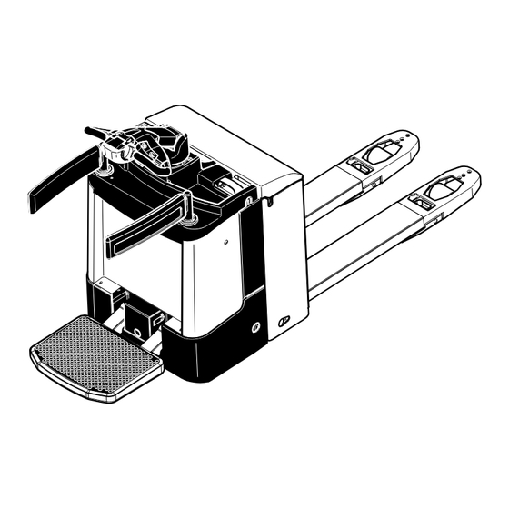
Assemblies 3, 6 4, 5 Item Description Item Description t Travel switch t Castor wheel t Tiller t Drive wheel o Display instrument t Folding operator platform (CanDis) t Key switch t Ram protection o Keypad t Side arm (CanCode) t Battery discharge o Fixed operator platform indicator... -
Page 12: Specifications
Specifications Technical data specified in accordance with VDI 2198. Technical modifications and additions reserved. Performance data Description Capacity 2.000 Load centre of gravity Travel speed, km/h pedestrian (walk-along) mode w / w.o. load Travel speed, 7,5 / 8,5 km/h operator position mode w / w.o. load Lift time w / w.o. - Page 13 Dimensions sheet with folding platform 1006...
- Page 14 Dimensions sheet with fixed platform...
- Page 15 Length including fork shank I = 754 mm (walk-along mode) Details in mm 1000 1754 1326 * 1000 1537 1978 1150 1904 1476 * 1200 1687 2178 1200 1954 1526 * 1200 1737 2178 1400 2154 1726 * 1159 1400 1937 2378 1600...
-
Page 16: En Norms
EN norms Noise emission: 66 dB(A) in accordance with EN 12053 as harmonised with ISO 4871. The noise emission level is calculated in accordance with standard procedures and takes into account the noise level when travelling, lifting and when idle. The noise level is measured at the driver’s ear. -
Page 17: Identification Points And Data Plates
Identification points and data plates Item Description Truck data plate Rated capacity Strap point for crane lifting Battery data plate The truck data plate (15) is visible when the load section is raised. The battery data plate (18) can be seen on the battery (see Chapter D). -
Page 18: Truck Data Plate
Truck data plate Item Description Item Description Type Manufacturer’s logo Name Max. battery weight in kg Battery: Voltage (V) Min. battery weight in kg Rated capacity (kg) Output (kW) Net weight w.o. battery (kg) Load centre (mm) Net weight with battery (kg) Year of manufacture Manufacturer Serial No. - Page 19 B 10...
-
Page 20: C Transport And Commissioning
C Transport and Commissioning Lifting by crane Only use lifting gear with sufficient capacity (for truck weight see truck data plate, chapter B). Lifting gear attachment points (1) are provided on the chassis and the fork in case the truck is to be lifted or trans- ported by crane. -
Page 21: Removing The Transport Lock
Removing the Transport Lock There is an instruction decal by the front panel for the transport retainer (2), this must be removed once the battery has been installed. – Fold down the driver’s platform. – Open the front panel (see Chapter F). –... -
Page 22: Operating The Truck Without Its Own Drive System
Operating the truck without its own drive system This operating mode is not permitted when negotiating inclines and gradients. If the truck has to be moved after a failure has rendered it immobile, proceed as follows: – Set the key switch OFF and remove the key. –... -
Page 23: Securing The Truck During Transport
Securing the truck during transport The truck must be securely fastened when being transported on a lorry or a trailer. The lorry / trailer must have fastening rings. Fold the side protection and the folding platform in or up so that they do not protrude beyond the geometry of the truck. –... -
Page 24: D Battery Maintenance, Charging & Replacement
D Battery Maintenance, Charging & Replacement Safety regulations for handling acid batteries Park the truck securely before carrying out any work on the batteries (see Chapter E). Maintenance personnel: Batteries may only be charged, serviced or replaced by trained personnel. The present operator manual and the manufacturer’s instructions concerning batteries and charging stations must be observed when carrying out the work. -
Page 25: Battery Types
Battery types The battery types correspond to EN 60254-2. The following table shows the combinations to be used, with reference to their capacity: Battery type Battery Weight Battery Weight compartment compartment approx. 227 mm approx. 299 mm 24 volt battery 2 EPzS 240 Ah 231 kg 3 EPzS 360 Ah... -
Page 26: Charging The Battery
Charging the battery To charge the battery, the truck must be parked in a closed and properly ventilated room. When charging, the tops of the battery cells must be exposed to provide sufficient ventilation. Do not place any metal objects on the battery. Before charging, check all cables and plug connections for visible signs of damage. -
Page 27: Battery Removal And Installation
Battery removal and installation Changing the battery from the top (t) The truck must be level. To prevent short circuits, batteries with exposed terminals or connectors must be covered with a rubber mat. Place the battery connector or the battery cable in such a way that they will not get caught on the truck when the battery is removed. -
Page 28: Lateral Battery Removal (O)
Lateral Battery Removal (o) The truck must be level. To prevent short circuits, batteries with exposed terminals or connectors must be covered with a rubber mat. Place the battery connector or the battery cable in such a way that they will not get caught on the truck when the battery is removed. -
Page 30: Safety Regulations For The Operation Of Forklift Trucks
E Operation Safety Regulations for the Operation of Forklift Trucks Driver authorisation: The forklift truck may only be used by suitably trained personnel, who have demonstrated to the proprietor or his representative that they can drive and handle loads and have been authorised to operate the truck by the proprietor or his representative. -
Page 31: Controls And Displays
Controls and Displays Item Control / Display Function t Pedestrian mode: Folding operator platform – Operator platform in upper position: Pedestrian travel speed restricted to max. 4.5 km/h. Rider mode, operator platform acts as deadman switch: – Operator platform in lower position and unladen: travelling inhibited. - Page 32 9, 10 11, 12...
- Page 33 Item Control / Display Function t Switches control current on and off. Removing Key switch the key prevents the truck from being switched on by unauthorised personnel. o Replaces the key switch. Code lock Switches control current on and off. Releases the truck functions.
- Page 34 9, 10 11, 12...
-
Page 35: Starting Up The Truck
Starting up the truck Before the truck can be commissioned, operated or a load unit lifted, the driver must ensure that there is nobody within the hazardous area. Checks and operations to be performed before starting daily work – Visually inspect the entire truck (in particular wheels and load handler) for obvious damage. -
Page 36: Industrial Truck Operation
Industrial truck operation Safety regulations for truck operation Travel routes and work areas: Only use lanes and routes specifically designated for truck traffic. Unauthorised persons must stay away from work areas. Loads must only be stored in places specially designated for this purpose. Driving conduct: The driver must adapt the travel speed to local conditions. -
Page 37: Travel, Steering, Braking
Travel, Steering, Braking Be extremely careful when driving and steering, especially when operating outside the geometry of the truck. In walk-along mode make sure you have sufficient distance from the truck. Emergency Disconnect – Remove the battery connector (13). All electrical functions are deactivated. Emergency Stop Automatic braking (emergency stop) occurs when the tiller (5) is released –... - Page 39 Travelling on inclines Loads must always be carried at that end of the truck facing uphill. Steering In narrow bends the driver extends beyond the geometry of the truck. – Move the tiller (5) to the left or right. Braking The brake pattern of the truck depends largely on the ground conditions.
-
Page 40: Collecting And Depositing Loads
Collecting and depositing loads Before picking up a load, the driver must ensure that it is correctly palletised and that the capacity of the truck is not exceeded. It is forbidden to collect long loads at an angle. – Fully insert the truck and the load handler underneath the load unit. -
Page 41: Parking The Truck Securely
Parking the truck securely When you leave the truck it must be securely parked even if you only intend to leave it for a short time. – Do not park the truck on an incline. – Fully lower the load forks. –... -
Page 42: Keypad (Cancode) (O)
Keypad (CanCode) (o) The keypad consists of 10 digit keys, a Set key and a o key. Activation of the travel programs via switches 1,2,3 is indicated by green LEDs. The o key indicates operating statuses via a red/ green LED. It contains the following functions: –... - Page 43 Starting the truck for the first time When the main switch is turned on the LED (16) goes red. When you enter the correct operator code (factory setting 2-5-8-0) the LED (16) turns green. If the wrong code is entered LED (16) flashes red for two seconds. The correct code can then be entered.
-
Page 44: Travel Programs
Travel programs Press the digit keys 1, 2, and 3 to select any of three travel programs. The activated programme is indicated by the green LEDs (18), (19), (20) in the corresponding key. The travel programs differ with respect to travel speed, acceleration and deceleration force. -
Page 45: Parameter Settings
Parameter Settings To change the truck setting you must enter the master code. The factory setting for the master code is 7-2-9-5. When starting the truck for the first time, change the master code (see Section 5.1). Safety instructions for trucks with a display instrument (CanDis (o)) –... - Page 46 Setting procedure for trucks with and without display instrument (CanDis (o)): – Enter the three digit parameter number, confirm with the Set key (17). – The display instrument (CanDis (o)) continues to display the operating hours. If the display changes, cancel the setting with the o key (21) and restart from the beginning.
- Page 47 Function Range of Standard Comments Setting Setting Procedure Code Lock 002 Change Operator Code 0000 - 9999 (LED 18 flashes) Enter current code 00000 - 99999 Confirm (Set) 000000 - 999999 (LED 19 flashes) Enter new code Confirm (Set) (LED 20 flashes) Repeat code entry confirm 003 Delete Operator Code...
- Page 48 Function Range of Standard Comments Setting Setting Procedure Code Lock 024 User code configuration 1112 The travel programs are connected to the user code.The travel programs can be individually released or blocked for each user code. A start travel program can be assigned to each user code.
-
Page 49: Travel Parameters
Travel parameters For trucks without a display instrument (CanDis (o)) the parameters must be adjusted with particular care to avoid incorrect entries. The following example shows the parameter setting for the acceleration of travel program 1 (parameter 0256). Acceleration example –... - Page 50 The following parameters may be entered. Travel programs (speeds and acceleration w.o. load) Function Range of Standard Comments Setting Setting Travel program 1 0256 Acceleration 0 - 9 Platform folded (0,13 - 1,88 m/s²) 0,67 m/s² out, safety gate folded out 0264 Max.
- Page 51 Function Range of Standard Comments Setting Setting Travel program 2 0272 Acceleration 0 - 9 Platform folded (0,13 - 1,88 m/s²) 1,08 m/s² out, safety gate folded out 0280 Max. speed in drive 0 - 9 direction (4,5 - 9,0 km/h) 8,5 km/h 0284 Max.
- Page 52 Function Range of Standard Comments Setting Setting Travel program 3 0288 Acceleration 0 - 9 Platform folded (0,13 - 1,88 m/s²) 1,62 m/s² out, safety gate folded out 0296 Max. speed in drive 0 - 9 direction (4,5 - 9,0 km/h) 8,5 km/h 0300 Max.
-
Page 53: Battery Parameters
Battery parameters For trucks without a display instrument (CanDis (o)) the parameters must be adjusted with particular care to avoid incorrect entries. The parameters are set in the same way as for the travel parameters. The following parameters may be entered. Function Range of Standard... -
Page 54: Battery Discharge Indicator (T)
Battery Discharge Indicator (t) When the truck has been released via the key switch or CanCode, the battery charge status is displayed. The colours of the LEDs (9) represent the following conditions: LED colour Rating Green Standard battery residual capacity 40 - 100 % Maintenance free battery residual capacity 60 - 100 %... -
Page 55: Display Instrument (Candis) (O)
Display instrument (CanDis) (o) The instrument indicates: 22 Capacity display bars Battery residual charge 23 Stop symbol; lift cutout, battery charge required 24 6 digit LCD display; hourmeter; entry display; error display 25 T symbol appears during operation when the discharge indicator is set to maintenance-free battery 26 Attention pre-warning symbol, battery charge required... -
Page 56: Discharge Monitor Function
Discharge monitor function When the discharge monitor function is enabled, lifting is cut out when the discharge limit is reached (the Stop LED is lit). Travel and lowering are still possible. For wet batteries the residual capacity is 20%, for maintenance-free batteries it is 40%. The batteries should be recharged when they reach 30% (for wet batteries) or 50% (for maintenance-free batteries). - Page 57 E 28...
-
Page 58: Troubleshooting
Troubleshooting This chapter is designed to help the user identify and rectify basic faults or the results of incorrect operation. When locating a fault, proceed in the order shown in the table. Fault Possible cause Action Truck does – Battery connector –... - Page 59 E 30...
-
Page 60: F Truck Maintenance
F Truck Maintenance Operational safety and environmental protection The servicing and inspection operations contained in this chapter must be performed in accordance with the intervals indicated in the servicing checklists. Any modification to the forklift truck assemblies, in particular the safety mechanisms, is prohibited. - Page 61 Electrical System: Only suitably trained personnel may operate on the truck’s electrical system. Before working on the electrical system, take all precautionary measures to avoid electric shocks. For battery-operated trucks, also de-energise the truck by removing the battery connector. Welding: To avoid damaging electric or electronic components, remove these from the truck before performing welding operations.
-
Page 62: Servicing And Inspection
The application conditions of an industrial truck have a considerable impact on the wear of the service components. We recommend that a Jungheinrich customer adviser carries out an application analysis on site to work out specific service intervals to prevent damage due to wear. -
Page 63: Maintenance Checklist
Maintenance Checklist Maintenance intervals = t W A B C Standard Cold Store Brake 1.1 Check magnetic brake air gap. Electrics 2.1 Test instruments, displays and control switches. 2.2 Test warning and safety device. 2.3 Check fuse ratings. 2.4 Make sure wire connections are secure and check for damage. - Page 64 Maintenance intervals = t W A B C Standard Cold Store Hydraulic 6.1 Check operation, wear and setting. operation 6.2 Check forks for wear and damage. 6.3 Test hydraulic system. 6.4 Check that hose and pipe lines and their connections are secure, check for leaks and damage.
-
Page 65: Maintenance Schedule
Maintenance Schedule 0,7l 0,55 l g Contact surfaces 1) Compound ratio for cold store usage 1 : 1 Grease nipples Hydraulic oil filler neck 2) 1.25 – 1.3 litres depending on the type of transmission (always up to the lower mark of the Transmission oil filler neck filler neck) Transmission oil drain plug... -
Page 66: Fuels, Coolants And Lubricants
Fuels, coolants and lubricants Handling consumables: Consumables must always be handled correctly. Follow the manufacturer’s instructions. Improper handling is hazardous to health, life and the environment. Consumables must only be stored in appropriate containers. They may be flammable and must therefore not come into contact with hot components or naked flames. -
Page 67: Maintenance And Repairs
Maintenance and Repairs Preparing the truck for maintenance and repairs All necessary safety measures must be taken to avoid accidents when carrying out maintenance and repairs. The following preparations must be made: – Parking the truck securely (see Chapter E). Opening the battery panel (see chapter D). -
Page 68: Replacing The Drive Wheel
Replacing the drive wheel The drive wheel must only be replaced by authorised service personnel. Checking the hydraulic oil level – Prepare the truck for maintenance and repairs (see section 6.1). – Opening the front panel (see Section 6.3). – Check hydraulic oil level in hydraulic reservoir (7). -
Page 69: Checking Electrical Fuses
Checking electrical fuses – Prepare the truck for maintenance and repairs (see Section 6.1). – Dismantle the front panel (see Section 6.3). – Check rating of all fuses in accordance with table, replace if necessary. Item Description To protect: Rating Traction / Lift motor 200 A Solenoid / magnetic brake... -
Page 70: Recommissioning
Recommissioning The truck may only be recommissioned after cleaning or repair work, once the following operations have been performed. – Test horn. – Test main switch operation. – Test brake. – Lubricate the truck in accordance with the maintenance schedule. Decommissioning the industrial truck If the industrial truck is to be decommissioned for more than two months, e.g. -
Page 71: Restoring The Truck To Operation After Decommissioning
Carry out a safety check in accordance with national regulations. Junheinrich recommends checks in accordance with FEM Guideline 4.004. Jungheinrich has a special safety department with trained personnel to carry out such checks. The truck must be inspected at least annually (refer to national regulations) or after any unusual event by a qualified inspector. -
Page 72: Traction Battery Appendix
A Traction Battery Appendix Contents Traction Battery Appendix............Correct Use and Application..............Data plate ....................Safety Instructions, Warning Indications and other Notes ....... Lead acid batteries with armour plated cells and liquid electrolyte..Description....................Operation....................Servicing lead-acid batteries with armour plated cells......PzV and PzV-BS lead-acid batteries with sealed armour plated cells.. -
Page 73: Correct Use And Application
Correct Use and Application Failure to observe the operating instructions, carrying out repairs with non-original spare parts, tampering with the battery or using electrolyte additives will invalidate the warranty. Observe the instructions for maintaining the safety rating during operation for batteries in accordance with Ex I and Ex II (see relevant certification). -
Page 74: Safety Instructions, Warning Indications And Other Notes
Safety Instructions, Warning Indications and other Notes Used batteries must be treated as hazardous waste. These batteries are marked with the recycling symbol and the sign showing a crossed-out rubbish bin, and should not be disposed of with ordinary household waste. waste. -
Page 75: Lead Acid Batteries With Armour Plated Cells And Liquid Electrolyte
Lead acid batteries with armour plated cells and liquid electrolyte Description Jungheinrich traction batteries are lead acid batteries with armour plated cells and liquid electrolyte. The names of the traction batteries are PzS, PzB, PzS Lib and PzM. Electrolyte The rated density of the electrolyte assumes a temperature of 30°C and the rated electrolyte level is fully charged. -
Page 76: Operation
Operation 4.2.1 Commissioning unfilled batteries The operations required must be carried out by the manufacturer's customer service department or a customer service organisation authorised by the manufacturer. 4.2.2 Commissioning filled and charged batteries Checks and operations to be performed before starting daily work Procedure •... - Page 77 4.2.4 Charging the battery WARNING! The gases produced during charging can cause explosions The battery gives off a mixture of oxygen and hydrogen (electrolytic gas) during charging. Gassing is a chemical process. This gas mixture is highly explosive and must not be ignited. Always disconnect the charger and truck before connecting or disconnecting the charger and battery.
- Page 78 The electrolyte temperature rises by approx. 10 K during charging. Charging should therefore only begin when the electrolyte temperature is below 45°C. The electrolyte temperature of batteries must be at least +10°C before charging. Otherwise the battery will not charge correctly. Below 10°C the battery is insufficiently charged with standard charging systems.
-
Page 79: Servicing Lead-Acid Batteries With Armour Plated Cells
Servicing lead-acid batteries with armour plated cells Water quality The quality of the water used to fill up electrolyte must correspond to purified or distilled water. Purified water can be produced through distillation or ion exchangers and is then suitable for the production of electrolyte. 4.3.1 Daily –... -
Page 80: Pzv And Pzv-Bs Lead-Acid Batteries With Sealed Armour Plated Cells
PzV and PzV-BS lead-acid batteries with sealed armour plated cells Description PzV batteries are sealed batteries with fixed electrolytes, to which no water can be added over the entire lifespan of the battery. Relief valves are used as plugs which are destroyed when opened. -
Page 81: Operation
Operation 5.2.1 Commissioning Checks and operations to be performed before starting daily work Procedure • Make sure the battery is in physically good condition. • Make sure the terminals are correct (positive to positive and negative to negative) and check that contacts on the battery terminal conducting system are secure. •... - Page 82 NOTE Charging the battery incorrectly can result in material damage. Incorrect battery charging can result in overloading of the electric wires and contacts, hazardous gas formation and electrolyte leakage from the cells. Always charge the battery with DC current. All DIN 41773 charging procedures are permitted in the format approved by the manufacturer.
- Page 83 Charging the battery Requirements – Electrolyte temperature between +15°C and 35°C Procedure • Open or take off the tray lid or covers from the battery compartment. • Connect the battery to the switched off charger, ensuring the terminals are connect (positive to positive and negative to negative).
-
Page 84: Servicing Pzv And Pzv-Bs Lead-Acid Batteries With Sealed Armour Plated Cells
Servicing PzV and PzV-BS lead-acid batteries with sealed armour plated cells Do not add water! 5.3.1 Daily – Charge the battery after each discharge. 5.3.2 Weekly – Visually inspect for dirt and physical damage. 5.3.3 Every three months – Measure and record the overall voltage. –... -
Page 85: Aquamatik Water Replenishment System
Aquamatik water replenishment system Water replenishment system design > 3 m Water container Tap connection with ball cock Flow indicator Shut-off cock Locking coupling Battery lock connector... -
Page 86: Functional Description
Functional Description The Aquamatik water replenishment system is used to adjust the rated electrolyte level automatically on traction batteries for industrial trucks. The battery cells are interconnected through hoses and are attached to the water supply (e.g. water container) through a plug connection. When the shut-off cock is opened all the cells are filled with water. -
Page 87: Filling Time
Filling time The filling time for a battery depends on the electrolyte level, the ambient temperature and the filling pressure. Filling ends automatically. The water supply line must be disconnected from the battery when the water has been filled. Water quality The quality of the water used to fill up electrolyte must correspond to purified or distilled water. -
Page 88: Cleaning Measures
Cleaning measures The plug systems must only be cleaned with purified water in accordance with DIN 43530-4. No parts of the plugs must come into contact with solvent-based materials or soap. 6.10 Service mobile vehicle Mobile water filling vehicle with pump and filling gun to fill individual cells. The immersion pump in the container generates the necessary filling pressure. -
Page 89: Electrolyte Circulation
Electrolyte circulation Functional Description Electrolyte circulation ensures the supply of air during charging to mix the electrolyte, thereby preventing any acid layer, shortening the charge time (charge factor approx. 1.07) and reducing the formation of gas during charging. The charger must be suitable for the battery and electrolyte circulation. - Page 90 NOTE If an installed electrolyte circulation system is seldom used or not used at all, or if the battery is subjected to severe temperature fluctuations, the electrolyte may flow back into the hose system. Attach a separate coupling system to the air inlet line, such as: locking coupling on the battery side and through-coupling on the air supply side.
-
Page 91: Cleaning Batteries
Cleaning batteries Batteries and trays must be cleaned in order to – maintain cell insulation and protect cells from ground or external conductive parts. – Avoid damage from corrosion and stray currents. – Avoid excessive and varying automatic discharge of the individual cells or block batteries due to stray currents. - Page 92 Cleaning the battery with a high pressure cleaner Requirements – Cell connectors tight, plugged in securely – Cell plugs closed Procedure • Follow the high pressure cleaner's user instructions. • Do not use any cleaning additives. • Observe the permissible cleaning device temperature setting of 140°C. This generally ensures that the temperature does not exceed 60°C at a distance of 30cm behind the outlet nozzle.
-
Page 93: Storing The Battery
Storing the battery NOTE The battery should not be stored for longer than 3 months without charging as otherwise it will no longer be functional. If the battery is to be taken out of service for a long period, it should be stored fully charged in a dry room protected from frost.
Need help?
Do you have a question about the ERE Series and is the answer not in the manual?
Questions and answers