
Related Manuals for JBL TUNE600BTNC


Summary of Contents for JBL TUNE600BTNC
- Page 1 LinX Series Linear Motor - User Guide D-000168 Rev 02 D-000168 Rev 02 ANCA Motion...
- Page 2 Page intentionally left blank...
- Page 3 LinX Series Linear Motor - User Guide LinX Series Linear Motor - User Guide Document Reference: D-000168 Rev 02 Effective: 25-08-2017 © ANCA Motion Pty. Ltd. ANCA Motion D-000168 Rev 02...
- Page 4 LinX Series Linear Motor - User Guide Page intentionally left blank D-000168 Rev 02 ANCA Motion...
- Page 5 LinX Series Linear Motor - User Guide Chapter Summaries Safety General product safety information Introduction About this user guide, terms and abbreviations Product Overview About LinX, features, catalogue number interpretation System Design How to design a LinX system for your application Specifications Electrical, thermal and mechanical Installation...
-
Page 6: Table Of Contents
LinX Series Linear Motor - User Guide Table of Contents Safety ................................. 1 General Safety ............................1 Introduction............................... 3 About this User Guide ..........................3 Terms and Abbreviations ........................3 Trademarks ............................. 3 Product Overview ............................. 4 About LinX ............................... 4 Features .............................. - Page 7 LinX Series Linear Motor - User Guide Electrical ..............................19 5.1.1 Air-Natural Cooling Behaviour ....................20 5.1.2 Fluid Cooling Behaviour ......................20 Force vs. Speed Characteristics ......................20 Mechanical ............................23 5.3.1 Forcer ............................23 5.3.2 Shaft ............................23 5.3.3 Connector ..........................
-
Page 9: Safety
Safety Safety WARNING: Cylindrical motor shafts contain powerful permanent magnets. People with pacemakers, AICD or similar medical devices should maintain a minimum distance of 50cm from the shaft. DANGER HIGH VOLTAGE: Ensure power has been completely disconnected before touching electrical connections. - Page 10 LinX Series Linear Motor - User Guide Clean or inspect the equipment only after isolating all power sources. Only suitably qualified personnel should install, operate, repair and/or replace this equipment. Ensure all external wiring is clearly labelled. This will assist you and your colleagues in identifying possible electrical safety hazards.
-
Page 11: Introduction
Introduction Introduction About this User Guide This user guide provides the required information for planning to install, installation and servicing of the LinX cylindrical linear motor. It has been written specifically to meet the needs of qualified engineers, tradespersons, technicians and operators. Terms and Abbreviations Ground root mean square... -
Page 12: Product Overview
LinX Series Linear Motor - User Guide Product Overview About LinX The ANCA Motion Patent Pending LinX cylindrical linear motor is a 3 phase brushless AC permanent magnet motor which provides improved performance at lower cost when compared to conventional flat linear motors and rotary motors. -
Page 13: The Linx System
Product Overview Low installation and maintenance costs – Simple construction, non-critical air gap and no physical contact between shaft and forcer results in less time spent in machine construction and downtime. Efficient cooling and thermal barrier – Standalone thermal stability (fluid cooling options available for increased performance). -
Page 14: Product Range
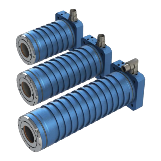
LinX Series Linear Motor - User Guide Product Range TLMS-18P0-SA00 TLMS-27P0-SA00 TLMS-36P0-RA00 Peak Force 2136 N Peak Force 3204 N Peak Force 4272 N Cont. Force Fluid 335 N Cont. Force Fluid 510 N Cont. Force Fluid 630 N Cont. Force Air 207 N Cont. - Page 15 Product Overview TLS50-0840-S Magnet option S: Standard Diameter Length 50: 51mm XXXX mm E.g. 0840: 840mm Figure 3-4 – Shaft Catalogue Number ANCA Motion D-000168 Rev 02...
-
Page 16: System Design
LinX Series Linear Motor - User Guide System Design System Components The design of the LinX cylindrical motor allows for simple replacement of standard ball-screw motors. However, to achieve the best performance with LinX, the system must be optimized. This chapter will describe the main components to consider when designing a system. -
Page 17: Forcer
System Design The LinX shaft produces a strong magnetic field and the effect of this field on surrounding parts and components should be considered during system design. Relevant effects of the strong magnetic field include: Attraction between the shaft and ferrous or magnetic objects. This magnetic force may cause bending in longer shafts. - Page 18 LinX Series Linear Motor - User Guide Peak Force – Identify the peak force required for the application. A forcer will only be able to produce its peak force for a short period of time; the duty cycle also needs to be considered. ...
-
Page 19: Brake
System Design Figure 4-2 - Air cooled forcer mounting example Figure 4-3 - Fluid cooled forcer mounting example DANGER: The forcer must be earthed via the armature connector to prevent the possiblility of electric shock during motor operation. 4.2.4 Brake An external brake should be considered for all applications to prevent damage to systems or users in the event of a failure or fault. -
Page 20: Vertical Applications
LinX Series Linear Motor - User Guide The brake must be chosen so that it provides enough force to resist gravity, inertia and machine operation. The kinetic energy of the moving load will be converted into heat due to friction when the brake is applied. The amount of kinetic energy must be taken into account to prevent damage to the brake due to overheating. -
Page 21: Forcer
System Design SHAFT CENTER HEIGHT UNSUPPORTED SHAFT LENGTH Figure 4-4 - Recommended shaft sag compensation method NOTE: The recommended method for shaft sag only applies to for sag up to 1.6mm. If the sag exceeds this value, additional countermeasures should be taken. Please contact ANCA Motion for more information. 4.3.2 Forcer WARNING: The shaft is not designed to be a load bearing element. -
Page 22: Linear Encoder
LinX Series Linear Motor - User Guide Linear Encoder The linear encoder is used to provide position feedback to the servo drive to allow for accurate control of the LinX motor. The type of encoder used depends greatly on the application; factors such as the required precision, operating environment and servo drive signaling requirements need to be taken into account. -
Page 23: Operating Environment
System Design Conditions Nominal Continuous sensor current 25°C ambient (mA) 300°C ambient Sensed temperature (C) Sensor Resistance (Ω) 25°C 577R 603R 629R Sensor Resistance (Ω) 140°C 1216R 1262R 1309R Isolation between Sensor and Tested at 2400VDC for 1 second UVW phases Table 4-1 - KTY84/130 Temperature Sensor Characteristics Resistance (2mA Continuous Sensor Current) 1400... -
Page 24: Multi-Axis Systems
LinX Series Linear Motor - User Guide Multi-Axis Systems The LinX linear motor system allows for various multi-axis configurations. This can include a single drive and motor for each axis, multiple forcers on a single shaft or two motors moving a gantry. These various configurations can be combined as required for the application. -
Page 25: Multi Forcer
System Design 4.8.2 Multi Forcer Figure 4-7 – Multiple Forcers Unlike ball-screw systems, the multiple LinX forcers can operate on a single shaft to increase the force applied by an axis. These forcers can be synchronized or act completely independently depending on the application. This setup allows for increased flexibility in machine design while providing a compact and cost effective solution. - Page 26 LinX Series Linear Motor - User Guide Figure 4-9 – Parallel Forcers D-000168 Rev 02 ANCA Motion...
-
Page 27: Specifications
Specifications Specifications Electrical TLMS-18P TLMS-27P TLMS-36P TLMS-36H Max Continuous Force (N) Fluid/Air 335 / 207 510 / 290 630 / 360 630 / 360 Max Continuous Current (Arms) Fluid/Air 3.85 / 2.38 5.86 / 3.33 7.24 / 4.14 3.62 / 2.07 Peak Force over 1 second (N) 2136 3204... -
Page 28: Air-Natural Cooling Behaviour
LinX Series Linear Motor - User Guide TLMS-18P TLMS-27P TLMS-36P TLMS-36H Maximum Shaft Temperature (°C) Maximum Winding Temperature (°C) Motor Temperature Class H (180°C) H (180°C) H (180°C) H (180°C) Thermal Time Constant (minutes) 40 / 80 45 / 90 50 / 100 50 / 100 Fluid/Air... - Page 29 Specifications TLMS-18P Force vs. Speed 2500 2000 1500 1000 10000 20000 30000 40000 50000 60000 70000 80000 90000 100000 Speed (mm/min) Peak Force (N) (300V@25˚C) Peak Force (N) (300V@130˚C) Peak Force (N) (600V) Figure 5-1 - TLMS-18P Peak Force vs. Speed TLMS-27P Force vs.
- Page 30 LinX Series Linear Motor - User Guide TLMS-36P Force vs. Speed 4500 4000 3500 3000 2500 2000 1500 1000 10000 20000 30000 40000 50000 60000 70000 80000 90000 100000 Speed (mm/min) Peak Force (N) (300V@25˚C) Peak Force (N) (300V@130˚C) Peak Force (N) (600V) Figure 5-3 - TLMS-36P Peak Force vs.
-
Page 31: Mechanical
Specifications Mechanical NOTE: The motor housing tolerances must be considered when designing a system for fluid cooling. 9.75 9.75 Figure 5-5 - Mechanical Dimensions 5.3.1 Forcer TLMS-18P TLMS-27P TLMS-36P TLMS-36H Length [Lm] (mm) 210.5 300.5 390.5 390.5 Weight (kg) 11.4 11.4 5.3.2 Shaft... - Page 32 LinX Series Linear Motor - User Guide 1020 1050 1080 1110 1140 1170 1200 1230 1260 1290 1320 1350 1020 1380 1050 1410 1080 1440 1110 1020 1470 1140 1050 1500 1170 1080 1530 1200 1110 1020 1560 1230 1140 1050 1590 1260...
-
Page 33: Connector
Specifications NOTE: Longer shafts are available. Please contact ANCA Motion for more information. 5.3.3 Connector Figure 5-6 – Connector Dimensions Pin Number Label U Phase V Phase Temperature + Temperature - W Phase Connector Case Table 5-3 - Motor power pin allocation Recommended Ø... - Page 34 LinX Series Linear Motor - User Guide D-000168 Rev 02 ANCA Motion...
-
Page 35: Installation
Installation Installation Unpacking WARNING: Cylindrical motor shafts contain powerful permanent magnets. People with a pacemaker, AICD or similar medical devices should maintain a minimum distance of 30cm from the shaft. WARNING: The shaft emits a very strong magnetic field, always use caution when handling. To avoid injury, keep fingers and other body parts clear. - Page 36 LinX Series Linear Motor - User Guide Figure 6-1 – Marking on one end of the shaft indicating the datum end. 6.2.1.1 Example Installation Procedure NOTE: The shaft installation method is application specific, the following instructions are provided as an example only.
-
Page 37: Forcer
Installation 10. Move the forcer back and forward along the length of the stroke and adjust the forcer and shaft mounts to achieve the maximum clearance between the forcer and shaft. Figure 6-6 - Assembled LinX motor 6.2.2 Forcer WARNING: Surface temperatures of up to 80°C can be present during operation of the LinX system. Allow the forcer and shaft to cool before touching the motor. - Page 38 LinX Series Linear Motor - User Guide Figure 6-8 - Parallel forcers Parallel motors must not operate too close together to avoid curvature caused by magnetic fields. There must be a minimum distance of 180mm between shafts. Due to the large attractive force between two shafts it is strongly recommended that non-magnetic spacers or guides are used when installing parallel shafts.
-
Page 39: Linear Encoder
Installation TLM125-18 31.5 mm TLM125-27 31.5 mm TLM125-36, TLM125-36H 31.5 mm Figure 6-11 - Tandem forcer spacing and orientation Shaft Forcer 1 Forcer 2 Servo Drive Figure 6-12 - Armature connections for tandem forcers mounted flange-to-flange. 6.2.3 Linear Encoder Encoders should be installed according to the encoder manufacturer’s instructions. Care should be taken with the sensitive electronics of the encoder near the strong magnetic field of the shaft. -
Page 40: Electrical
LinX Series Linear Motor - User Guide Electrical wiring between the encoder and servo drive (On an incremental encoder, inversion of one of the quadrature signals is sufficient). Swap any two phases of UVW. The recommended method for matching the movement direction of the motor and encoder is updating the software configuration in the drive (1) as this involves no physical change to the system. -
Page 41: Electromagnetic Compatibility (Emc)
Installation 6.3.3 Electromagnetic Compatibility (EMC) While the ultimate responsibility for a system’s EMC compliance lies with the system builder, the LinX motor’s design provides good EMC performance as a system component. The aluminum forcer housing that contains the motor windings effectively limits both radiated noise emission from the motor during operation and external sources of noise from impacting connected electronics. -
Page 42: Maintenance
LinX Series Linear Motor - User Guide Maintenance Due to the contactless nature of the LinX cylindrical linear motor, a LinX system requires very little maintenance. However, the following activities are recommended for periodic maintenance. Ensure the forcer can move freely over the entire stroke ... -
Page 43: Accessories
Accessories Accessories LinX Power Connector Part Number Description Mating connector to the LinX power connector ICN-30771584 located on the forcer Intercontec B ST A 107 FR 03 42 0136 000 ANCA Motion D-000168 Rev 02... -
Page 44: Appendix
LinX Series Linear Motor - User Guide Appendix Motor Selection Guide 9.1.1 Application Continuous Force Calculation Example The following example demonstrates calculation of a motor duty cycle simple positioning move with a trapezoidal velocity profile. The profile is broken up into sections i.e. acceleration, constant velocity and deceleration in order to determine the RMS force and duty cycle. -
Page 45: Duty Cycle Calculation
Appendix Other application forces also need to be taken into account such as friction and external forces; however, for the sake of simplicity, they will be ignored in this example. Force RMS: √ √ If this move were to continue cyclically then this result could be used with a forcer’s continuous force rating for forcer model selection. -
Page 46: Product, Sales And Service Enquiries
LinX Series Linear Motor - User Guide Product, Sales and Service Enquiries If after reading the User Manual you still require assistance for installation, training or other customer support issues, please contact the closest ANCA Motion Customer Service Office in your area for details. ANCA Motion Pty.
Need help?
Do you have a question about the TUNE600BTNC and is the answer not in the manual?
Questions and answers