Advertisement
Quick Links
http://waterheatertimer.org/Intermatic-Defrost-timers-and-manuals.html
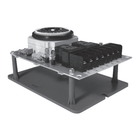
DTMV40 Series
Pressure or Time Terminated Multi-Voltage
40A Defrost Timers
WARNING
• Disconnect power at the circuit breaker(s) or disconnect switch(es) before beginning
installation or servicing.
• More than one circuit breaker or disconnect switch may be required to de-energize the
equipment before servicing.
• Do not use the manual off position of the timer for equipment servicing. Always discon-
nect the power at the circuit breaker(s) or disconnect switch(es).
• Use COPPER conductors ONLY.
• For 40 amp loads, use #8 AWG wire, rated 90˚C min.
• Wire in accordance with national and local electrical code requirements.
CAUTION
• Rotate timer dial clockwise only.
UL TYPE 3R Enclosure
STARTUP PROCEDURE
1. Determine model to be replaced (Grasslin or Competitors)
from table below.
2. Set Mode Selection (S1 BLUE DIP Switch
– Fig. A) See table below and instructions
on page 5.
3. Apply corresponding Terminal
Identification and Door labels –see retrofit
kit instructions.
4. Set correct input voltage (S2 RED DIP
Switch – Fig. B).
5. Follow installation and programming instructions.
The DTMV40 can be configured for
either 120 or 208/240VAC. Locate RED
DIP Switch to the right of timer module.
For:
• 120VAC slide DIP switch UP
• 208/240VAC slide DIP switch DOWN
Paragon
Precision
TIME INITIATED, TIME TERMINATED
TIME INITIATED, REMOTE TEMPERATURE OR
PRESSURE TERMINATED
TIME INITIATED, PRESSURE TERMINATED
(Separate Pressure Switch Required (see instructions)
Grasslin
Time Initiated, Temperature,
Risk of Fire or Electric Shock
Risk of Damage to Timer
Input Voltage Switch (S2)
Mode Selection Switch (S1)
Bracket Mount
Mode Selection
Wiring Diag.
INSTALLATION
Note: For outdoor locations, raintight, or wet location conduit
hubs that comply with requirements of UL 514B (standard for
fittings for conduit and outlet boxes) are to be used.
1. Open door and then remove interior protective cover by
releasing spring clip on bottom.
2. Remove timer mechanism by releasing spring clip on bot-
tom.
3. Select knockouts to be used. Remove inner 1/2" knockout
by inserting a screwdriver in the slot and carefully punch
knockout loose. Remove slug. If 3/4" knockout is required,
remove the outer ring with pliers after removing the 1/2"
knockout. Smooth edges with knife if necessary.
4. Place enclosure in desired mounting location and mark the
three mounting holes (refer to diagram below). Start by
placing set screw on top and attaching enclosure over
keyhole: then screw in remaining two screws on bottom.
5. Connect conduit hubs to conduit before connecting the
hubs to the enclosure. After inserting hubs into enclosure,
carefully tighten hub lock nut. Do not over-torque.
6. Verify voltage selection. 120VAC – position switch UP;
208/240VAC – position switch DOWN (refer to Fig. B).
7. Wire in accordance with National and Local Codes.
8. Grounding: Terminate all ground wires to ground lug on
bottom of enclosure.
9. Replace interior pro-
tective cover.
6-1/8"
2-1/2"
Ground Lug
1
Interior
Protective
Cover
Step 1
TImer Mechanism
Step 2
Advertisement

Related Manuals for Grasslin DTMV40 Series


Summary of Contents for Grasslin DTMV40 Series
- Page 1 1/2” STARTUP PROCEDURE knockout. Smooth edges with knife if necessary. 1. Determine model to be replaced (Grasslin or Competitors) 4. Place enclosure in desired mounting location and mark the from table below.
-
Page 2: Model Designation
Model Designation Models Enclosure Mount DTMV40 24-hour, Outdoor UL TYPE 3R Enclosure DTQMV40 24-hour w/Battery Backup, Outdoor UL TYPE 3R Enclosure DTMV40-IM 24-hour, Indoor Metal UL TYPE 1 Enclosure Models Non-Enclosure Mount DTMV40-M 24-hour, Mechanism Only DTQMV40-M 24-hour w/Battery Backup, Mechanism Only DTMV40-P 24-hour, Panel Mount DTMV40-B... - Page 3 DTMV40 - TYPICAL WIRING DIAGRAMS All switch positions are shown in refrigeration cycle operation, and change position upon initiation of a defrost. 8043 Replacement 8045 Replacement 8041 Replacement Mode B with 8043 Label Applied Mode A with 8045 Label Applied Mode A with 8041 Label Applied TIMER RELEASE...
-
Page 5: Terminal Identification
Xp and p of the DTMV40 (with an 8240 series ter- First determine what model is being replaced (Grasslin or minal label applied). There must be no external voltage Competitors). - Page 6 SHIPPING WEIGHT: 3 lbs. AGENCY APPROVALS: UL LISTED Furnish and install a Grasslin DTMV40 defrost control which is eld adjustable for 120V or 240V operation and shall have defrost initiation times settable to the quarter hour via captive trippers at 15 minute intervals.
Need help?
Do you have a question about the DTMV40 Series and is the answer not in the manual?
Questions and answers