Advertisement
Available languages
Available languages
Quick Links
PRODUCT DESCRIPTIONS:
These instructions cover the following FloTech products:
FT520
Optic System Tester
FT521
API Compatible Optic Test Plug
FT522
Scully Pattern Optic Test Plug
FT523
J560 Optic Test Plug
PRODUCT DESCRIPTION:
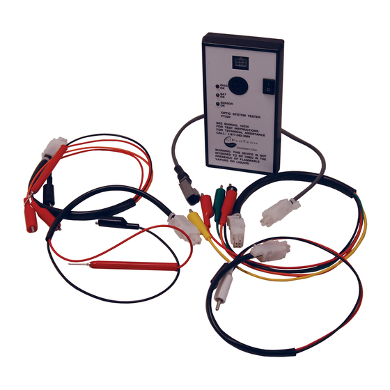
FloTech model FT520 Optic System Tester is designed to test 5 wire optic sensors and
thermistor and optic outputs from FloTech, Civacon, and Scully onboard monitors. The
FT520 is supplied with five test lead sets.
1) A five-wire test lead set to test all five wire optic sensors and optic output connections to
optic sockets.
2) A three wire test lead set with probe to test thermistor outputs to thermistor sockets.
3) A two wire test lead set with white and black boots for testing two wire sensors and optic
sockets.
4) A two wire test lead set with a probe to test for a good pulse signal through a string of five
wire sensors.
5) A plug and play test lead set for testing FloTech plug and play probes.
NOTE: Note this monitor is not intended to be used in a hazardous area. Do not use near
flammable liquids or vapors. Keep all man hole lids, vents and API valves closed when
testing a tank.
MONITOR FUNCTIONS:
The FT520 operates on 2 (two) 9v transistor batteries. Batteries are supplied with the tester
but will require changing from time to time depending on use. Do not leave the unit on
overnight, as this will deplete the batteries. Batteries are located behind a door on the back of
the tester.
NOTE: Do not change the batteries in a hazardous location. This could generate a spark
Figure 1 shows the front control panel and identifies each operator. The ON/OFF switch turns
power on and off to the unit. Note the O & I indicators on the switch. O is the off position
and I is the on position. When the ON/OFF switch is turned on a YELLOW LED should light.
This Yellow LED indicates the batteries are in good condition and the tester is sending pulses
to the sensor under test. If the Yellow LED does not light then the batteries need to be
replaced.
Rev: January 2010
Instruction Manual 10234
and cause a hazardous condition.
FT520 Optic System Tester
Page 1 of 7
Advertisement

Subscribe to Our Youtube Channel
Related Manuals for FloTech FT520

Summary of Contents for FloTech FT520
-
Page 1: Instruction Manual
J560 Optic Test Plug PRODUCT DESCRIPTION: FloTech model FT520 Optic System Tester is designed to test 5 wire optic sensors and thermistor and optic outputs from FloTech, Civacon, and Scully onboard monitors. The FT520 is supplied with five test lead sets. - Page 2 USING THE FT520 OPTIC SYSTEM TESTER: Look below for the type of test you wish to perform. Follow the directions as written. TESTING A FIVE WIRE OPTIC SENSOR: Follow this test procedure if you suspect a sensor is defective.
- Page 3 H) Retest the optic output as described in C thru F. If still bad the monitor optic output is defective and the onboard monitor block must be replaced. Contact your local FloTech / Bayco distributor for quality replacement parts.
- Page 4 FINDING A DEFECTIVE SENSOR IN A OPTIC SYSTEM WITH NO ONBOARD MONITOR: A) This test requires two FT520 testers or a rack monitor to energize the optic system. One tester is used to energize the string of sensors and one tester is used to find the defect.
- Page 5 LED is not lit continue with testing procedure. C) Connect two-wire test lead set to FT520 tester and turn on the power switch. D) Connect the black lead to the onboard monitor housing. And touch the probe to the yellow terminal where the sensors are wired to the monitor.
- Page 6 This procedure will test 6 wire FloTech, Scully, or Civacon electronic thermistor dummy using the FloTech FT520 tester. A) Plug the thermistor output test lead set into the FT520 Optic System Tester. This is the test lead set with three clip lead (RED, ORANGE, BLACK) and a RED probe.
- Page 7 Figure 1 Tester operation NEED TECHNICAL ASSISTANCE? Call FloTech Inc. at 1 877 582 3569 Bayco/FloTech order line: 1 800 355 1991 US & CANADA Rev: January 2010 Page 7 of 7...
- Page 8 FloTech Testeur pour système optique FT520 Description des produits : Ces instructions sont pour les produits FloTech suivants : FT520 Testeur pour système optique FT521 Prise de test optique API compatible pour testeur FT522 Prise de test optique à modèle Scully pour testeur...
- Page 9 FONCTIONS DU MONITEUR: Le FT520 fonctionne avec 2 batteries de 9v. Les batteries sont incluses avec le testeur mais elles devront être remplacées de temps en temps. Ne laissez pas le testeur allumé du jour au lendemain sinon les batteries se déchargeront.
- Page 10 UTILISER LE TESTEUR À SYSTEM OPTIQUE FT520: Regardez ci-dessous pour voir le genre de tests que vous voulez performer. Suivez les instructions suivantes.
- Page 11 TROUVER UN CAPTEUR DÉFECTUEUX SUR UN SYSTÈME OPTIQUE SANS MONITEUR INTÉGRÉ : A) Ce test exige deux testeurs pour FT520. Un testeur est utilisé pour alimenter les capteurs en séries et l’autre testeur est utilisé pour trouver des défaillances. (un moniteur à rampe de...
- Page 12 Voir étape G. G) Prenez le deuxième testeur FT520 et connectez le cordon testeur à 2 brins. (Jeu de pointe de pointe & pince crocodile; avec le cordon testeur à deux brins, le testeur agi comme un détecteur de pulsation).
- Page 13 (couverture noir) au brin rouge du capteur et le cordon testeur noir (couverture blanche) au brin noir du capteur. C) Allumer le testeur. Le testeur FT520 devrait avoir une tonalité continue. D) Si le capteur est défectueux le capteur ne sonnera pas l’alarme Sonalert ou allumer l’indicateur LED vert.
- Page 14 A) Branchez le cordon testeur pour signaux de thermistance de sortie dans le système optique d’essai FT520. Ceci est l’ensemble du cordon testeur à 4 brins, 3 brins ont des pinces crocodile (rouge, orange, noire) et un pointe de touche rouge.
- Page 15 E) Appuyez le jeu de pointe de touche ROUGE sur le brin ROUGE du « dummy » et une tonalité sonore continue du testeur FT520 devrait être entendu. F) Attachez la pince crocodile ROUGE sur le brin NOIR du « dummy ». Appuyez le jeu de pointe de touche ROUGE sur le brin NOIR du «...
- Page 16 Figure 1 Opération de test BESOIN D’ASSISTANCE TECHNIQUE? Appelez FloTech Inc. au 1 877 582 3569 Dixon/FloTech lignes de service: 1 800 355 1991 E-U ET CANADA 10234(fr)Rev: January 2010...
Need help?
Do you have a question about the FT520 and is the answer not in the manual?
Questions and answers