Table of Contents
Advertisement
Advertisement
Table of Contents

Summary of Contents for Molift Quick Raiser 205
- Page 1 Molift Quick Raiser 205 EN - User manual BM13001 Rev. C 2018-01-08...
-
Page 2: Table Of Contents
Hand control ..........8 before attempting to use the Checklist after installation .......8 equipment. Reset service indicator ......8 How to use Molift Quick Raiser 205 ...9 Before use / Daily check ......9 Hand control ..........9 Safety devices ........10 Steering handles ........10 Brakes ..........10... -
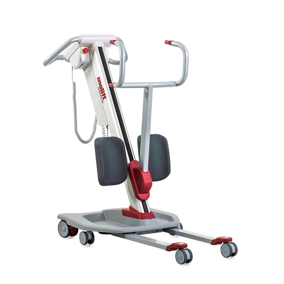
Page 3: Molift Quick Raiser 205
It has electrically adjustable legs and a sling. Molift Quick Raiser 205 is intended for with a lifting capacity of 205 kg (451lbs). users who can follow instructions, have good... -
Page 4: General
Modifications and use of components made by other manufacturers. We recommend only using Etac Molift components and spare parts. Declaration of conformity is not valid and Etac is not responsible for warranty if any modifications are made to the product. Etac shall not be liable for faults or accidents that can occur when using components made by other manufacturers. -
Page 5: Technical Data
Molift QuickRaiser 205 Technical Data Quick Raiser 205 Safe Working Load (SWL): 205 kg (451 lbs) Weight of unit: 922 mm 922 mm (36 / in) Total weight of unit: 44,5 kg/98 lbs (36 / in) Chassis: 17 kg/37,5 lbs... -
Page 6: Assembly
Molift QuickRaiser 205 Assembly Instructions Before assembly 1 - Battery Push in the emergency stop button before Locate assembly tools (5mm allen key, and 17mm assembly spanner) Place the column on a horizontal surface. Make sure the emergency stop is pushed in. -
Page 7: Leg Support
Turn the lifter over on the side. Insert screw and washer in the top hole and tighten the screw. Connect cable between column and chassis. (NB! The cable is NOT applicable with the Molift Quick Raiser 205 FL version) The screws will ensure that the column cannot be pulled upwards. -
Page 8: Lifting Arm
Molift QuickRaiser 205 4 - Lifting Arm 5 - Mains cable Place the cover onto the lifting arm. Place lifting arm in trolley, and insert the bolt. Connect the mains cable to the bottom of the battery box. Insert the bolt and tighten the screw using the 17mm spanner and an 6mm allen key. -
Page 9: Hand Control
Molift QuickRaiser 205 6 - Hand control Reset service indicator If the service LED is yellow, please contact your Molift service partner regarding the necessary measures. Service indicator will start to be yellow again when 12 months has passed and it is time for periodic inspection. -
Page 10: How To Use Molift Quick Raiser 205
Working pause ratio/Duty Cycle. body support unit, then the lowest maximum load shall always be used Molift Quick Raiser 205 should not be run con- stantly for more than 2 minutes (with maximum Molift lifters shall only be used to load), and rest for minimum 18 minutes. -
Page 11: Safety Devices
Molift QuickRaiser 205 Safety devices Molift Quick Raiser 205 is equipped with several safety devices, which are intended to prevent injury to personnel or damage to the equipment in the case of incorrect use or failure The lifter has an overload sensor preventing the lifter to be operated if the load exceeds SWL. -
Page 12: Electronics
Green 80 - 60% Battery Green 60 - 40% Molift Quick Raiser 205 is available with a 24V SLA battery or a 25.6V LiFePO4 battery - both with an Green 40 - 20% integrated charger. The SLA battery has a life expectancy of approx. -
Page 13: Charging
Molift QuickRaiser 205 Service indicator Do not position lifter in a way The lifters electronics record the weight lifted and that makes it difficult to discon- number of lifts. After a certain period of operation nect mains cable a signal is given to indicate that service is required. -
Page 14: Transfer
180 degrees to increase sup- port on both inside or outside of the users legs. Move the Quick Raiser 205 in front of the user. Place the feet on the footplate. If necessary - help the user to place the feet correctly. Lock the wheels on the lifter before lifting the user. -
Page 15: Using A 4-Point Lifting Arm
Molift QuickRaiser 205 Using a 4-point suspension Using a 2-point suspension Fasten the sling to the lifting arm by guiding the strap into all 4 hooks. On the 2-point suspension arm the ropes is attached to the lifting arm by pulling them firmly from above and into the rope locks. -
Page 16: Raising
Molift QuickRaiser 205 Raising/Lowering Transfer When moving the user, stand to the side of the Raise the patient carefully until the buttocks are person you are lifting. Make sure that arms and clear from the seating and tighten the belt. Unlock legs do not obstruct the seat, bed, etc. -
Page 17: Accessories
Molift QuickRaiser 205 Accessories Lifting arms and slings (Recommended) optional equipment and acces- sories for Molift Quick Raiser 205. 4-point suspension: Accessories Quick Raiser Active lifting arm Extension for power cord Art. no.: 2910060 Art. no.: 2920117 Set of inlay for footplate Art. -
Page 18: Maintenance
When performing a periodic inspection, the inspector shall fill out the inspection report for Periodic inspection is a visual examination (particu- Molift Quick Raiser 205. The reports should be larly of the lifter’s load bearing structure and lifting retained by the person(s) responsible for servicing mechanism with attachments, brakes, controls, the lifter. -
Page 19: Troubleshooting
Molift QuickRaiser 205 Troubleshooting Symptom Possible Cause/Action The lifting column is wobbly Locking bolts are not properly secured or lifting column is not properly in place in the chassis / check if the column is correctly placed in the chas-...
Need help?
Do you have a question about the Quick Raiser 205 and is the answer not in the manual?
Questions and answers