Table of Contents
Advertisement
Advertisement
Table of Contents

Related Manuals for Assoma AM Series

Summary of Contents for Assoma AM Series
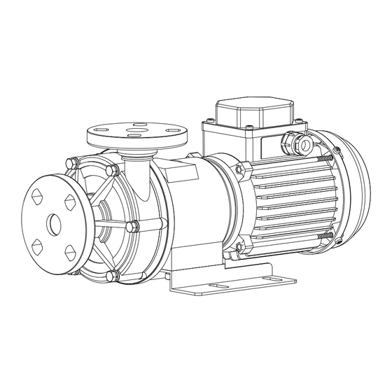
- Page 1 User Manual Seal-less Magnetic Drive Pump AM Series...
-
Page 2: Table Of Contents
This manual references the following safety symbols: Failure to follow these instruction(s) would most certainly result in serious bodily injury or death. Failure to follow these instruction(s) could result in serious bodily injury or death. Failure to follow these instruction(s) could result in bodily injury and/or equipment damage. -
Page 3: Foreword
1. Foreword Thank you for purchasing an ASSOMA pump. To ensure proper operation and maximum efficiency, please read this instruction manual carefully. Failure to follow the recommended operating instructions outlined in this manual may result in serious personal injuries and/or equipment damage. -
Page 4: Installation, Piping, And Wiring
The “Head” refers to “Total Head”, defined as such: This pump is designed and manufactured according to specifications agreed upon between ASSOMA and the customer. Such specifications include but are not limited to the following: chemical composition, operating temperature, working pressure, environmental factors, and other operating conditions. - Page 5 Make sure no one is within proximity of the pump while lifting or transporting. Please consult with your ASSOMA representative, authorized distributor or agent if the pump is to be installed under any of the following environments: (1) Potentially explosive gas, dust or material is present.
- Page 6 4.3 Notes for Installing the Piping System 1.Outlet Piping 2.Throttle Valve Air Pocket 3.Priming Piping 4.Priming Valve 5.Check Valve 6.Outlet Pressure Gauge 7.Motor 8.Pump 9.Inlet Pressure Gauge 10.Inlet Piping 11.Inlet Piping Support 10 11 12.Vibration Damper Good 0.01~0.02 slope 13.Filter 14.Inlet Tank 15.Foot Valve Fig.
- Page 7 Component Installation Notes piping the closest tank wall to prevent circulation (see Fig. 4.4). (2) The submerge depth of the suction pipe inlet should be at least 0.5m or at least 2D below the liquid surface (see Fig. 4.4). (3) There should be a distance of at least 1.5D between the bottom of the tank and the suction pipe inlet (see Fig.
- Page 8 Component Installation Notes (4) Two or more pumps installed in parallel, sharing the same discharge piping. (5) Water hammer may occur when the power is unexpectedly disrupted. Control (1) A control valve may be installed to control the flow rate. Do not run the valve pump with the control valve closed for an extended period of time.
-
Page 9: Operating Notes
Allow the pump to cool for at least one hour before priming the pump for operation. (3) A dry-run protector is recommended to detect dry-running and stop the pump to prevent pump damage. Contact your ASSOMA representative, authorized distributor or agent for more details. 5.2 Operating Temperature (1) Operating temperature may affect the chemicals viscosity, vapor pressure, and corrosiveness. - Page 10 (2) If the chemical concentration is to change, the specific gravity, and viscosity will change, affecting the shaft power, capacity, and head. Therefore, please check with your ASSOMA representative, authorized distributor or agent to make sure the pump is suitable for the new application.
-
Page 11: Operating Procedure And Notes
6. Operating Procedure and Notes 6.1 Before Start-Up (1) Check the power supply (frequency, voltage, and wiring). (2) Double-check to make sure all screws (flange, casing, base plate, etc.) are securely fastened. (3) Perform priming and make sure all air are removed from the pump casing and suction piping. -
Page 12: Maintenance And Inspection
※ Thrust Rings (2) Cracks (2) Replace Motor (1) Phase resistance and insulation (1) Repair if abnormal impedance (2) Check bearing lubricant if using open (2) Maintain proper lubrication bearings ※ Contact your ASSOMA representative, authorized distributor or agent. 10... - Page 13 The O-Rings should be replaced even if they don’t display any signs of corrosion or deformation. Prolonged use may reduce the elasticity of the O-Rings, resulting in future failure. 7.3 Replacement Limits and Recommendations for Wear Parts Table 7.3 Replacement Limits for Wear Parts Unit: mm Dimension Model...
-
Page 14: Improper Pump Usage
(2) Modification: Modifying the pump could result in equipment damage, electric shock or personal injuries. Do not attempt to modify the pump. Contact your ASSOMA representative, authorized distributor or agent for advice if the pump no longer meets your operational needs. - Page 15 Abnormal Use Condition Potential Damage or Symptom Improper parallel pump design Pump with worse suction condition or both pumps: (1) Reduced performance, resulting in low flow rate (2) Severe cases may result in dry-running Leaking foot valve or leaking Loss of liquid within pump during shut-down, resulting in suction dry-running when pump is restarted Improper Priming...
-
Page 16: Repair And Warranty
When a problem arises, please use this manual for initial troubleshooting. If the issue cannot be found or if pump or motor is suspected to be damaged, contact your ASSOMA representative, authorized distributor or agent for further instructions. Have the following... -
Page 17: Annex A. Am-Series Exploded View And Parts List
Annex A. AM-Series Exploded View and Parts List Part No. Part Name Part No. Part Name 723.01 Inlet Flange Impeller 412+NO. O-Ring 314.02 Rear Thrust Ring Pump Casing Rear Casing 723.02 Outlet Flange Drive Magnet 314.01 Front Thrust Ring Bracket Shaft Base Bearing... -
Page 18: Annex B. Description Of Atex-Specific Marking
Annex B. Description of ATEX-Specific Marking (1) The ATEX-specific marking of this pump (without motor) is described below. (2) Please refer to the motor name plate for the motor’s ATEX marking. Pump ATEX Mark: II 2 G c IIA T4 Distinctive Community mark Equipment group: All except for underground mines Equipment category: For equipment providing a high level of protection when used...
Need help?
Do you have a question about the AM Series and is the answer not in the manual?
Questions and answers