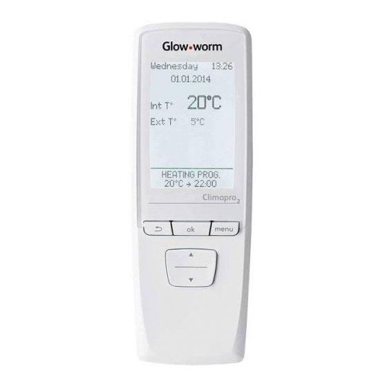
Glow-worm Climapro2 RF Installation Manual
Hide thumbs
Also See for Climapro2 RF:
- Installation manual (24 pages) ,
- Instructions for use manual (12 pages)
Table of Contents
Advertisement
Quick Links
Advertisement
Table of Contents

Summary of Contents for Glow-worm Climapro2 RF
- Page 1 Installation Climapro...
-
Page 3: Instructions Guidance
RF must only be installed by a qualifi ed professional who is responsible ATTENTION: Risk of damage to for compliance with the standards and Climapro RF or to its vicinity. regulations in force. IMPORTANT: Useful information. - 3 - 0020094584_02 - 06/11 - Glow-worm... - Page 4 • Take the unit to an appropriate collection point for processing, energy recovery and recycling of waste. By complying with this directive, you will contribute to the preservation of natural resources and the protection of human health. - 4 - 0020094584_02 - 06/11 - Glow-worm...
-
Page 5: Installation
- near air currents that may come from - Radio Receiver doors or windows. - Packet containing 2 fi xing screws with rawlplugs - 4 “AA LR6 « alkaline batteries - EBUS cable for radio receiver - 5 - 0020094584_02 - 06/11 - Glow-worm... - Page 6 Location of radio receiver • Insert the plugs (5) in the holes (1). • Secure (B) the room thermostat support (4) with screws (2). • Slide the room thermostat (6) into its support (4). - 6 - 0020094584_02 - 06/11 - Glow-worm...
-
Page 7: Electrical Connections
The radio receiver must be connected via an EBUS connector. Main board Connecter Electrical wires Insulation When you connect electrical wires on a connector on the electronic board: - 7 - 0020094584_02 - 06/11 - Glow-worm... - Page 8 • Open (A) the access for the 24 V connection (1). • Cut (B) the pre-cut part (3) of the control box unit (2). • Remove (C) the pre-cut part of the control box unit (2). - 8 - 0020094584_02 - 06/11 - Glow-worm...
- Page 9 Case n°3 - radio receiver outside the appliance The radio receiver can be paired with the wireless outdoor sensor (see the outdoor sensor installation manual). Ebus and 0V connection Cable strain relief Connector for the radio receiver - 9 - 0020094584_02 - 06/11 - Glow-worm...
- Page 10 Show or hide the cooling screen. function in the end user 10.1 Functions menu. Showing, enabling and Enable or disable the cooling disabling of functions is program. refl ected in the user menu. - 10 - 0020094584_02 - 06/11 - Glow-worm...
- Page 11 - remind the user to service the appliance signal (thermostat and wireless outdoor sensor). annually. • To exit the installer menu press button for 3 seconds or until the main screen is displayed. - 11 - 0020094584_02 - 06/11 - Glow-worm...
-
Page 12: Maintenance
After Sales Service. You will fi nd a list of certain error in the user manual. Legend Radio receiver Radio receiver cover Red LED Radio receiver circuit board Green LED - 12 - 0020094584_02 - 06/11 - Glow-worm... - Page 13 - the batteries are not dead. If so, replace them with - Defective EBUS connection new batteries. cable • Check the electrical connection between the radio receiver and the appliance. • Check the radio communication between the thermostat and the receiver. - 13 - 0020094584_02 - 06/11 - Glow-worm...
-
Page 14: Technical Data
Average range within the home (*) (*) Depends on the installation’s conditions and the electromagnetic environment. Radio receiver EBUS power supply Electrical connection cable section mm² 2 x 0.75 Max. length of electric connection cables - 14 - 0020094584_02 - 06/11 - Glow-worm... - Page 16 GLOW-WORM Nottingham Road, Because of our constant endeavour for Belper, Derbyshire. improvement, details may vary slightly DE56 1JT from those shown in these instructions. www.glow-worm.co.uk...


Need help?
Do you have a question about the Climapro2 RF and is the answer not in the manual?
Questions and answers