Advertisement
N
ETWORK
Comm Activity
®
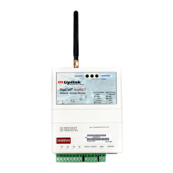
DigiCell
Any NET
Network Access Module
Input 1 Standard S3 off, S4 off
Input 1 Pulse Ctr S3 off, S4 on
Input 1 Timed Bell S3 on, S4 off
S/N
19-25133-070
IN1
IN2
IN3
IN4
OUTPUT 1 OUTPUT 2
+
-
+
-
+
-
+
-
D
C
IGI
A
Product ID # 19-25133-040/-041
I
NSTALLATION AND
Network Status
Service
Network Interface Network Service
AMPS
Cellemetry
GSM
SMS
CDMA
GPRS
Ethernet
1xRTT
TCP/IP
RS-232
Input 1 Sampled Siren S3 on, S4 on
9200920999
307V100B
12VDC
+
-
ELL
®
CCESS
U
SER
®
A
NET
NY
M
ODULE
'
G
S
UIDE
Advertisement

Summary of Contents for Uplink DigiCell AnyNET
- Page 1 Comm Activity Network Status Service ® DigiCell Any NET Network Access Module Network Interface Network Service ® AMPS Cellemetry CDMA GPRS Ethernet 1xRTT TCP/IP RS-232 Input 1 Standard S3 off, S4 off Input 1 Sampled Siren S3 on, S4 on Input 1 Pulse Ctr S3 off, S4 on Input 1 Timed Bell S3 on, S4 off 9200920999...
- Page 2 Numerex reserves the right to make changes to any software or product to improve reliability, function or design. Uplink is a servicemark, DigiCell and Cellemetry are registered trademarks of Numerex Corp. Other product names mentioned in this manual may be trademarks or registered trademarks of their respective companies and are hereby acknowledged.
-
Page 4: Table Of Contents
ABLE OF ONTENTS Warranty Information & Liability Waiver ..... 1 Technical Support ............2 Description ..............3 Installation Steps ............4 Unit Wiring ..............6 Optional DB25 Connector ..........9 Antenna Specification ..........9 FCC & Industry Canada Regulatory Compliance ..10... -
Page 6: Warranty Information & Liability Waiver
& L ARRANTY NFORMATION IABILITY AIVER The Company's Products Are Subject To The Following Limited Warranty: The company's products are warranted against defects in materials and workmanship for a period of one (1) year following the date of purchase, under normal use and ser- vice. -
Page 7: Technical Support
Login name • Password • Serial number of the unit These items are required in order to assist you. UPLINK Technical Support 1600 Parkwood Circle, Suite 500 Atlanta, GA 30339 888-9-Uplink Fax: 770-693-3501 For Customer Support, call 888-987-5465, or visit www.uplink.com... -
Page 8: Description
ESCRIPTION ® DigiCell AnyNET Network Access Modules are comprised of various radio modules support- ing multiple digital radio technologies. Supported technologies include GSM and CMDA. Supported services include SMS for either GSM or CDMA. Support is also provided for expansion to broadband wireless. In addition, a variant of this Module can be configured with an IP communications module providing 10/100 Ethernet connectivity. -
Page 9: Installation Steps
For new customers, establish an account with Uplink by visiting the www.uplink.com website and requesting a new account. The AnyNET Module must be activated and configured from the Uplink website at www.uplink.com or by calling Uplink Support at 1-888-987-5465. Install the Module’s antenna on top of the unit. - Page 10 The AnyNET Module is configured via the DIP switches on the front panel. Figure 1: Detail of Dip Switch Set DIP switches according to the following table: Switch# Settings reserved (set to off) reserved (set to off) S3 and S4 Input 1 Type Standard Input Pulse Counter...
-
Page 11: Unit Wiring
IRING The location of the DIP switch, terminal block connections, network port, serial interface, and status LEDs of the Module are shown in Figure 2 on page 5. Further detailed drawings included below. OUTPUT1 OUTPUT2 12VDC Figure 3: Detail of connections Input 1 (Selectable Via DIP Switches) Standard Input - (DIP switches S3 OFF, S4 OFF) This mode configures the unit to be tripped from a DC voltage ranging from 9 VDC to 12 VDC or an open collector. - Page 12 Figure 4: Wiring example for voltage trip Voltage Trip - Inputs 2, 3, and 4 (and 1 if set for standard input) can be tripped by applying 12 V to the + input and 0 V to the - input. A signal must be continuously present for 500 ms. INPUT –...
- Page 13 You need to assemble your serial connection cable as detailed in the graphic below. Pinouts on this connector are as follows: Pin 1 Pin 2 Data to Unit Pin 3 Data From Unit Pin 4 Ground Figure 6: Serial connector details The serial communications protocol document is available upon request.
-
Page 14: Optional Db25 Connector
DB25 C PTIONAL ONNECTOR The unit may be optionally configured with a DB25 connector in place of terminal block con- nections. Figure 7: Optional DB25 Connector Pinouts on this connector are as follows: Signal Notes Signal Notes Case Ground Power Ground +5V/+12V Supply/Battery Rtn TXD - Data In Serial Data Input Power Ground +5V/+12V Supply/Battery Rtn... -
Page 15: Fcc & Industry Canada Regulatory Compliance
FCC & I NDUSTRY ANADA EGULATORY OMPLIANCE This device complies with Part 15 of the FCC Rules. Operation is subject to the fol- lowing two conditions: (1) this device may not cause harmful interference, and (2) this device must accept any interference received, including interference that may cause undesired operation. - Page 16 Numerex Corp www.nmrx.com (770) 693-5950 1600 Parkwood Cir SE Suite 500 Atlanta, GA 30339...
Need help?
Do you have a question about the DigiCell AnyNET and is the answer not in the manual?
Questions and answers