Advertisement
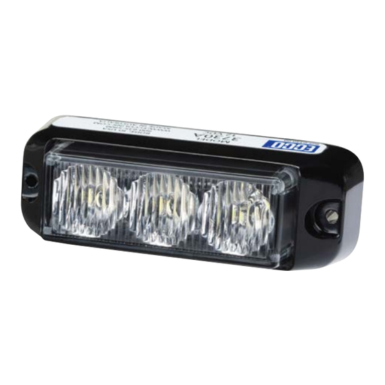
3730 series LED heads are compact yet versatile high intensi-
ty directional LED warning lights suitable for mounting any-
where on a vehicle. Colorless until illuminated, these discrete
LED heads feature urethane encapsulated electronics offering
a high degree of environmental and vibration protection.
Additional benefits of these LED lights include low current
draw, a long and maintenance free service life with reliable
solid-state operation and extremely low electromagnetic emis-
sions. These LED heads feature 12-24V operation, multiple
user-selectable flash patterns and synchronization capability.
!
WARNING!
Failure to install or use this product according to manufacturers recommendations may result in property
damage, serious bodily/personal injury, and/or death to you and those you are seeking to protect!
Do not install and/or operate this safety product unless you have read and understand the
safety information contained in this manual.
1. Proper installation combined with operator training in the use, care, and maintenance of emergency warning devices are
essential to ensure the safety of you and those you are seeking to protect.
2. Exercise caution when working with live electrical connections.
3. This product must be properly grounded. Inadequate grounding and/or shorting of electrical connections can cause high
current arcing, which can cause personal injury and/or severe vehicle damage, including fire.
4. Proper placement and installation are vital to the performance of this warning device. Install this product so that output
performance of the system is maximized and the controls are placed within convenient reach of the operator so that s/he
can operate the system without losing eye contact with the roadway.
5. It is the responsibility of the vehicle operator to ensure during use that all features of this product work correctly. In use, the
vehicle operator should ensure the projection of the warning signal is not blocked by vehicle components (i.e., open trunks
or compartment doors), people, vehicles, or other obstructions.
6. The use of this or any other warning device does not ensure all drivers can or will observe or react to a warning signal.
Never take the right-of-way for granted. It is your responsibility to be sure you can proceed safely before entering an
intersection, driving against traffic, responding at a high rate of speed, or walking on or around traffic lanes.
7. This equipment is intended for use by authorized personnel only. The user is responsible for understanding and obeying
all laws regarding warning signal devices. Therefore, the user should check all applicable city, state, and federal laws and
regulations. The manufacturer assumes no liability for any loss resulting from the use of this warning device.
Contents:
1 x 3730 Series Surface Mount LED Head
1 x Installation and Operating Instructions
1 x Mounting gasket
2 x Front mounting screws (# 6 x 1 1/4" Self Tapping),
with washers and nuts.
Installation and Operation Instructions
3730 Series Surface Mount
Specifications:
Size:
Input Voltage:
Current Draw: Model 3730: 650mA peak
Operating temperature range:
LED Heads
3.7"[94mm] length, 1.3"[34mm] width,
1.5"[39mm] height
Model 3730: 12-24 VDC (9-32V)
-40 to +50ºC
Advertisement
Table of Contents

Subscribe to Our Youtube Channel
Summary of Contents for Ecco 3730 Series
- Page 1 Installation and Operation Instructions 3730 Series Surface Mount LED Heads 3730 series LED heads are compact yet versatile high intensi- ty directional LED warning lights suitable for mounting any- where on a vehicle. Colorless until illuminated, these discrete LED heads feature urethane encapsulated electronics offering a high degree of environmental and vibration protection.
- Page 2 LED heads – it only controls the The 3730 series LED heads should be mounted to a flat relative timing of the flash patterns (see notes surface or one with the least amount of curvature. The on page 4).
- Page 3 Mounting Brackets (Optional accessories, sold separately.) MOUNTING BRACKET Mount the 3730 on the bracket as shown in the appropriate dia- gram. Push the two 6-32 x 1-1/4 screws through the mounting holes at the front of the unit and through the holes in the rubber mounting gasket.
- Page 4 Notes on Synchronizing and Phase: Phases A and B for each style of flash pattern in the table denote the relative timing between LED heads connected in a synchronizing installation. To operate simultaneously, each LED must be set to the same phase (A + A or B + B); to operate alternately, LED heads must be set to have the opposite phase (A + B or B + A).
Need help?
Do you have a question about the 3730 Series and is the answer not in the manual?
Questions and answers