
Related Manuals for Danisense DS Series

Summary of Contents for Danisense DS Series
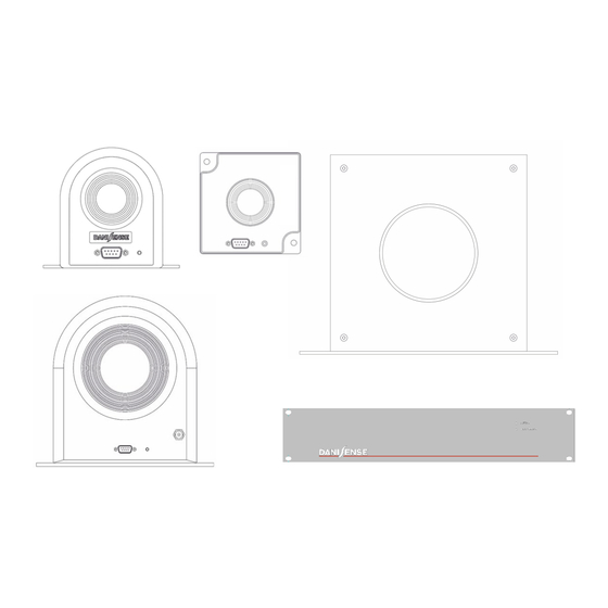
- Page 1 PRODUCT MANUAL ULTRA-STABLE HIGH PRECISION CURRENT TRANSDUCERS INTEGRATED BODY: DS, DQ, DL SERIES ■ SEPARATE HEAD TRANSDUCER SYSTEMS: DR SERIES ■ Precision - Innovation...
-
Page 2: Table Of Contents
TABLE OF CONTENTS 1. NOTICE…………………………………………………………………………. 1.1 Safety informations …………………………………………………………… 1.2 Certifications…………………………………………………………………… 2. INTEGRATED BODY TRANSDUCERS (DS, DQ, DL series)……………. 2.1 Introduction & overview……………………………………………………….. 2.2 Description……………………………………………………………………... 2.3 Installation & Operation………..……………………………………………... 2.3.1 Mounting instructions…………………………………………………. 2.3.1.1 Positive current flow…………………………………… 2.3.1.2 Fastening torques……………………………………… 2.3.2 Electrical connection instructions……………………………………. 2.3.2.1 Current output………………………………………………... -
Page 3: Notice
NOTICE 1.1 Safety information The user must have read and understood this chapter before undertaking any action with the measuring device. For all information considered inadequate, please contact the manufacturer or your lo- cal representative. Do not use the device in any manner not specified by the manufacturer. WARNING ... -
Page 4: Integrated Body Transducers (Ds, Dq, Dl Series)
Output Options Name type 300-400A 500-1000A 2000A DS300ID Standard DS50ID DS200ID DS600ID DS400ID Current Calibration DS200ID-CD100 DS600ID-CD100 Winding DS200ID-CD1000 DS Series DS300UB-1V DS600UB-1V DS50UB-1V DS200UB-1V DS300UB-10V Voltage Standard DS600UB-10V DS50UB-10V DS200UB-10V DS400UB-1V DS1000UB-10V DS400UB-10V Standard DL2000ID Current Calibration DL2000ID-CD100 DL Series... -
Page 5: Installation & Operation
DL Series DQ Series Base plate mounting 4 holes Φ 5.5 x 11 mm for 2 holes Φ 5.5mm for 4 x M5 steel screws / 6N.m 2 x M5 steel screws / 4.4N.m 2.3.2 Electrical connection instructions This chapter describes the electrical connection of the transducer according to their types of output (current or voltage). -
Page 6: Electrical Connection Instructions
2.3.1.2 Fastening torques: The devices is suitable for different fixation configurations, using the mounting plates designed for that purpose. Please respect the fastening torques indicated below to avoid damaging the device. DS Series Base plate mounting Backside panel mounting 3 tapped holes Φ 4.0 x 6H for 2 holes Φ... -
Page 7: Calibration Winding Version
2.3.2.1.2 Version with calibration winding For some applications, it’s preferable to perform a prior functional / accuracy check of the device at full scale or a fraction of full scale before apllying the power. For that purpose, a primary winding, most commonly of 100 turns or 1000 turns is added. -
Page 8: Power Supplies Interface Units
For –15VDC, I output = Ins + Is = 96 + 600 = 696mA 2.3.3.2 Multi-channels power supplies interface DSSIU series Danisense recommends the 1U rack-mount multi-channels power supplies interface DSSIU series for best performances, many useful features and options. The following table shows the different options:... -
Page 9: Connection Of Calibration Winding With Dssiu-6-1U (-V)
DSSIU-4-1U DSSIU-6-1U DSSIU-6-1U-V Mains voltage DSUB9 connector for transducer connection Banana jacks for transducer’s current output Banana jacks for calibration winding terminals Status connector Mini XLR socket for transducer’s voltage or current outputs 2.3.3.3 Connection of calibration winding with DSSIU-6-1U (or DSSIU-6-1U-V) When a device with calibration winding type - CD[n turns] is connected to the DSSIU-6-1U using the optional DSUB cable, the terminals of the calibration winding are accessible via the yellow banana sockets at the back panel of the DSSIU-6-1U (or DSSIU-6-1U-V). -
Page 10: Voltage Output Modules (Vom)
2.3.3.4 Voltage Output Modules (VOM) A voltage output module (VOM) is a PCBA containing a low drift, precision measurement resistor ) and a signal conditioning circuit which allow conversion of the device’s rated nominal current output to a 1V or 10V voltage signal. Up to 6 VOMs can be factory mounted into the 6-channel power supplies interface unit (DSSIU-6-1U-V). -
Page 11: Noises Immunity Of Voltage Output Versions
2.3.3.6 Noises immunity of voltage output versions Compared to current output devices, voltage output models are generally less immuned to induced noises from external sources. In the following schematics, two configurations are shown. Config. 1: Current transducers with voltage output (e.g. DS600UB-1V) BNC cable DS600UB-1V DSUB cable... -
Page 12: Separate Head Transducer Systems (Dr Series)
Primary current Arms Output Family Name type 1000A 2000A 5000A 10000A Current DR5000IM DR10000IM DS Series Voltage DR1000UL-10V DR2000UL-10V DR5000UX-10V/7500A DR10000UX-10V 3.2 Description DR Series < 5000A DR Series ≥ 5000A Output connector of transducer head Status connector Transducer head fixation plate... -
Page 13: Installation & Operation
3.3 Installation & Operation 3.3.1 Mounting instructions 3.3.1.1 Positive current flow: each transducer head is marked with an arrow at the side of the housing for the positive current direction, as shown below. Please respect the current flow indication to ensure that the output signal is in phase with the input signal. DR Series <5000A DR Series >=5000A Arrow symbol... -
Page 14: Electrical Connection Instructions
The control unit is rack mountable which can be mechanically fixed by using the mounting holes on the front side as shown below: DR Series <5000A DR Series ≥ 5000A 4 tapped holes Φ 8.0 x 12 4 tapped holes Φ 8.0 x 12 rack mountable, 1U high control unit rack mountable, 2U high control unit 3.3.2 Electrical connection... -
Page 15: Voltage Output
3.3.2.2 Voltage output Voltage output models (10V at rated current) are identified by the letter in their model names (e.g. DR5000UL-10V). DR Series < 5000A DR Series ≥ 5000A For DRxxxUL : 4 pins LEMO connector For DRxxxUX : 3 pins XLR mini connector ERA.2S.304.CLL XLRm /Banana Voltage Cable (2m) with shielding for better immunity is provided in... -
Page 16: Electrical Consideration
4 . ELECTRICAL CONSIDERATIONS 4.1 Common mode noises Common mode noises occur when high dV/dt in switching circuits such as inverters, switch mode power supplies etc. generates parasitic currents i circulating through stray capacitance Cs that exists between the parts of an electronic component or circuit simply because of their proximity to each other. The value of ip is determined by the following formula: = Cs x dV/dt Sensing Head... -
Page 17: Saturation Behavior
- a primary current flows in the hole of the un-powered device etc. When saturation occurs, the DS series is designed to hold the output signal high for a period up to 1 sec- ond as shown in the green color waveform below. During that period, if the overload disappears, the DS oper- ates normally. -
Page 18: Influence Of The Return Conductor
4.3 Influence of the return conductor The magnetic field from the return branch of the primary current (cable / busbar) or of any adjacent conductors (e.g. the remaining phases of a 3 phase configuration) exerts a certain influence on the sens- ing core of a fluxgate current transducer (grey area of the illustration below). -
Page 19: Derating Of External Measuring Resistor R M
7.5Ω 4.5 Frequency derating Danisense fluxgate current transducers offer extreme precision in DC and low frequency. However, they also have excellent frequency bandwidth relative to similar products in the market thanks to fast switching speed of the fluxgate excitation circuit. High frequency AC current produces heat in the magnet- ic core. -
Page 20: Measuring Large Current With Two Transducers
Consideration must be given to the value of the measuring resistor R to avoid saturation. Please consult with Danisense or your nearest local Danisense’s representative for advice. 4.7 Measuring small currents with multiple primary turns Danisense’s ultra-stable and high precision fluxgate current transducers exhibit excellent linearity error (less than a few ppm), one of the best few available in the market. -
Page 21: Advanced Sensor Protection Circuit (Aspc)
(green LED lit) before turning ON the primary circuit. DANISENSE’s fluxgate devices are equipped with an Advance Sensor Protection Circuit to provide protection of the device during transitory period. ASPC working principle and design is described below: •... -
Page 22: Definition Of Parameters
5. DEFINITION OF PARAMETERS Parameter Symbol Unit Definition Nominal primary AC current Arms Rated AC current for continuous operation PN AC Nominal primary DC current Rated DC current for continuous operation PN DC Measuring range Î Max DC current (or peak value) that can be accurately measured Max primary current without damage. -
Page 23: Product Naming Rules
CDxxx: DSUB xxx nb of calibration turns B: programmable Pxxx: peak xxx amps xV/yA: x volts 10V/B: 10V @ programmable Bulk: bulk packaging CPR: Russian version CP##: Custom reference Family name description: DP Series DC Series DQ Series DS Series DL Series DR Series 2018.09.v1_en...
Need help?
Do you have a question about the DS Series and is the answer not in the manual?
Questions and answers