
Related Manuals for Artos CR.11


Summary of Contents for Artos CR.11
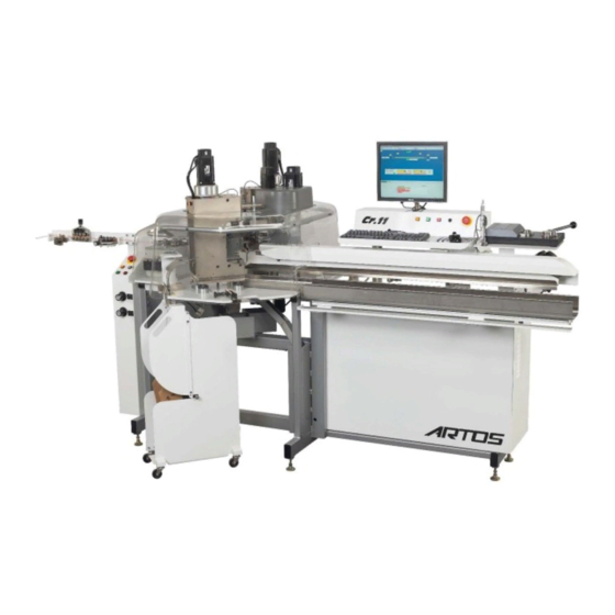
- Page 1 Machine Model CR.11/22 Dual End Processor Owner’s Manual P/N 6-119916 Rev. 7.07 Date 03 Apr 2017 For Artos Unity Version 7.00 and higher...
- Page 2 Artos Engineering Company 21605 Gateway Court Brookfield, WI 53045 Phone 262-252-4545 Fax 262-252-4544 www.artosnet.com service@artosnet.com...
-
Page 3: Table Of Contents
CUSTOMER SAFETY NOTICE ....................... 7 DANGER AREAS OF THE MACHINE ....................7 SAFETY INTERLOCKS ......................... 10 DAILY SAFETY CHECK ........................11 SAFETY WARNINGS!! ........................13 CR SPECIFICATIONS ........................14 GENERAL DESCRIPTION ......................18 LIMITS OF USE .......................... - Page 4 CREATING OR EDITING A WIRE ....................45 Wire feed tab ..........................46 Cut/Strip tab ........................... 47 Information tab ..........................49 Using the Sencor ..........................50 CREATING OR EDITING A LEAD / TAIL PROCESS ..............52 ...
- Page 5 DATA ORGANIZER ........................92 Selecting items..........................92 Copying or moving items........................ 92 Deleting items ..........................93 Using the Library for wires, instead of the current folder............... 93 DATA STORAGE .......................... 94 Data Backup ........................... 94 ...
- Page 6 CR11/22 PREVENTIVE MAINTENANCE ................... 146 Daily ..............................146 Monthly ............................. 147 Quarterly ............................149 Annually ............................151 CHECKING THE CR CALIBRATION ..................156 STRIP BLADE CALIBRATION ....................159 REFERENCE POSITIONS ......................159 MOTOR AND BELT REPLACEMENT ....................
-
Page 7: Customer Safety Notice
CUSTOMER SAFETY NOTICE The CR 11/22 as supplied to you must only be used with all the guards and safety devices in place and secure to meet the intended requirements. The safety interlocks must not be tampered with or overridden in any way. Should any guards, interlock, or other safety device be found to be damaged or non-operative the machine cannot be used until appropriate repairs have been effected. - Page 8 Crimping Unit – Never place your fingers in the terminal applicator. If it is necessary to remove debris use a screwdriver or similar tool. Wire pick and place device – Never place your fingers in the gripper. Seal Applicator – Never place fingers inside the frame of the seal applicator.
- Page 9 Solder pot – Never touch the solder pot, severe burns will result. Always wear eye / face protection and high temperature gloves when servicing the solder pot. Wire twister. – Never touch the rotating head of the twister. BD-4 burning device – Never the touch the heated blades, severe burns will result...
-
Page 10: Safety Interlocks
Laser stripper – Never run the laser stripper without the main guard in position. If the unit is being serviced and test are being run, always wear Laser safety glasses. SAFETY INTERLOCKS All safety guards and interlocks should be tested daily or at the beginning of each shift change. It is recommended that these checks be documented. -
Page 11: Daily Safety Check
EMERGENCY STOP BUTTONS: E-Stop Emergency Stop buttons are located at both of the operation stations. When depressed the machine will not run. Pressing the Master Start will cause a message to be displayed indicating which button is depressed. To release the Emergency Stop, rotate the button clockwise slightly. - Page 12 5. Master start the machine. Open the guard. a. The message “Hood-guard is open” will appear on the screen b. The orange master start lights turn off on machine operator stations and on the back of each crimping unit. c. The air pressure gauges on the front of the machine go to 0 d.
-
Page 13: Safety Warnings
SAFETY WARNINGS!! The following explicit directions apply in this manual. Do not disregard these directions. WARNING: personal injury may occur-Do not disregard. CAUTION: Equipment damage may occur. NOTE: Inconvenience only if disregarded. No immediate danger, damage or personal injury. WARNING!! The CR 11/22 Uses sharp cutting tools to perform its function. Great care must be taken to protect the operator and others from harm. -
Page 14: Cr Specifications
CR Specifications CR11 Machine Dimensions Inches Length with straightener bar 2670 Width with carts 1370 Height (Guard down) 1664 66.5 Height (Guard Up) 2235 Machine Weight 737 Kg 1625 lbs CR22 Machine Dimensions Length with straightener bar 3679 Width with carts 1346 Height (Guard down) 1664... - Page 15 Wire Range 0.05mm 30 AWG 4.0mm 12 AWG 0.210 In. Note: Additional sizes may be possible, see Artos for Details Wire Length 25 mm (1 inch) depending on strip length 100m 3938 inches Stripping Lengths Min. 0.1mm 0.004 in...
- Page 16 Typical Nameplate 21605 Gateway Ct. Brookfield, WI 53045 USA Model: Cr.22c 2015 Serial #: Cr.22c-00001-001-Q Electrical Diagram: 7-144743 Assembly Diagram: 4-147221 Voltage: 230V, 1Ph, 50/60 CY Full Load Current: 16 Amps SCCR 10-kA Compressed Air: 5 cfm, 80psi www.artosengineering.com...
- Page 17 EC DECLARATION OF CONFORMITY Artos Engineering Company 21605 Gateway Court Brookfield WI 53045 USA Authorized company for technical file Artos Engineering declares under our sole responsibility that the product described as: Equipment name: Wire processing machine Generic Equipment description: Single end wire termination unit Mode / Type: CR.11 or CR.22 Serial number(s): CR.21: CR.01‐00001‐001‐Q though CR.22‐99999‐999‐Q Complies with the requirements of the following European Directives: Machinery Directive 2006/42/EC; Electromagnetic Compatibility Directive 2004/108/EC. Main standards considered EN ISO 12100:2010 EN 60204‐1: 2006 +A1:2009, EN ISO 13849‐1:2008 EN 61000‐6‐2:2005, EN 61000‐6‐4:2007 Date: February 6, 2015 ...
-
Page 18: General Description
General Description The CR machine is designed for the purpose of cutting electrical wire, stripping the insulation from the tips of the wire and processing the tips of the wire. This processing can include one or more of the following items. Crimping a terminal, installing a weather tight rubber seal, twisting the wire strands, fluxing, or soldering. -
Page 19: Machine Part Identification
Machine part identification Controls has two conveniently placed operating stations. One is located at the infeed end of the Cr11/22 machine to facilitate loading and set up. The second is at the outfeed Operator Station to use in conjunction with the Unity operating system as well as the wire collection tray. INFEED STATION CR11 CR22C... -
Page 20: Control Button Function
Control button function Master Start will apply power to all motors and air supply. If the Master Start button is lit (on) you can hold it down actuate the batch tray. Jog RAM located on the back of the press. Slowly moves the press RAM. Cycle Start will start any cycling motion based on the mode selected, Auto, Single, or step. -
Page 21: Wire Guides
E-Stop The emergency button, when pressed, will immediately stop all action and remove all power applied by the Master Start. Rotate the button clockwise to release. Main Air Supply The main air supply regulator and shut off is below the infeed end of the table. - Page 22 INFEED GUIDE FEED ROLLERS OPENER CR22 feed drive The Nozzle should be sized to be just slightly bigger than the wire. NOZZLE LATCH PIN Leading gripper Complete guide tube kits. FEED TUBE CENTER INFEED GUIDE GUIDE NOZZLE Feed Tube Kit for CR11...
-
Page 23: Main Guard
FEED TUBE INFEED GUIDE NOZZLE Feed Tube Kit (Ink Jet 9040 version) for CR22B,C For a complete listing of wire guides see document “CR Series Wire Guides.pdf” For a complete listing of blades see document “CR11 blades.pdf” For a complete listing of wire feed wheels see document “CR11 wire feed wheels.pdf” Main Guard has a single unitized guard. -
Page 24: Terminating Unit Mechanical Features
Cart docked to Cr machine Terminating Unit Mechanical Features The Terminating unit comes standard with the typical “mini applicator” adaption kit. I.E. Artos Airmatic, Artos Quick Die, Tyco Mini, Molex Mini Mac applicators and the likes. Asian style adaptors available as special order. -
Page 25: Air Feed Applicators
Air Feed Applicators The T-unit can accommodate internally activated applicator such as the Artos Airmatic and externally activated air feed applicators such as Tyco Closed barrel Mylar tape applicators. Normally closed Normally open Internally Activated For internally activated applicators, connect the single airline to the right, normally open, connection. As the applicator strokes down and back up, the terminal will feed. -
Page 26: Unity Software Overview
Export current folder - Export all the data in the currently selected folder to an *.xml file. Import – Import an xml part or folder. Backup – This is to back up the entire Artos system to a zip file. Restore – This is to restore the entire Artos system from a zip file. - Page 27 Normally only used for setup during the initial installation of the machine. Download image – This will force the Artos software to download the firmware to the controller. Normally only used to download custom software. E. TUnit IO [unit-1/2] –...
-
Page 28: Icon Ribbon
Data Organizer – Opens a window that will allow you to copy, move, or delete, parts or processes. This is especially useful when working in multiple folders and you want some of the same data in each. (see section Data Organizer) Turn On Qualification - Enables part qualification mode. -
Page 29: Part Program
Shortcut to the Data Error window. Print a paper label. Only valid if a paper label printer and label printing software are installed on the machine. Opens up the operator instructions for the part. Part program The UNITY interface software is a database driven program where you define a part or article. When choosing a part program from the drop down you are actually making a selection from the Assemblies database. -
Page 30: Job Program
E. Preprocess setup. This is a selection from the Preprocess database. To view the drop down for this selection either go to the Part setup window or click on the center of the wire. You can edit this database in the same screen as the drop down. When programming a pre-process you can select between hot stamp marking, inkjet marking, or continuous processes. -
Page 31: Qualification
When Single or Step mode is selected there are set-up options available that allow use of short wire, cut only, cut and strip only, or inhibiting the press from firing. IE “No trip options” The global speed can be adjusted for the Auto Mode and the Single/step Mode independently. -
Page 32: Setup Mode Functionality
Setup mode functionality The CR, 11 has been equipped to allow set-up with the main guard open. This provides better visibility and access to the processes. Failure to adhere to the following procedures can cause injury and bodily harm. Use of this feature must be restricted to personnel that have received proper training in its use. While in this mode, only one person, the trained operator can be interacting with the machine. -
Page 33: Running A Part
Running a part Load the part program Select the part program from the dropdown list. If you need to create a new program see section “Creating or Editing a part program”. Change the wire guides Wire guides should fit the wire with a minimum of 20% clearance. For the guides by the feed drive and the feed tube you can normally have the guide considerably larger than the wire. -
Page 34: Checking The Cut And Strip
Insert the wire into the infeed guide. While applying slight pressure, press the Jog button until the wire is pulled into the machine. Continue pressing the jog button until the wire extends through the feed nozzle. Insert wire to tangent point of encoder wheels. - Page 35 Press the green Cycle Start button. Each time you press it the machine will execute another step in the cycle. If material validation is enabled you will be asked to verify your material before continuing. See section “Material Validation” for details. When the arm arrives at the process check the wire alignment to the process.
-
Page 36: Starting Production
After you have verified the quality of stripping, and the positioning of the arm with the process, and function of the process, you are then ready to set the machine to Automatic. Starting Production It is good to start with a slow speed like 25% and verify that everything is working O.K. Then you can raise the speed to 100%. -
Page 37: Creating Or Editing A Part Program
Creating or Editing a Part Program A “Part Program” is comprised of several pieces of data and database selections which are bought together under the “Part” ID. The UNITY interface software is a database driven program where you define a part or article. When choosing a part program from the drop down you are actually making a selection from the Assemblies database. -
Page 38: Editing Part Program Properties
Editing part program properties Description tab Inhibit early feed - If this box is checked the machine will not feed the next wire until the previously processed wire is off of the collection belt. Having this checked can help prevent the wires from looping backwards in the collector but it will greatly reduce machine part per hour. - Page 39 Preprocess Tab Adjust pre-process to fit – If the proprocess is programmed such that it will not fit on the wire, the software will automatically change the preprocess settings to make it fit. Example, you may have selected a contiuous marking option where the length of the lead and tail label text is longer than the wire.
-
Page 40: Selecting The Wire
rates you would want to reduce this value. If you are running short wires (less than 150mm) you may want to set this to 0% since it is not really helping to feed or collect the wire. Good part drop Pivot adjust – if you enter 0 the machine uses the calibrated position wire drop position, to drop the wire in the collection tray. -
Page 41: Creating A Doubler Program
Enter the overall length of the wire in the upper data entry box If the end of the wire does not have a process then you need to progam the strip and pull dimensions. Pull length Strip length To full strip, make the strip lenth equal to the pull length. Strip length Pull length To partial strip, make the pull length less than the strip length. -
Page 42: Configuration For A Horizontal Double Or Vertical Double
Configuration for a horizontal double or vertical double The doubler can be setup to do a vertical (wires one above the other) or horizontal (wires side by side). To change from a vertical double to as horizontal double simply remove the indicated screw. Rotate the doubler to the desired position. - Page 43 Programming the Double To set up a double, check the Double Box in the Parts Properties window on the tool bar. Enter the name of the double program Click the The parts properties screen will appear as below. The pre-processes can be set at this time. The upper and lower entries will apply to the upper and lower wires respectively.
- Page 44 Doubler sequence for a vertical double Step 1. The first wire of the double is placed in the lower jaw and moved down. Step 2. The second wire is placed in the upper jaw. Step 3. The two wires are then brought together. Step 4.
-
Page 45: Double Termination
Double Termination The lead ends of a double assembly are handled the same way a single assembly is handled. The tail end requires a “Doubler Process”. This process is a two-step process. The first is the “Doubler”. This station receives the first wire of the double and holds, it waiting for the second wire. When the second wire arrives, the doubler again receives it. -
Page 46: Wire Feed Tab
Wire feed tab Feed Rate setting is top speed selected. Acceleration percentage is the rate of increase and decease to and from the Feed Rate level. Slip Sensitivity: Is the level of acceptable slippage in the wire feed. The higher this value is the less chance there is slipping on the wire, this reduces wear on the feed roller and damage to the wire. -
Page 47: Cut/Strip Tab
1. Open the Wire properties screen. 2. Click the bullet for “Current Wire Length” 3. Measure the length of the wire you just produced. 4. Enter the value in the Measured value box 5. Click Calculate Calibration value Wire calibration by using System Default, Calibration wire Length 1. - Page 48 For any machine you can use the table below, to select the Nominal Conductor Dia. for your wire gage based on the unit of measure the machine is set to, Inch or Metric. Inspect a sample wire. Adjust the “Dia” until the maximum amount of insulation has been cut without contacting the conductor.
-
Page 49: Information Tab
When this error message occurs there are several possiblites to correct it. 1. The cross section you entered for the wire may not be correct. 2. The terminal that is currently called up on the end of the wire is not correct. 3. -
Page 50: Using The Sencor
Using the Sencor Photo of Sencor device on a CR machine To set the strip diameter using the Sencor device. 1. Load the wire in the machine, the wire should extend slightly past the blades. 2. From the main screen go to the Wire Properties screen. 3. - Page 51 4. Click the Start button. The following screen will appear. 5. Press the Master start button and then the Cycle start button. The blades will close until they touch the conductor of the wire. When they touch, the following screen will appear with the learned wire diameter. Click Accept to keep the value.
-
Page 52: Creating Or Editing A Lead / Tail Process
Creating or editing a Lead / Tail process Before creating a new process first make sure you select and load a process that is simular to the new one you are going to make. This is because all the information is copied from the currently selected part to the new part. Creating a new process To enter the process setup screen click on the 3 dots next to the dropdown. -
Page 53: Steps And Properties
The Override Parts Properties box should normally be checked. This will cause the programmed process values for the strip and stroke, to automatically be loaded into the part program. Click check to exit and transfer the settings to the controller. The machine will then run with these new settings. -
Page 54: Process Position Settings
Process position settings The process position is the location of the end of the wire in the process such as a terminal. There are two motions involved, the pivoting of the arm and the extension of the arm. Each process is located at a calibrated position. The calibration is done in the Device Configuration screen and it is normally done at the time the machine is installed. -
Page 55: Process Control Settings
Arrive, Process and Pivot Values Depart values Open barrel terminal example. The Arrive Process and Depart positions would all be set for the same value. Closed barrel terminal example. The Arrive is out in front of the terminal, the Process is for inserting into the terminal and the Depart is for pulling back, to get the terminal off the Mylar film. -
Page 56: Selecting An Applicator
Funnel Applicator For applicators that have a build in wire funnel that is controlled by the Artos machine. This will turn on the valve and will cause a delay between the funnel opening and the terminal being pulled out of the applicator. -
Page 57: Selecting A Terminal
To add a new applicator name 1. Click New in the Select Applicator window. 2. Click the mouse in the Name field. 3. Either enter a name you would like to use or, scan in the bar code for use as your name. 4. - Page 58 To go to the selection screen click the icon to the right of the terminal name. The barcode is contained in the terminal information window. Click on the terminal icon to bring up the terminal Window. Customers who are not using bar codes typically only use a limited number of generic terminal names that they can select to get different terminal pictures.
-
Page 59: Selecting A Seal
7. Double click on the desired picture. Setting the Runout Count. 8. The runout count is the number of terminals between the terminal run out switch on the cart and the entrance to the applicator. When the sensor detects you are out of terminals the machine will continue to run untill the runout count is used up. - Page 60 they can select to get different seal pictures. When using bar codes you must enter a specific seal name for each seal you use. To add a new Seal name 1. Click New in the Select Seal/Boot window. 2. Click the mouse in the Name field. 3.
-
Page 61: Tu-11/12/15 Programming (Crimping Setting Window)
7. Double click on the desired picture. 8. Click the green check to exit. To edit an existing seal name 1. Scroll to the seal name, or scan in the barcode. 2. Make the needed changes in the lower part of the screen. 3. -
Page 62: Crimper Tab
Crimper Tab Home is the maximum opening of the press opening. This can be changed to accommodate applicators of different stroke. Or reduce cycle time by opening only as far as needed. Capture is a mid-stroke stop used to hold closed barrel terminals in position. Tool Open is the point in the opening stroke where the tooling is open far enough to allow the terminal to leave. -
Page 63: Cross Section Tabs
Cross Section Tabs Normally a terminal applicator can be adjusted so that it can be used for more than one wire size. The three cross section tabs represent up to three different wire sizes that can be used. - Page 64 Cross section and Crimp Height Cross Section – This field is the cross section of the wire. The cross section is also defined in the Wire Properties screen. When a part is called up the software first looks at the cross section in the wire properties screen, then it looks at the cross section defined in the 3 cross section tabs.
-
Page 65: Using Micrometer To Set Crimp Height
Crimp Height Core - This is the required height measurement for the core crimp and the tolerance allowed. Entering a 0 in this field indicates that you do not wish to qualifiy this measurement, if qualification is enabled on the machine. Crimp Height Insulation –... -
Page 66: Creating Or Editing A Pre-Process
Creating or editing a pre-process WIRE MARKING The CR can be equipped with wire a marking Preprocess. Artos WM 6, Kingsley hot stamp and Imaje ink jets can be connected with an optional interface device. Consult Artos for the correct interface for your marker. -
Page 67: Marker Physical Setup
Marker Physical Setup The marker should be prepared to run as prescribed in the markers manual. Position the marker in line with the wire path of the CR using a marker bar or suitable stand or table. Connect specified air and power supply. It is important that the position of the marker relative to the CR cutter blades remain stable and not be allowed to shift during wire processing. -
Page 68: Continuous Stamp (Even Step)
Continuous Stamp (Even Step) This is a continuous repeating mark spaced evenly along the wire. The example above would produce a wire with marks every 6”. 2-End Stamp This allows you to use a single type-set marker to mark the same mark on both ends of the wire with same or different spacing from the ends. -
Page 69: Ink Jet Printing
Table Stamping (Individual) This is similar to continuous stamping but allows for uneven spacing of the marks. In the example above the marks would occur at the following distances from the lead end of the wire 1”, 7”, 11”, and 12 “ INK JET PRINTING Ink jet marking uses an Imaje printer to place an ink marking on the wire. - Page 70 Medium 6 x 9/11 2.1mm Large 11x16 3.9mm The height can vary, smaller if the ink jet is close to the wire. Larger if it’s further away. The character width along the length of the wire will change only by the Bold factor, not distance from head. ...
- Page 71 Example of Medium chimney font, DIN checked Medium chimney font, DIN checked, Reversal checked. Include date/time When checking this box a date and time stamp will be added to the end of the message programmed. The characters of the date and time stamp are always printed with the small font and a boldness of 1. The date and time is derived from the clock in the Imaje ink jet printer.
- Page 72 Label Type. The next window will allow you to select the marking format as listed. You can also select Font, Bold, Din, or Reversal printing. The date and time can also be added. End Marking-Single This will apply the same mark to both ends of the wire, spaced from the end as set.
-
Page 73: Uv Curing Light Or Spark Tester (Steady-On/Other)
If a user programs a value of feed rate higher than below the machine will automatically use the value shown below. These fonts are part of the Artos high speed font set installed in the printer. See also, document “Verify ARTOS 9040 fonts installed.doc”... -
Page 74: Label Printing Option
1. Install “Nicelabel” software Ver. 4 or higher on this machine, if it is not already installed. 2. Create a directory called “Label Data” in C:\Program Files(x86)\Artos Engineering\CR11\. If the (x86) directory does not exist then create a directory called “Label Data” in C:\Program Files\Artos Engineering\CR11\ 3. -
Page 75: Confuring The Link To The Nicelabel Software
CONFURING THE LINK TO THE NICELABEL SOFTWARE You may need to link the CR software to the printer software. Click the label printer icon If the CR software goes directly to the print label window then you are finished with this section. If an error message comes up that says the Label software appears not installed…. -
Page 76: Selecting The Printer
Drop down the “Label printer” and select the desired printer. Example “Zebra TLP3844-Z”. The “Label /report file directory” should default to C:\program files (x86)\Artos Engineering\CR11\Label Data\label or if (x86 does not exist then it should default to C:\program files\Artos Engineering\CR11\Label Data\label. If it doesn’t browse and select the file listed above. -
Page 77: Creating A Label
Zebra TLP3844-Z Supported variables: This is a list of the machines information variables that can be applied to the current label. The current data that appears in these variable is printed on the label. Report printer: This is for future development. CREATING A LABEL Opening a new label, existing label to edit, or existing label to save to a new name. - Page 78 EDIT. Clicking Edit will open the NiceLabel Pro software. 3. If the Artos software is covering the Nicelabel window, go to the task bar and click the “Nicelabel Pro” icon to bring it forward.
- Page 79 3. In the Name field enter a parameter name from the Variable list below. Type this name exactly as you see it in the list. I.E. Job.Name. (Note the period). NOTE. This manual is a PDF document, you can use windows copy and paste routines to copy a string of text from a PDF to this Variable window.
- Page 80 5. After you have entered the entire information click the Prompting Tab. 6. Select “Do not prompt for value” 7. Click In the “Default value” box and hit space bar twice. 8. Check the “Remember the last used value (dynamic value) 9.
- Page 81 13. To view what variable name is in each text box click View – Variable names. 14. To add other text or objects to the label see the Nicelabel help menu. 15. To change the font or size of text, click on the variable box, and use the menu ribbon to select the desired attributes.
- Page 82 16. To change the position of the text in the window, enable font resizing , or rotation. Double click on the variable box 17. When finished editing remember to click File – Save.
-
Page 83: Print Timing
PRINT TIMING You can select at what time you want the label to print. Click on the Parts Properties Icon to open the Parts Properties window. Select the Print Timing you want to use; User Select (The label will print whenever you click on the label icon ... -
Page 84: Crimp Force Monitor Operation Cfm2100
LeadProcess.Name text Name (ID) of the lead process LeadProcess.Description text Description of lead process LeadProcess.Terminal text Terminal name of lead process LeadProcess.Seal text Seal/boot name of lead process TailProcess.Name text Name (ID) of tail process TailProcess.Description text Description of the tail process TailProcess.Terminal text Terminal name of tail process... -
Page 85: Creating And Editing Job Programs
During the CFM process the system will inspect all crimps. A crimp can fail in two ways. Sigma Failure: This failure falls outside of a sigma limit variance. These failures are destroyed and remade. If it fails, again the machine will stop. Gross Failure: This failure falls outside of maximum limits. -
Page 86: Creating A New Job Program
If you want to determine the number of parts to make at run time enter the number 1 for the batch and total, unless you know that for a particular wire you need twice as many parts then you should enter a 2 for the total. When you go to run the part the message above will appear. -
Page 87: Programming For Harness Mode
Programming for Harness Mode Harness Mode is a special mode for running the machine where it makes one of each part in the list as a batch. The operator then removes this batch or harnesses and the machine repeats this for whatever loop quantity is programmed. -
Page 88: Wire, Terminal And Seal Names Used For Grouping
closed the machine reverts back to normal run mode with the last loaded part being displayed. This is useful if you need to make a change to the part before running production, or if the operator was interrupted to run a non- scheduled part. -
Page 89: Programming
Programming To access the group list click Group from the main run screen use the group drop down. When clicking on Group the following screen appears. In this example the name of the group is group 1 and test parts 1 through 7 have been dragged over to the group list. - Page 90 To optimize a group of parts, you click on the group pull down from the main menu and select the desired group. The following screen will appear. Click the box called sort for the grouping order. Arrange the list in the grouping priority you would like to use. Example in the list below the highest priority is to group the parts by the lead terminal.
-
Page 91: File Management
Example of a group organized first by wire. File Management Part programs, processes, terminals, wires, jobs, and pre-processes are stored in the currently selected folder. The name of the folder that is selected, is displayed at the top of the screen. The default folder is called MAIN. One reason for using folders is to separate data from one product line to the next. -
Page 92: Data Organizer
To create a folder click on the folder icon. Then click Create to make and name the new folder. Data Organizer The data organizer allows you to move, copy or delete part programs, jobs, wires, or preprocesses. This tool is especially useful if you are working with multiple folders and there is data, such as Wires that you would like to copy from one folder to another. -
Page 93: Deleting Items
4. Right click in the right window and select paste. 5. The wires will be copied to the folder. 6. To move an item just select Cut in step 3 instead of copy. Deleting items The wire or Preprocess cannot be called up in a part, if it is you must first change or delete the part. If you delete a wire or preprocess that is used in a part, you will get an error when you try to load the part to run. -
Page 94: Data Storage
Internally the CR11 uses the following database files to store the job, part, wire and process data. For each folder the user creates in the CR11 software, there is a set of these files. These folders and files are stored in C:\program files(x86)\Artos Engineering\CR11\Folders\ Data base name Location in CR11 software to enter a name and program the item. - Page 95 The directory to select to be backed up on such a company network would be C:\program files(x86)\Artos Engineering\CR11 if the (x86) directory does not exist on the computer then backup C:\program files\Artos Engineering\CR11.
-
Page 96: Data Restore
Select the most recent working backup file, and then select Open. Automatic Method Delete the directory C:\program files(x86)\Artos Engineering\CR11 if the (x86) directory does not exist on the computer then delete C:\program files\Artos Engineering\CR11. Copy the most recent working backup directory to C:\program files(x86)\Artos Engineering\CR11 if the (x86) directory does not exist on the computer then copy to C:\program files\Artos Engineering\CR11. - Page 97 The following window will appear after the data has been saved. 2. Export the all the data that is in the currently selected folder. This will save all the parts, jobs, wires and processes that are accessible in the currently selected folder. From the main menu bar click File – Export Current Folder.
-
Page 98: Data Import
The following window will appear after the data has been saved. Data Import The data import function takes a previously saved *.xml file and imports it into the folder that is currently open. The new data is added to the folder, existing data will not be erased. If the item like a Part already exists in the folder the new imported data will overwrite this existing Part properties. -
Page 99: Part Qualification
Select the folder or part you wish to import. The following window will appear after the data has been imported. Part Qualification Setting what parameters to qualify Unity allows you to qualify your process before running production. You can set the points you want to qualify from the list below. - Page 100 Complete part is the check of the completed part as a unit after all the individual quality checks has been done. Wire length test will give you a measured and stripped wire so you can inspect the overall length and the strip length and quality.
-
Page 101: Setting Test Values For Integrated Pull Tester And Micrometer
To use these devices the qualification procedure must be selected. This is done in “Machine Settings”. The tests to be performed are selected under “Options” Select Qualification steps here. Setting test values for integrated pull tester and micrometer The qualification values to be tested to are set in the Cross Section tab of the Crimp setting screen. Click here... - Page 102 There are 3 Cross Section tabs, each tab if for a different wire core size. The wire cross section is defined in the Wire Properties screen. When a part is called up the software first looks at the cross section in the wire properties screen, then it looks at the cross section defined in the 3 cross section tabs.
-
Page 103: Using Qualification Process
Using Qualification Process When the qualification process is set up a step-by-step process will be initiated when a program is started. Depending on the parts configuration, the proper test will be cued and the machine will produce a wire appropriate to the test to be performed. In the example below the part has 2 terminals on a specific length of wire. - Page 104 2. The next operation will be a wire with the Lead terminal applied. A window for the micrometer test and then the pull tester will appear, if both are required. Or just the required window will appear. The next action is dependent on the machine configuration. If Automatic crimp height is not installed in the terminating units.
-
Page 105: Bar Code Scanning
This means you can scan information into any data field that accepts keyboard entry. For companies that name the parts the same in both the Artos software and on their work orders, a bar code scanner can be used to select the part. -
Page 106: Configuring The Machine For Material Validation
Configuring the machine for material validation. From the menu bar on the main run screen click Maintenance – Machine settings and go to the System tab. Check the box for Validate material This next screen comes up automatically when you click Validate material or it is available under the Options tab. Select the items that you want to have the operator validate (bar code scan) before running. -
Page 107: Entering Bar Code Data For The Wire
Entering bar code data for the Wire If the configuration was set to validate Wire you need to enter the bar code for the wire. Go to the wire properties window of the wire you wish to enter the bar code for. Go to the information tab. Click in the barcode data field. - Page 108 The barcode is contained in the terminal information window. Click on the terminal icon to bring up the terminal Window. Customers who are not using bar codes typically only use a limited number of generic terminal names that they can select to get different terminal pictures. When using bar codes you must enter a specific terminal name for each terminal you use.
-
Page 109: Entering Bar Code Data For The Terminal Applicator
12. Press the tab key or use the mouse to move the pointer to the Barcode field. 13. Scan in the bar code 14. Use the mouse to select what terminal picture you would like to use. 15. Click the green check to exit. Entering bar code data for the Terminal Applicator If the configuration was set to validate Die Unit you need to enter the bar code for the applicator. -
Page 110: Entering Bar Code Data For The Seal/Boot
To add a new applicator name 1. Click New in the Select Applicator window. 2. Click the mouse in the Name field. 3. Either enter a name you would like to use or, scan in the bar code for use as your name. 4. - Page 111 The barcode is contained in the seal information window. Click on the seal icon to bring up the Select Seal/Boot window. Customers who are not using bar codes typically only use a limited number of generic seal names that they can select to get different seal pictures. When using bar codes you must enter a specific seal name for each seal you use.
-
Page 112: Operation Of Material Validation
16. Click New in the Select Seal/Boot window. 17. Click the mouse in the Name field. 18. Either enter a name you would like to use or, scan in the bar code for use as your name. 19. Press the tab key or use the mouse to move the pointer to the Barcode field. 20. -
Page 113: Adding Terminal Icons
3. Change the back ground of the photo so that it is pure white. The coloration code would be R=255, B=255, G=255 and O=255. Clean up any roughness at the edges of the image. 4. Use photo editing software to reduce the image to 52 pixels wide by 32 pixels high for a terminal image. 11 pixels wide by 25 pixels high for a seal image. 5. Save the file as a bitmap image, *.bmp. 6. Copy the file to Program Files (x86)/Artos Engineering/CR11/terminals. If there is no (x86) directory then copy the file to Program Files/Artos Engineering/CR11/terminals. 7. Close the CR software and reopen it. This will refresh the terminal icons list. Configuring Special Processes Closed Barrel termination For closed barrel termination you need to have the crimping unit work in split cycle mode. While the machine cuts and strips the wire, the ram will move down from the home position to the capture position. - Page 114 a. Type in the dimension that will work. b. Press the jog button on the back of the crimping unit until the crimp tool is holding the terminal, then with the capture position entry open, as shown below, click the @ sign. The position of the ram will be automatically filled in.
-
Page 115: Using Process Funnels For Closed Barrel
Using Process Funnels for Closed Barrel This is a photo of the wire funnel device for closed barrel The first step is the funnel. Set the pivot so the wire is in line with the terminal, it should be the same as the second step, Crimp. ‐... - Page 116 The second step is the crimping unit. Set the pivot to be the same as the funnel. ‐ Set the arrive position to be the same as the depart position of the funnel. ‐ Set the process position to be the insertion into the terminal. ‐...
-
Page 117: Bd-4 Wire Burning Device
BD-4 Wire burning device See manual BD-4 manual. Language configuration and translation Configuring the machine for a language From the main menu in the CR11 software select Tools – Set Language Use the down arrow to select the desired language. The Default Language is English. For some languages to display properly you may also have to configure Windows to use the language you need. - Page 118 c. Click the Administrative tab. If using Windows XP you can change the language in this window. If windows 7 continue to the next step. d. Click the Change system locale… box. Then change the current system locale to the desired language.
-
Page 119: Translated Text Files
Engineering\CR11\Config\. After the translation is done these files can be copied to other machines. If the language you need to translate to is not in the list, then contact Artos Engineering. Changing the translation for a text string in the software Each word or phrase in the software can be translated to a different language. - Page 120 To edit the IO translation file. From the main menu in the CR11 software select Tools - IO Translation ‐ Select the text string you would like to translate. ‐ In the translation window type in the text you would like to see. Keep in mind that if you use too long of a ‐...
-
Page 121: Text Font Selection / Size
To revert back to the original Artos system font, you must follow the procedure below. To return to the original font the registry must be changed. Only a trained IT person should attempt this procedure. -
Page 122: System Login / Password
Account 1 Full access, administer privileges Username Artos Password The Artos account must always be on the computer, even if you do not use it. The CR11 software will not work properly without this account. Account 2 Full access Username... -
Page 123: Configuring The Software To Require A Log In
The control can be password protected. To do this a change in the <mtxconfig .xml> is required. Use Windows File Explorer to locate the mtxcfg.xml file in C:\Program Files (x86)\Artos Engineering\CR11\Config. If the (x86) directory does not exist then go to C:\Program Files\Artos Engineering\CR11\Config. - Page 124 This next step is only if Edit was not available above. Right click and then click View Source The file will open in Note Pad.
-
Page 125: Adding Users And Passwords
If the password flag is <skipPasswd=”true”> password control will be disabled. If the password flag is <skipPasswd=”false”> password control will be enabled Format and punctuation must not change!!! Save the change in Note pad. Follow the process below to set up an administrator User and Password. You will need this next time you start the CR11 software adding users and passwords To access the user window, from the main menu bar select Tools –... -
Page 126: Setting Password Access Levels
Setting password access levels To assign access levels to select Access Rules on the User Administration window. This is a list of all the interactive features of the machine. Select the feature by right clicking on it then select the level desired. -
Page 127: Maintenance Software
Maintenance Software The Cr has two configuration screens to identify the variable on the machine. They are the Device Configuration the other is the Machine Configuration These are generally factory set and do not need owner/operator interaction DEVICE CONFIGURATION The Device Configuration sets up the devices mounted on the machine. -
Page 128: Cr Machine Configuration
CR MACHINE CONFIGURATION GENERAL TAB Cr.11 Cr.22 Selection If this machine is a Cr.11 then the Cr.11 bullet should be checked. If this machine is a Cr.22 then the Cr.22 bullet should be checked. Jaw Clamp Time The shorter the jaw Clamp time the faster the machine will run. However if the Clamp time is too short the jaw will not properly clamp the wire before stripping, thus causing strip length variation. - Page 129 Notice this transition 8M/Sec guard...
- Page 130 BLADE TAB Slug Wiper Present If the slug wiper is installed on the machine this box must be checked. Slug wiper assembly 5-145673 Short Part limit Any wire lengths under this value will not be clamped with the outfeed jaws. Thus the tail end cannot be stripped and the part is dropped in the scrap collection.
- Page 131 COLLECTION TAB This configures the collector conveyor. Conveyor with dump tray – Collection system with a batching tray that dumps into a lower collection tray. This type of collector has a pin that helps push the wire off the conveyor.
- Page 132 Dump Tray Sliding lower collection tray Stationary lower collection tray Pushing pin Sorting pin is retracted Coiling Bowls – Wire collection bowls Conveyor Enhanced Placement – Collection system with a batching tray that dumps into a lower collection tray. Pick and place device to grip the wire and place it into the batching tray.
- Page 133 Pick and place device. Conveyor, placement and auto tray – Collection system with a batching tray that dumps into a lower collection tray. Pick and place device to grip the wire and place it into the batching tray. The sliding lower collection tray is operated by an air cylinder, the operator presses a button to move it in and out, instead of sliding it manually.
- Page 134 PT-3 pull tester MARK-10 WT3-200 PT-5 (Series 7) Display mode When working in the metric system there are 2 ways to work with the pull test data. If the box “Display force in KG in metric system” is checked the force will be entered and displayed in kilograms. If the box is not checked the force will be displayed in Newton’s.
- Page 135 Lead base stepper installed Check this box if there is a motor installed to move the crimping unit up and down on the lead side. Tail base stepper installed Check this box if there is a motor installed to move the crimping unit up and down on the tail side. The base motor is located under the table where the lead or tail crimping unit is installed.
-
Page 136: Machine Settings
LABEL CONFIGURATION A stand-alone printer is available for the CS 326 B. This would allow you to print labels as you desire IE by part, batch, or lot. This requires a specific printer and the associated software. See section “LABEL PRINTING OPTION” for information for configuration and usage. MACHINE SETTINGS Clicking on the Wrench Icon will open tabbed Machine Settings window PREPROCESS TAB... - Page 137 COLLECTOR TAB Conveyor runs as cycle starts When not checked the conveyor will run on Master Start Good part / Bad part drop position. The units for these values are in motor encoder counts (FBU). CR11 Pivot 0 degrees = 0 FBU Pivot 90 degrees = 4000 FBU Extension all the way to cutter = 7000 FBU Extension 35mm back from the cutter = 0 FBU...
- Page 138 Tail Chop Pivot position This value is not active for the CR machine Use sort bar if part is longer than: This value is not active for the CR machine CRIMPER TAB Air Feed Die Duration The duration of time the terminal air feed is on. Air Feed Die Post Delay The duration of time the feed actuation is delayed to allow the terminal to clear the applicator.
- Page 139 This is only active in batch mode and job-batch mode. The machine will stop when a batch is complete and an acknowledgment box will be displayed, you must click the box on the screen and you must press the cycle start button to continue.
-
Page 140: Maintenance Data
Clicking on the I/O Icon will open tabbed I/O Statues. MAINTENANCE window DATA SERVO TAB 1 motor revolution = 4000 feedback units (FBU) The Servo tab provides the motor position data. Actual is the data supplied by the motor encoder reflecting the current relative position.* Target is the commanded position telling the motor where it should go. - Page 141 DIGITAL I/O TAB The Unity software includes powerful on- line input/output help screens for use in problem diagnostics. To monitor or force an I/O, find the I/O point in the left panel of the screen. Expand it as in Windows Explorer. Double click on the point.
-
Page 142: Tu Configuration
Artos service department. TU CONFIGURATION To get to the TU-System Settings click on the Terminating Unit tab on the main menu bar and select the Config... -
Page 143: System
System Jog rate is the speed settings for how fast the jog button will jog the press thought a cycle (Ranges from 1-20 m/s). Chop time is the rate at which you have to wait for the chopper (Ranges from 0-1000 m/s). NOTE: The rest of the settings are standard default settings and cannot be changed. -
Page 144: Tu Maintenance Data
Air blow time is if the machine has an optional terminal blow off device, this value will control how long the air is on. Air feed delay is if there is an air feed terminal applicator, this is the delay between RAM home position and terminal feed. This can be used to give the arm time to get the terminal out of the way before the feed occurs Home limit is a system wide parameter that can be set to prevent the operator from entering a home position greater than the applicator will allow. The most common limits are 30 and 40mm. Automatic Adjustment On. This selection is only valid if the terminating unit has automatic crimp height installed. If checked the machine will do automatic crimp height adjustment, if required, during part qualification. Adjust height when value exceeds this percentage of nominal tolerance. This value is used during the qualification process and only applies if automatic crimp height is installed on the terminating unit. This value lets you control when the TU will do an automatic crimp height adjustment. For example if the tolerance is set at 0.50mm and the percentage of nominal tolerance is 100% then this will not adjust the TU crimp height unless your measurement error is greater than 0.50mm, if at 50% then this will adjust the TU crimp height if the measurement error is greater than 0.25mm, and if it is at 0% then this will adjust the TU crimp height if the measurement is not exact. Enter the number of qualification height measurements before automatic adjustment (1‐3 attempts). During the qualification process the machine will run the number of samples you program here. If more than one sample if programmed you can average the crimp height measurements across the samples. TU MAINTENANCE DATA The T‐units have the same data screens as the CR. The listed information is different but they are used in the same way. Clicking on “IO [unit-1/2]” will open tabbed I/O Statues. ... - Page 145 ...
-
Page 146: Cr11/22 Preventive Maintenance
CR11/22 Preventive Maintenance Daily 1. Clean any stripping or crimping debris from the machine surfaces. 2. Empty the strip slug collection bin under the table. 3. Empty the carrier strip choppers bins under the table. 4. Empty the carrier punch out bins located in the lower portion of the crimping unit. Carrier punch out bin Carrier scrap bins... -
Page 147: Monthly
6. Check the 2 cut blades. When the wire is cut it should not be bent down or uneven. 7. Check the 4 strip blades. Look for warn edges on the blades or a poor strip shoulder on the stripped wires. Cut blade Strip blades Strip blades... - Page 148 2. Check the calibration of the CR11 servo motors (See section “Checking the CR calibration”) 3. Check the calibration of the TU-11/12/15 ram motor. To do this, remove the applicators from the TU- 11/12/15’s. Go to the crimping setting window. Set the home position for (1.57 inches) 40mm. When you master start the machine the RAM should move to the upmost position.
-
Page 149: Quarterly
Quarterly 1. Grease the Ram of the TU-11/12/15, through the grease fitting. This is the moving part on the TU-11/12/15. Use multi-purpose lithium grease 905-092. RAM grease fitting 2. Remove the grey pivot arm cover on the lead pivot arm. Remove any debris from the rack and pinion gear. Lead Pivot arm cover... - Page 150 Rack and pinion gear. 3. Check the feed rollers and encoder parts for wear, if a groove is forming in them, have replacements ready. Check for wear on all parts...
-
Page 151: Annually
Annually 1. If the TU-11/12 is operating at heavy loads for 40 hours a week. Remove the RAM, clean all the parts, apply grease and re-assemble. Use multi-purpose lithium grease 905-092. Remove 4 screws and remove ram assembly Clean and grease assembly. Check parts for any wear and replace if necessary. 2. - Page 152 3. Remove the back cover of the cutter head. Clean and then grease the ball screw with Ball and Slide grease 916-450. Reassemble when finished. Remove the cutting head cover. Ball screw 4. Remove the grey cover from each pivot arm, you may need to remove the wire collector cover. Clean any debris from the rack and pinion gear.
- Page 153 Rack and pinion gear. 5. Remove the large grey cover from the top of the tail pivot arm assembly. Check the belts for damage or looseness. Replace the cover after inspection Tail strip and pivot belts 6. Remove the cover from the cutter head motor under the main machine table. Check the belt for damage or looseness.
- Page 154 7. Remove rear sheet metal cover, from under the machine. Lead strip and pivot belts Rear cover 8. Check the rod bearings in each gripper assembly. Look for any looseness or wear. Clean any debris from the vertical rods. Apply a small amount of Teflon grease 917-319. Rod bearings 9.
- Page 155 10. Check the gears in the gripper assembly. Clean any debris, check for too much play. Lubricate with quad ring grease 919-021 Gripper arm gears. 11. Grease the bearing that raises the guard. You will notice a grease fitting. Use multi-purpose lithium grease 905-092.
-
Page 156: Checking The Cr Calibration
12. Raise the TU-11/12 bases to their highest position. Clean and lubricate the lifting screw with quad ring grease 919-021. Lifting screw 13. Check the wire collector belt for wear. Collector belt Collector with cover removed. CHECKING THE CR CALIBRATION For this procedure to work, the machine has to have been powered up and has gone through the start-up reference. - Page 157 Indicator Master Set- Feed nozzle inserts in up fixture the fixture to the bottom of the cavity Out feed jaws closed firmly around pin and 5-144860 One is shipped tight to the fixture face with every machine. If you are using the new reference fixture: Place the Master Reference Fixture 5-147092 in the cutter head.
- Page 158 Out feed jaws closed 5-147092 One is shipped firmly around pin and with every machine. tight to the fixture face Go to Servo Tab of the IO window. Look at the actual position for the cutter head. It should read 0 +/- 50. Look at the actual position for the Lead Pivot.
-
Page 159: Strip Blade Calibration
STRIP BLADE CALIBRATION This is a mechanical calibration so that the lead and tail strip blades close to the same diameter. The reason that this calibration may be necessary is because the blade holders may not be perfectly perpendicular to each other or the blades are slightly different lengths. -
Page 160: Machine Reference Process
include the feed motor) The purpose of this procedure is to avoid the marker pulse and the reference position from occurring together Machine Reference Process Overview All the position movements of the CR machine and the T-UNIT presses are digital values. These values are based on a known starting position of “0”. -
Page 161: Setting The "Servo Reference
Cutter, rotate fully CW to stop, then back ½ rotation Infeed pivot at approx. 20° Outfeed pivot at approx. 20° 10mm back from fully When the mechanical position is set, the motor marker pulse (index data) needs to be set. Open the IO screen. - Page 162 Indicator Master Set- Feed nozzle inserts in up fixture the fixture to the bottom of the cavity Out feed jaws closed firmly around pin and 5-144860 One is shipped tight to the fixture face with every machine. If you are using the new reference fixture: Place the Master Reference Fixture 5-147092 in the cutter head.
- Page 163 Out feed jaws closed 5-147092 One is shipped firmly around pin and with every machine. tight to the fixture face Again, you will use the Servo Tab of the IO window. While holding the cutter closed, click on the Servo Reference Setup button and follow the prompts.
-
Page 164: Tu-11/12/15 Servo Reference Procedure
TU-11/12/15 Servo Reference procedure. Mechanical setup WARNING: A portion of this procedure is performed with the power cabinet open and energized. Therefore, it should only be performed by qualified personnel. 1. When the RAM is at top dead center the cam on the back of the crimping unit should be at 45 degrees. The cam edge will align with the target on the left prox. - Page 165 3. Manually turn the crank clockwise (using the hex on the back) until the light on the reference prox turns off. Watch the index data on the I/O screen, very slowly continue to turn the crank clockwise until the Index data increments. Check the distance between the edge of the cam and the center of the prox target it should be between 4 and 12mm. If you cannot get this distance then loosen the cam and rotate it slightly into position. Cam edge 4 to 12mm Reference Prox 4. Manually turn the crank counter clockwise until the light on the reference prox turns on. Watch the index data on the I/O screen, very slowly continue to turn the crank until the Index data increments. Check the distance between the edge of the cam and the center of the prox target it should be between 4 and 12mm ...
- Page 166 1. Make sure the machine is in E-stop. Insert the reference tool and secure. Depending on the setting of the crimp height, it may be necessary to lay a 1.5-2.5mm thick washer (Artos number 902-623) on the tool. The purpose of this is to insure the prox switch is activated at bottom dead center. See below for the Shut Height Adjustment.
-
Page 167: Shut Height Adjustment
Shut HEIGHT adjustment Shut Height Setting. The Shut Height, also known as Shunt Height, is the distance between the applicator base and the top driver when at bottom dead center. (5.347+/-.001 / 135,8mm) Most applicator tooling is designed to this closed dimension. -
Page 168: Machine Installation
MACHINE INSTALLATION Setting the machine in position 1. Unpack the machine and move it to the final location. WARNING: Make sure the machine is balanced around the center leg. Lift machine slowly and not more than 3 inches (75mm) off the floor. 2. The CR22 guard lifts to a height of 2557mm (101 inches). Make sure there are no obstructions the guard could come into contact with. ... - Page 169 3. Remove the two shipping bars from the machine. The bars are locked in by the feet. Lower the feet to get the bar loose. 4. By turning the feet, level the machine. The distance from the floor to the table top should be about 35.75 inches. If the table is lower than this the carts will not fit into the machine. 5. Locate the black frame covers. Insert these into the holes in the frame where you removed the lifting bars in step 1. 6. Remove any tie wraps that are holding the cutter head and the pivot arms in position. ...
-
Page 170: Installing The Straightener Bar
Installing the straightener bar. Bolt the straightener bar onto the machine frame. Single wire straighter. Dual wire straightener. ... -
Page 171: Checking The 1.5M Or 2M Collector
Checking the 1.5M or 2M collector. This section is only for when the machine is equipped with a 1.5M or 2M collector. The collector can move around in shipping. The leading edge of the collector should be positioned as shown below. If not, make adjustments as needed to the mounting brackets. Collector mounting brackets. ... -
Page 172: Installing The 4M Collector
Installing the 4M collector. This section is only for when the machine is equipped with a 4M collector. 1. It is important to note that the height and position of the section of collector bolted to the machine can be adjusted. This may be necessary for some of the steps below. Adjustment Adjustment screws screws 2. Bolt the second section of collector to the first section. You should adjust the feet on the leg under the joint so that the feet are not touching the floor. This will allow you to move the section around to get the bolt holes to line up. 4 Bolts on the inside of the collector. ... - Page 173 8 Bolts on the outside of the collector. 3. Adjust the leveling feet of the collector so that all the feet are making good contact with the floor and that the collector is level and aligned with machine. 4. Install the collector belt over the collector pulleys. 5. Start to tension the belt so the spacer block can be installed. Once the spacer block is installed check the belt tension, by lifting up on the lower section of belt. If it is very loose tension the belt some more. 4 locking screws. Loosen to adjust tension and then tighten when finished Tensioning bolt ...
- Page 174 Spacer block not installed. Spacer block Spacer block installed.
- Page 175 6. Install the belt covers and the upper guards. Upper guard Belt cover 7. Properly align the front of the collector with the machine. The belt should almost be touching the scrap collection chute.
- Page 176 8. Route the power cable and air lines through the frame of the collector. 9. Connect the power cable to the motor a. Black – first terminal b. White – second terminal c. Red – third terminal d. Green – Ground screw. ...
-
Page 177: Installing The Computer
10. Connect the air lines to the batch tray cylinder. 11. Apply air to the machine. The dump tray should be up, if not reverse the air lines on the batch tray cylinder. 12. Power up the machine. Then master start the machine. The belt should begin turning. Check to see if it is turning in the proper direction. -
Page 178: Installing The Monitor
Installing the monitor. Use the 4 screws provided to mount the monitor. Plug in the cords. UBS cord from computer ... -
Page 179: Connecting The Air
Connecting the air. The air inlet has a ¼ NPT pipe fitting. Use appropriate hardware to connect to this. The right angle fitting is screwed into a ¼ NPT bulkhead pipe fitting, this can be removed if it aids in overhead installation. If you do not have hardware to connect to this, you may remove this fitting and use the fitting of your choice. The hole in the enclosure is .750 (19mm). On the inside of the enclosure an 8mm air line connects to this ¼ NPT fitting. See picture in section 8. Air inlet Power inlet Location of power and air inlets on top of the machine The machine is normally shipped with the fittings located at the top of the machine. If it is desired to have the power and air enter from the end of the machine, move the two fittings to the holes at the end of the machine. Air inlet Power inlet Location of power and air inlets on side of the machine Installing the power 208-230 VAC This section is only for machines that do not have 440‐480VAC capability ... - Page 180 CAUTION: THIS HIGH VOLTAGE PRESENT, ONLY TRAINED PERSONAL SHOULD PERFORM THIS PROCEDURE. The power cord should go through the power inlet connector. The recommended cord size for this connector is 0.5 (12.7) to 0.625 (16mm). If you have a different connector style you wish to use, you can replace this connector. The hole through the enclosure is .875 inches (22.2mm). The power should be connected to the top of the disconnect switch. The ground wire should be connected to the ground bar. Main breaker CB1 Disconnect switch Ground Bar Turn off CB1 (down position) and energize power to the machine. Check the voltage at the top of CB1 it should be 208 or 230 depending on what the machine was ordered for. The required voltage is shown on a label by the power disconnect switch. If the voltage is correct turn on the circuit breaker. The wiring diagram in shows the main power connection coming into the machine. ...
-
Page 181: Installing The Power 200-480 Vac
Installing the power 200-480 VAC This section is only for machines that have been specifically built for 440 and 480VAC CAUTION: THIS HIGH VOLTAGE PRESENT, ONLY TRAINED PERSONAL SHOULD PERFORM THIS PROCEDURE. The power cord should go through the power inlet connector. The recommended cord size for this connector is 0.5 (12.7) to 0.625 (16mm). If you have a different connector style you wish to use, you can replace this connector. The hole through the enclosure is .875 inches (22.2mm). The power should be connected to the top of the disconnect switch. The ground wire should be connected to the ground bar. Fuses FU1 and FU2 Disconnect switch Ground Bar Remove fuses FU1 and FU2, then energize power to the machine. Check the voltage across the top of fuses FU1 and FU2 it should be 200, 208, 230, 380, 415, 440, or 480 depending on what the machine was ordered for. The required voltage is shown on a label by the power disconnect switch. If the voltage is correct turn off the main disconnect switch and install the fuses. Then turn on the main disconnect switch. ... - Page 182 The wiring diagram in shows the main power connection coming into the machine. ...
-
Page 183: Covering Unused Table Options
Covering unused table options In the machine table there are cutouts for optional items like a seal applicator, rear feed terminals and side feed terminals. Install the included covers for options you know you will not be using in the machine. CR11 147865 Cover, lead terminating unit, rear feed ... - Page 184 CR11L 147869 Cover, lead terminating unit, side feed 147870 Cover, lead terminating unit, end feed 147871 Cover, tail terminating unit, side feed 147872 Cover, tail terminating unit, end feed 147870 147869 147871 147872 ...
-
Page 185: Machine Power Up
CR22abcd 147861 Cover, lead seal applicator 147862 Cover, lead terminating unit, side feed 146942 Cover, tail terminating unit, end feed 147863 Cover, tail seal applicator 147864 Cover, tail terminating unit, side feed 146943 Cover, lead terminating unit, end feed 146942 147861 147862 147864 146943 147863 Machine power up. After applying power in the last step you should see that the computer booted up. If it is seems like Windows is actually stuck on a black screen and will not boot up then do the following: 1. Power down the computer. You might have to turn off power to the machine to do this. 2. Unplug the USB cable to the monitor. See section 5 for a picture. 3. Power up the machine / computer. The computer should boot up properly now and go to a log in screen. 4. Plug in the USB cable to the monitor. See section 5 for a picture. ...
Need help?
Do you have a question about the CR.11 and is the answer not in the manual?
Questions and answers
I **** running a cr11 machine but the cfm will not connect. If we try and restart forceview it says that it is not responding or is not connected.