
Related Manuals for Wanco WSP12


Summary of Contents for Wanco WSP12
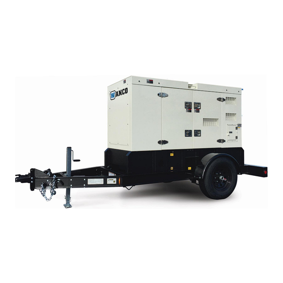
- Page 1 Silent Power Series Generator Operator Manual Model WSP12 with DSE6020 Controller PN: 221235...
- Page 2 Thank you for purchasing a Wanco Silent Power Series three-phase diesel generator set. This manual contains important safety and operating information - please read the complete manual before attempting to operate the generator. All information in this publication is based on the latest product information available at the time of approval for printing.
-
Page 3: Table Of Contents
CONTENTS 1. SAFETY INSTRUCTIONS ..............4 2. QUICK START CHECKLIST ..............6 3. MAJOR COMPONENT LOCATIONS ............. 7 4. OPERATION ..................11 5. MAINTENANCE ..................12 6. FLUIDS & COMMON SERVICE PARTS ..........13 7. TROUBLESHOOTING ................13 8. SPECIFICATIONS ................. 14 9. -
Page 4: Safety Instructions
SAFETY INSTRUCTIONS Electric Shock Hazard. Contact with electric power lines will cause serious injury or death. Contact with AC output terminals or other live electrical circuits on this generator during operation will result in severe injury or death. ... - Page 5 Electric Shock Hazard Disconnect the cranking battery negative terminal and/or disengage the battery at the Battery Disconnect Switch before servicing any part of the engine, alternator or generator controls. Moving Parts Hazard Disconnect the cranking battery negative terminal and/or disengage the battery at the Battery Disconnect Switch before servicing any part of the engine, alternator or generator controls.
-
Page 6: Quick Start Checklist
GENSET QUICK START/STOP CHECKLIST These instructions are for starting the generator set in Manual Mode. Read the entire genset Operator Manual before starting the engine Pre-Startup Checks Check coolant level, oil level and confirm that you have sufficient fuel. Confirm the Fuel Valve is in the correct position for the fuel source (skid tank or external supply). Confirm the Estop button is in Run mode (turn it clockwise to release). -
Page 7: Major Component Locations
MAJOR COMPONENT LOCATIONS Generator left-side view (from operator’s position) Control Panel Emergency Stop Switch Lift Hook Containment Vessel Cleanout & Diesel Tank Drain Forklift Access (2X) Generator right-side view (from operator’s position) Receptacles & Circuit Breakers External Diesel Connections Oil Drain Coolant Drain Page | 7... - Page 8 The Deepsea Genset Controller: Located in the Control Panel at the operator end of the generator. Refer to the DSE6020 Mk II Operators Manual for additional information Start Engine (Manual Menu Navigation Buttons Display Mode only) Stop/Reset Mode Auto Mode Manual Mode Mute Alarm &...
- Page 9 Lower AC Connection Panel Located behind the flip-up panel on the generator right side. Circuit Breakers for 120/240V NEMA L14-30 Main Circuit Breaker Receptacles Receptacle 120V NEMA TT30 RV 120/240V CS6369 120V GFCI Receptacles Receptacle Receptacles Emergency Stop Switch Located outside, beside the AC electrical connection panel on the generator right side.
- Page 10 Main Circuit Breaker Located in the Connection Panel near the receptacles. The Main Circuit Breaker is present to protect the AC alternator windings from overload damage. When the circuit breaker is in the ON position, current can flow from the alternator to the AC output connections. When in the OFF position, no current or voltage will be present at any AC output connection.
-
Page 11: Operation
OPERATING THE GENERATOR Before starting the engine: Check engine oil level Check engine coolant level Confirm that sufficient fuel is in the fuel tank Confirm that the Emergency Stop Button is not depressed (rotate clockwise to release) ... -
Page 12: Maintenance
MAINTENANCE Engine Service Schedule Refer to Perkins SEBU8609 Operation Manual for additional information and for service intervals beyond than 1000hrs. Frequency Task Daily Check coolant Inspect air cleaner service indicator Check oil level, add as needed Drain water from primary fuel/water separator Visual inspection for leaks, loose parts, etc. -
Page 13: Fluids & Common Service Parts
ENGINE FLUIDS & COMMON SERVICE PARTS Fuel D1/D2 Diesel, minimum cetane 40, ULSD Coolant Ethylene glycol meeting ASTM D4985, mixed 1:1 with water Air filter element 135326205 Fuel pre-filter None Fuel filter 26561117 Oil filter 140517050 API CH-4 or higher, or EMA DHD-1. Mineral or synthetic base: Engine oil SAE 0W40 −40 °C (−40 °F) 40 °C (104 °F) SAE 10W30 −20 °C (−4 °F) 40 °C (104 °F) -
Page 14: Specifications
Voltage Regulator Mecc Alte DSR Excitation Boost Mecc Alte MAUX Dimensions L x W x H 72 in L x 32 in W x 51 in H Weight dry w/o trailer 1650 lb * Wanco trailer available Page | 14... -
Page 15: Wiring Diagram
WIRING DIAGRAM Page | 15... -
Page 16: Towing
TOWING Check tires, wheels, and axle lock: Failure to properly follow these precautions can result in property damage, serious injury or death Check tires for wear. Replace worn tires. Ensure tires are inflated to the proper pressure. Verify all wheel lugs are in place and tightened. Do not tow the trailer if a wheel lug is missing. Check the drawbar, tow hitch, and safety chains: Failure to properly follow these precautions can result in property damage, serious injury or death... - Page 17 Raise, rotate, and lock the drawbar jack in the up or horizontal position. Verify approved safety chains are attached properly to both the trailer and tow vehicle. The chains should cross underneath the tow hitch. Ensure the trailer brake lights, taillights, and directional (turn) indicators are connected and functioning properly.
- Page 18 After towing After towing, unhook the tow chains from the tow vehicle, then use the drawbar-mounted jack to raise the drawbar and release the drawbar hitch from the tow vehicle. Pull the vehicle away from the message sign trailer when ready. Page | 18...
Need help?
Do you have a question about the WSP12 and is the answer not in the manual?
Questions and answers