
Related Manuals for Sierra Mass-Trak 810M


Summary of Contents for Sierra Mass-Trak 810M
- Page 1 Sierra 810 Series Mass-Trak ® Mass Flow Instruments Instruction Manual Part Number: IM-81 Revision H 4/15...
- Page 2 Sierra Instruments, Inc. is not liable for any damage or personal injury, whatsoever, resulting from the use of Sierra Instruments standard mass flow meters or controllers for oxygen gas. You are responsible for determining if this mass flow meter or controller is appropriate for your oxygen application.
-
Page 3: Table Of Contents
Series 810 Table of Contents TABLE OF CONTENTS Chapter 1 Introduction Introduction ..........Using this Manual ........Safety Information ....... Receipt of System Components ..Technical Assistance ......The 810 Series Flow Sensing Principle Chapter 2 Installation Installation Overview ........Before Beginni n g an Installati o n........ - Page 4 Table of Contents Series 810 Appendix A Conversion Formulas and Gas Tables Appendix B Product Specifications & Mounting Appendix C Pin Connections Appendix D Purge and Valve Off Connections Appendix E Warranty Policy List of Figures 1-1. Mass-Trak Features (Typical) ....... 1-2.
-
Page 5: Chapter 1 Introduction
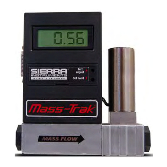
This instruction manual covers the installation, operation and maintenance of the Mass-Trak product line, which includes the following Sierra models: Model 810M Mass-Trak Flow Meter... -
Page 6: Using This Manual
Appendix D describes the purge and valve off connections Appendix E details the warranty policy for the product Throughout this manual, we use the word transducer as a generic term to represent all models of Sierra's 810 Series Mass-Trak instruments. IM-81... -
Page 7: Safety Information
If the problem persists after following the troubleshooting procedures outlined in Chapter 5, contact Sierra Instruments by fax or by E-mail (see inside front cover). For urgent phone support you may call (800) 866-0200 or (831) 373-0200 between 8:00 a.m. and 5:00 p.m. PST. -
Page 8: Flow Paths Through The Transducer
Chapter 1 Introduction Series 810 Instruction Manual The 810 Mass -Trak Flow Sensing Principle The operating principle of Mass-Trak transducers is based on heat transfer and the first law of thermodynamics. During operation process gas enters the instrument's flow body, where it encounters the laminar flow bypass. - Page 9 For mass flow controllers, once the gas flows through the monitoring section, it is then controlled by the built-in servo-control valve. All models of the Mass-Trak utilize Sierra's proprietary high- efficiency Fast-Trak Electromagnetic Valve. The normally closed Fast-Trak valve is similar to an on/off solenoid valve, except that the...
-
Page 10: Chapter 2 Installation Installation Overview
Series 810 Instruction Manual Chapter 2 Installation Chapter 2 Installation Installation Overview Mass-Trak transducers are supplied with female NPT, compression, VCO, or VCR process connections. To ensure a successful installation, inlet and outlet tubing should be in a clean state prior to plumbing the transducer into the system. -
Page 11: Installing The Transducer-Plumbing
Chapter 2 Installation Series 810 Instruction Manual 1 %). Using the output that is recorded on the data tag will optimize instrument performance. 8. Integral Display: The 3 1/2 digit LCD display reads directly in engineering units or percent of full scale. The full-scale range and gas are shown on the instrument data tag. -
Page 12: Vco Fittings
Series 810 Instruction Manual Chapter 2 Installation Check the system's entire flow path thoroughly for leaks. (Do not use liquid leak detectors. Instead, monitor pressure decay. Exposing the transducer to leak detector fluid may damage the unit.) VCO Fittings 1. Position the transducer with the flow direction arrow pointing in the direction of flow. -
Page 13: Installing The Transducer (Electrical)
Chapter 2 Installation Series 810 Instruction Manual IMPORTANT—Straight-run requirement (critical for nylon flow body instruments Install a section of straight pipe at least five pipe diameters in length upstream of the transducer. DO NOT use reducers. In the case of a flow meter, at least two pipe diameters downstream are required for optimum performance. -
Page 14: D-Connector Pin Assignments
Series 810 Instruction Manual Chapter 2 Installation Figure 2-2. Transducer D-Connector Pin Assignments IM-81... -
Page 15: Chapter 3 Operation
After the transducer is installed and the system has undergone a complete leak check, follow these steps: 1. Apply power to your Mass-Trak using Sierra's power supply or your own input power source. When power is first applied, the output signal will remain at a high level until the sensor reaches its normal operating temperature range. -
Page 16: Setpoint Adjustment
(The valve will open momentarily when power is first applied). 2. Apply power to your Mass-Trak using Sierra's power supply or your own input power. When power is first applied, the output signal will remain at a high level until the sensor reaches its normal operating temperature range. -
Page 17: Setpoint Configuration
Series 810 Instruction Manual Chapter 3 Operation Figure 3-1 Component Location and DIP Switch Set-up of Mass-Trak Setpoint Configuration (see Figure 3 -1 The DIP switches located behind the front panel on the Mass-Trak flow controllers are used to configure setpoint operation and the Automatic Shut- Off feature. -
Page 18: Over-Range Condition
Chapter 3 Operation Series 810 Instruction Manual A 5.1 VDC reference is provided for internal and external setpoint command pots. The reference provides approximately 0.125 volts headroom to allow for external cabling and ensures that the instrument will always reach full scale when using these inputs. DIP switch 6 has no function at this time. -
Page 19: Auto Shut-Off Function
Series 810 Instruction Manual Chapter 3 Operation 4. Sensor failure. The cold sensor lockout circuit is enabled during initial start-up. Its operation may be checked by observing the output signal or the LCD display (on models so equipped). The output signal or display will read high for the first 10 to 20 seconds. - Page 20 Chapter 3 Operation Series 810 Instruction Manual Purging Non-Reactive Gases: Purge the transducer with clean, dry nitrogen for a minimum of two hours. Purging Reactive Gases: One of the following methods may be used: Cycle purge. This is done by alternately evacuating and purging the transducer for 2 to 4 hours with clean, dry Caution! nitrogen.
-
Page 21: Chapter 4 Maintenance
If the screen appears corroded or damaged it will Caution) need to be replaced. Contact the Sierra Instruments Customer Service Do not disassemble the Department before removing the fittings or the screen, as it is possible to... -
Page 22: Nylon Transducer Internals
Chapter 4 Maintenance Series 810 Instruction Manual Figure 4-1. Stainless Steel Low Flow Transducer Internals Figure 4-2. Stainless Steel Medium Flow Transducer Internals Caution! Do not remove the sensor cover, this could shift Figure 4-3 Nylon Transducer Internals transducer calibration. Sensor Maintenance The sensor tube is straight and has a relatively large, 0.031 inch ID. -
Page 23: Valve Maintenance
Chapter 4 Maintenance Sensor Inspection and Cleaning Cleaning is accomplished by simply rodding out the sensor with the Sensor Cleaning Stylette, available from Sierra for this purpose. To access the sensor for inspection or cleaning: Caution! Remove the instrument from the When using toxic or system. -
Page 24: Valve Adjustment Procedure
Chapter 4 Maintenance Series 810 Instruction Manual Valve Adjustment Mass-Trak controls flow with a proportional electromagnetic valve that is set up for certain process operation conditions. Variables that affect its operation include orifice size, spring selection and adjustment, and input and output pressures. If operating conditions change it may be necessary to make a valve spring adjustment. -
Page 25: Transducer Calibration
If these adjustments do not restore proper performance to your Mass-Trak, this transducer. contact Sierra Instruments' Technical Support Department. Transducer Calibration Calibration of Sierra's flow meters and controllers requires a calibration standard of at least equal accuracy and preferably an order of magnitude IM-81... - Page 26 All measuring and test equipment used in the calibration of Sierra transducers is traceable to NIST standards. Sierra is ISO-9001 registered and conforms to the requirements of ANSI/NCSL-Z540 and ISO/IEC Guide 25. If your instrument has been damaged or you simply want to have the transducer re- calibrated, see Chapter 5 or contact the factory for return shipping instructions.
-
Page 27: Chapter 5 Troubleshooting
Series 810 Instruction Manual Chapter 5 Troubleshooting and Service Chapter 5 Transducer Troubleshooting When you suspect that the transducer is not operating correctly, there are a few simple checks that can be made before taking the unit out of service: 1. - Page 28 Chapter 5 Troubleshooting and Service Series 810 Instruction Manual Low or no gas pressure Set correct gas pressure Controller does not respond to set point Faulty cable or connector Correct or replace Increase set point or disable auto Set point is below 2% of full scale shut off circuit DIP switches improperly set Re-configure DIP switches...
-
Page 29: Returning Equipment To The Factory
Factory Calibration—All Models Sierra Instruments maintains a fully-equipped calibration laboratory. All measuring and test equipment used in the calibration of Sierra transducers are traceable to NIST Standards. Sierra is ISO-9001 registered and conforms to the requirements of ANSI/NCSL-Z540 and ISO/IEC Guide 25. -
Page 30: Appendix A Conversion Formulas And Gas Tables
Series 810 Instruction Manual Appendix A Appendix A Conversion Formulas and Gas Tables Calculations for Use with a Pure Gas The following tables provide K-factors and thermodynamic properties of gases commonly used with mass flow meters and controllers. The purpose of these tables is two-fold: 1. - Page 31 The value from the tables is preferred because in many cases it was obtained by experiment. Sierra calibrates every transducer with primary standards using the actual gas or a molecular equivalent reference gas.
- Page 32 Series 810 Instruction Manual Appendix A Example 1: A transducer is calibrated for nitrogen (N ), and the flow rate is 1000 sccm for a 5.000 VDC output signal. The flow rate for carbon dioxide at a 5.000 VDC output is: , or = (0.74/1.000)1000 = 740 sccm Example 2:...
- Page 33 Appendix A Series 810 Instruction Manual The equivalency relationships for p , C , and N for mixtures of more than two gases have a form similar to the dual-gas relationship given above. IMPORTANT NOTE ABOUT K-FACTORS: Please note that if you have a transducer calibrated for a gas such as methane and wish to use the K-factors to measure a gas such as air, the inaccuracy of the measurement can range from ±5 to 10%.
- Page 34 Series 810 Instruction Manual Appendix A Gas Tables and K-factors Actual Gas Elastomer* O- K-factor Density Chemical Nylon ring Valve Relative (g/l) @ Symbol (Cal/g) Compatible Seat 0°C .4036 1.162 Acetylene 1.00 .240 1.293 Allene (Propadiene) .352 1.787 Ammonia .492 .760 Argon 1.45...
- Page 35 Appendix A Series 810 Instruction Manual K-factor Density Elastomer* O- Chemical Nylon ring Valve Symbol Relative (Cal/g) (g/l) @ Compatible Actual Gas Seat 0°C .1882 5.758 SiCL Dichloromethylsilane Dichlorosilane .150 4.506 .1604 7.626 (Freon-114) 1,1-Di uoroethylene .224 2.857 (Freon-1132A) .366 2.011 Dimethylamine .3414...
- Page 36 Series 810 Instruction Manual Appendix A Actual Gas Elastomer* O- Chemical K-factor Density Nylon Symbol Relative (Cal/g) (g/l) @ ring Valve Compatible 0°C Seat .2459 2.146 Methyl Mercaptan Methyl Trichlorosilane ) SiCl .164 6.669 Molybdenum Hexafluoride .1373 9.366 Monoethylamine .387 2.011 Monomethylamine .4343...
-
Page 37: Appendix B Product Specifications & Mounting
Series 810 Instruction Manual Appendix B Specifications & Mounting Instructions Appendix B Product Specifications & Mounting IM-81... - Page 38 Appendix B Specifications & Mounting Instructions Series 810 Instruction Manual IM-81...
- Page 39 Series 810 Instruction Manual Appendix B Specifications & Mounting Instructions Transducer Mounting Dimensions All dimensions are inches, millimeters are in parentheses. Certified drawings are available on request. Nylon Flow Body Mount the Mass-Trak to a chassis with two #6, type “B” self-tapping screws. CAUTION: These screws should extend into the flow body no further than .15”...
-
Page 40: Appendix C Pin Connections
Series 810 Appendix C Pin Connection Appendix C Pin Connections IM-81... -
Page 41: Appendix D Purge And Valve Off Connections
LIMITED WARRANTY POLICY- REGISTER ONLINE All Sierra products are warranted to be free from defects in material and workmanship and will be repaired or replaced at no charge to Buyer, provided return or rejection of product is made within a reasonable period but no longer than one (1) year for calibration and non-calibration defects, from date of delivery.
Need help?
Do you have a question about the Mass-Trak 810M and is the answer not in the manual?
Questions and answers