
Related Manuals for Sierra M50L-AL


Summary of Contents for Sierra M50L-AL
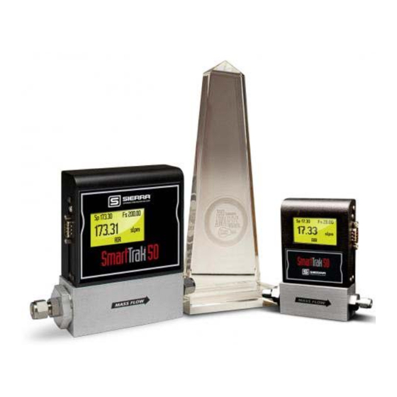
- Page 1 Instruction Manual SmartTrak 50 Series ® SmartTrak 50 Series ® Economical/OEM Digital Gas Mass Flow Control up to 200 slpm (nlpm) Instruction Manual IM-50, Rev. I, June 2017 IM-50...
- Page 2 IMPORTANT CUSTOMER NOTICE: OXYGEN SERVICE Sierra Instruments, Inc. is not liable for any damage or personal injury, whatsoever, resulting from the use of Sierra Instruments standard mass flow meters or controllers for oxygen gas. You are responsible for determining if this mass flow meter or controller is appropriate for your oxygen application.
-
Page 3: Table Of Contents
Instruction Manual SmartTrak 50 Series ® Table of Contents Chapter 1: Introduction ..........................4 Chapter 2: Installation ..........................9 Before You Begin Installation ........................9 Installing the Instrument—Plumbing ....................... 10 Compression Fittings ........................10 VCO Fittings .......................... -
Page 4: Chapter 1: Introduction
SmartTrak 50 Series ® Chapter 1: Introduction ® This instruction manual is your guide to the SmartTrak 50 Series. Visit the Sierra Instruments website www.sierrainstruments.com/products/50series.html for more information about this product. Using This Manual This manual is organized into five chapters: ... - Page 5 Make sure any spare parts or accessories are not discarded with the packing material. Do not return any equipment to the factory without first contacting one of Sierra’s Technical Support Centers: USA (Headquarters) Customer Service:...
- Page 6 Instruction Manual SmartTrak 50 Series ® Definitions Used In This Manual The following terms are used frequently in this manual. They are presented here with their definitions for your information. Setpoint—The command or control signal supplied to a flow controller is called the setpoint.
- Page 7 Instruction Manual SmartTrak 50 Series ® The SmartTrak 50 Series Flow Sensing Principle ® ® The operating principle of the SmartTrak 50 Series instruments is based upon heat transfer and the first law of thermodynamics. During operation process gas enters the instrument’s flow body and divides into two flow paths, one through the sensor tube and the other through the laminar flow bypass.
- Page 8 Instruction Manual SmartTrak 50 Series ® Figure 1-3. Sensor Temperature Distribution Figures 1-2 and 1-3 show the mass flow through the sensor tube as inversely proportional to the temperature difference of the coils. The coils are legs of a bridge circuit with an output voltage in direct proportion to the difference in the coils’...
-
Page 9: Chapter 2: Installation
Recommended filter size: 10 micron. A 10 micron filter will eliminate the possibility of sensor tube clogs, maximizing the life of the unit and accuracy of the calibration. A 10 micron filter is available from Sierra as an accessory. See Appendix B or contact your local Sierra distributor. -
Page 10: Installing The Instrument-Plumbing
Instruction Manual SmartTrak 50 Series ® 5. Output Signals: The 50 Series has RS-232 communications as the standard configuration, with optional RS-485, 0-5 VDC or 4-20 mA. The output signals specified at time of order will be indicated on the data label. 6. -
Page 11: Vco Fittings
Instruction Manual SmartTrak 50 Series ® VCO Fittings Position the instrument with the flow direction arrow pointing in the direction of flow. Tighten the nut finger-tight, and then 1/8 turn tighter with a wrench. Do not over- tighten! Check the system’s entire flow path thoroughly for leaks. Do not use liquid leak detectors on or near the unit. -
Page 12: Installing Your Instrument-Mechanical Mounting
Instruction Manual SmartTrak 50 Series ® Installing Your Instrument—Mechanical Mounting Mounting Your Instrument The base plate or bottom of the instrument has four mounting holes. Two are SAE thread and two are metric thread. For location and dimensions, please see Appendix B. Installing Your Instrument—Electrical Connections ®... -
Page 13: Instrument Power
If the instrument will be used without permanent mounting (on a laboratory bench, for instance) then connect the shield wire (no insulation) to earth ground in your facility. If you purchased a Sierra power supply, a ground wire is provided for your convenience. - Page 14 To minimize the potential for RF interference, it is recommended to shield these wires. If you are making your own cabling, Sierra recommends you use wire that comes shielded. Solder one end of the shield wire/casing to the DB-9 connector at one end of the wire, so as to allow the collected interference to dump to earth ground.
-
Page 15: Chapter 3: Digital Operation
TAKE NECESSARY PRECAUTIONS. 2. Power Up Your Instrument: Apply power to your instrument using Sierra’s power supply or your own input power source. See Chapter 2, Figure 2-2: After a few seconds of warm up the display (Optional) will turn on. -
Page 16: Loading The Smarttrak ® 50 Series Software
50 Series to Your Computer ® We suggest you use the Sierra Instruments RS-232 communication cable (part number C9RS232). This pre-manufactured cable has the correct DB9 connection to mate with all computer DB9 serial ports, and a DB9 to connect to the instrument. - Page 17 PC to handle the load. If connecting your computer to the SmartTrak ® 50 Series creates any confusion, please contact Sierra Instruments or your IT person for assistance. Running the SmartTrak 50 Series User Software ®...
- Page 18 Instruction Manual SmartTrak 50 Series ® You will see the following main screen: NOTE: Hovering the mouse pointer over any of the input fields and buttons will give you a description of its purpose. 2. Select ComPort in the menu to set up the ComPort. (See below) IM-50...
- Page 19 Instruction Manual SmartTrak 50 Series ® 3. Select the ComPort pull down menu shown As shown above, use the pull-down menu to choose the port number that corresponds to the serial port channel your 50 Series is connected to. Depending on whether the unit is RS-232 or RS-485, you’ll need to select the proper “ASCII Commands”...
- Page 20 Instruction Manual SmartTrak 50 Series ® 4. Close the window using the X button in the upper right corner of the dialog box. The communications are set up, and the unit should be communicating with the computer, as evident by the changing numbers right of the COM1: port in the picture below. If the numbers are not changing, click ‘Get Parameters.’...
- Page 21 Instruction Manual SmartTrak 50 Series ® Important Features of the SmartTrak 50 Series User Software ® You can learn more about your unit, including the Serial Number, Firmware Version, etc., by clicking on the ‘Info’ button. The final window below will provide control of the system. Click the ‘Adjustments’ button.
- Page 22 Instruction Manual SmartTrak 50 Series ® Hovering the mouse pointer over the input fields and buttons listed above will give you a description of its purpose. For your reference, this is shown below. IM-50...
- Page 23 Instruction Manual SmartTrak 50 Series ® Change the value in any input field by selecting the data and inputting a desired value. Below left, for example, we have selected Setpoint. Below right, we have entered 1.234 IM-50...
- Page 24 Instruction Manual SmartTrak 50 Series ® Select ‘Enter’ on your computer keyboard to confirm. The value will change from RED to BLACK. IM-50...
- Page 25 The Setpoint box displays the current setpoint given to the flow controller in the ‘Adjustments’ window, the engineering units, the source of the setpoint signal, the dac values for the valve (for Sierra troubleshooting only). Full Scale The box displays the full scale flow rate, the engineering units, the Com Port selected, and communications count.
-
Page 26: Chapter 4: Analog Operation
Power Your Instrument: Provide adequate power per Figure 2-2. Apply power using Sierra’s power supply or your own power source. Hook up the analog output per Figure 2-2 if desired, or use the RS communications or display (optional) to read mass flow value. Let the instrument warm up for at least 15 minutes for optimal performance. - Page 27 Instruction Manual SmartTrak 50 Series ® 3. Adjust the controller setpoint to the desired flow rate by supplying an appropriate signal (mA, voltage or digital). The effective control range of the unit is 5% to 100% of the calibrated full scale flow range. Automatic shut-off occurs at 4.9% of the factory full scale calibrated range unless specifically modified at time of order.
-
Page 28: Setpoint Adjustment
Instruction Manual SmartTrak 50 Series ® 50 Series Features Setpoint Adjustment The setpoint (command) input signal you supply to the 50 Series must be a direct linear representation of 0% to 100% of the mass flow full scale value. Apply the setpoint signal per Chapter 2. -
Page 29: Over-Range Condition
Instruction Manual SmartTrak 50 Series ® CAUTION! Note: Zero-button needs only a light touch to activate. Pay attention for a physical click feeling and/ or a very quiet, but audible *click* noise. DO NOT push hard! There is no reason to hold the button down, either. If you push too hard the plastic button may become stuck under the edge of the metal shroud that holds it. -
Page 30: Chapter 5: Technical Support & Service
Verify that your settings and adjustments are consistent with factory recommendations. If the problem persists, Sierra is eager to help you. You may contact us at any of the following Technical Support Centers listed below. It may also help to call your Sierra Sales Agent, who is also well trained in the operation of the product. - Page 31 Factory Calibration—All Models Sierra Instruments maintains a fully-equipped calibration laboratory. All measuring and test equipment used in the calibration of Sierra transducers are traceable to NIST Standards. Sierra is ISO-9001 registered and conforms to the requirements of ANSI/NCSL-Z540 and ISO/IEC Guide 25.
- Page 32 Pack your instrument carefully. Use the original packaging and foam or bubble wrap (packing peanuts NOT recommended) and include a copy of the RMA form (complete with Sierra supplied RMA number) with the unit(s). Ship the unit(s) to the following address: Sierra Instruments, Inc.
-
Page 33: Appendix A: Gas Tables & K-Factor Calculations
Instruction Manual SmartTrak 50 Series ® Appendix A: Gas Tables & K-Factor Calculations K-Factor Calculations-- Using SmartTrak ® 50 Series with Other Gases ® If you will be using SmartTrak 50 Series with a gas other than as calibrated, you may use the tables below. - Page 34 Instruction Manual SmartTrak 50 Series ® Gas Tables and K-factors Chemical K-factor Density Density Elastomers* Actual Gas Symbol Relative (Cal/g) (g/l) @ (g/l) @ O-ring Valve to Air 70°F 0°C Seat Acetylene .581 .4036 1.079 1.162 1.000 .240 1.200 1.293 Allene (Propadiene) .431 .352...
- Page 35 Instruction Manual SmartTrak 50 Series ® Actual Gas Chemical K-factor Density Density Elastomers* Symbol Relative (Cal/g) (g/l) @ (g/l) @ O-ring Valve 70°F 0°C Seat Dichloromethylsilane .251 .1882 5.345 5.758 SiCl Dichlorosilane .401 .150 4.183 4.506 Dichlorotetrafluoroethane .220 .1604 7.079 7.626 (Freon-114) 1,1-Difluoroethylene...
- Page 36 Instruction Manual SmartTrak 50 Series ® Chemical K-factor Density Density Elastomers* Actual Gas Symbol Relative (Cal/g) (g/l) @ (g/l) @ O-ring Valve 70°F 0°C Seat Methyl Mercaptan .521 .2459 1.992 2.146 Methyl Trichlorosilane ) SiCl .251 .164 6.191 6.669 Molybdenum Hexafluoride .210 .1373 8.695...
-
Page 37: Appendix B1: 50 Low Flow (To 50 Slpm) Product Specifications
Instruction Manual SmartTrak 50 Series ® Appendix B1: 50 Low Flow (to 50 slpm) Product Specifications IM-50... - Page 38 Instruction Manual SmartTrak 50 Series ® IM-50...
- Page 39 Instruction Manual SmartTrak 50 Series ® IM-50...
-
Page 40: Appendix B2: 50 Medium Flow (To 200 Slpm) Product Specifications
Appendix B2: 50 Medium Flow (to 200 slpm) Product Specifications IM-50... - Page 41 IM-50...
- Page 42 IM-50...
-
Page 43: Appendix C: Warranty Policy
Appendix C: Warranty Policy LIMITED WARRANTY POLICY- REGISTER ONLINE All Sierra products are warranted to be free from defects in material and workmanship and will be repaired or replaced at no charge to Buyer, provided return or rejection of product is made within a reasonable period but no longer than one (1) year for calibration and non-calibration defects, from date of delivery.
Need help?
Do you have a question about the M50L-AL and is the answer not in the manual?
Questions and answers