Table of Contents
Advertisement
Quick Links
DESCRIPTION AND OPERATION
The HB-480R2-x occupancy sensors turn lighting on and off based on
occupancy. They are designed for warehouse and high bay applications.
Careful consideration must be given to sensor placement. Avoid placing the
sensor where shelving or other obstructions may block the sensor's line of
sight.
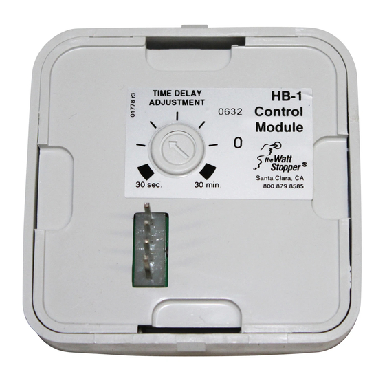
The HB sensors are modular and are made up of two parts, a Power Module
(HB-480R2) and a Control Module (HB-x). The HB-480R2 operates at 480VAC
or 347VAC, 60 Hz.
COVERAGE
Coverage patterns, density and range, are determined by the type of Control
Module attached to the HB-480R2.
For a complete description of each Control Module's coverage pattern, see
the HB-x Control Module COVERAGE GUIDE.
MOUNTING THE SENSOR
Junction Box
CP-1 J-Box
Adapter
Plate
HB-480R2
Power Module
Control Module
(HB-2 shown)
Fig 1:
Ceiling Mount Assembly
IMPORTANT START-UP INFORMATION
When the control module is installed and power is connected, it may take up
to a minute before the lights turn on due to a sensor warm-up period required
during initial power-up. This occurs during installation or after a power failure
of 5 minutes or more only.
If the power module is installed and powered, and no control module is in
place, the load comes on and remains on until the control module is installed.
Fixture
Fig 2:
Fixture Mount Assembly
H B - 4 8 0 R 2 - x *
High Bay • Line Vo l tage • Pa ss i ve Infra red
O ccupancy Sensor Power Module
SPECIFICATIONS
HB-480R2 Power Module
Voltages . . . . . . . . . . . . . . . . . . . . . . . . . .347/480VAC, 60Hz
Load Requirements
@ 480VAC, 60Hz . . . . . . . . . . . . . . . . . . .1200W ballast
@ 347VAC, 60Hz . . . . . . . . . . . . . . . . . . .1200W ballast
US Patents: . . . . . . . . . .4,787,722 • 4,874,962 • 5,124,566
* x indicates Control Module/Lens number. See Coverage Guide.
INSTALLATION
CAUTION
TURN THE POWER OFF AT THE CIRCUIT
BREAKER BEFORE INSTALLING THE SENSOR.
1.
Connect the existing wires to the sensor
leads.
• Do not allow bare wire to show.
• Make sure all connections are secure.
2.
Remove the Control Module from the
HB-480R2 as shown in Fig. 7.
3a. Ceiling Mount (See Fig. 1):
• Secure the CP-1 J-Box adapter plate
to the junction box.
• Attach the sensor to the adapter plate
3
using four #6 x
/
" self tapping screws.
4
3b. Acoustic Tile or Fixture (See Fig. 2):
• Cut a hole in the mounting surface
using the "HB Cut-Out" template.
3
• Use four #6 x
/
" self tapping screws
4
to attach the sensor to the mounting
surface.
4.
Reconnect the Control Module onto the
HB-480R2 as shown in Fig. 4.
• CAREFULLY align the four connector
pins on the HB-480R2 with the
receptacles on the Control Module.
• Snap the HB-480R2 Power Module to
the Control Module using firm pressure
until they click into position at the top
and bottom.
5.
Restore power from the circuit breaker.
WIRING
Fig 5: 4 8 0 VAC wiring
Fig 6: 3 4 7 VAC wiring
Fig 3:
Flying lead
c o n n e c t i o n s
Fig 4:
Connecting the
C o n t rol Module to the
H B-480R2 Power Module.
Advertisement
Table of Contents

Related Manuals for wattstopper HB Series

Summary of Contents for wattstopper HB Series
- Page 1 H B - 4 8 0 R 2 - x * High Bay • Line Vo l tage • Pa ss i ve Infra red O ccupancy Sensor Power Module SPECIFICATIONS DESCRIPTION AND OPERATION HB-480R2 Power Module The HB-480R2-x occupancy sensors turn lighting on and off based on occupancy.
- Page 2 4. Check sensor wire connections. Verify load and neutral wires are secure. 2800 De La Cruz Boulevard, Santa Clara, CA 95050 Technical Support: 800.879.8585 • 972.578.1699 www.wattstopper.com Visit our website for FAQs: www.wattstopper.com 04407r3 7/2005...
Need help?
Do you have a question about the HB Series and is the answer not in the manual?
Questions and answers