Table of Contents
Advertisement
Advertisement
Table of Contents

Subscribe to Our Youtube Channel
Related Manuals for KickAss KAMPPTRC


Summary of Contents for KickAss KAMPPTRC
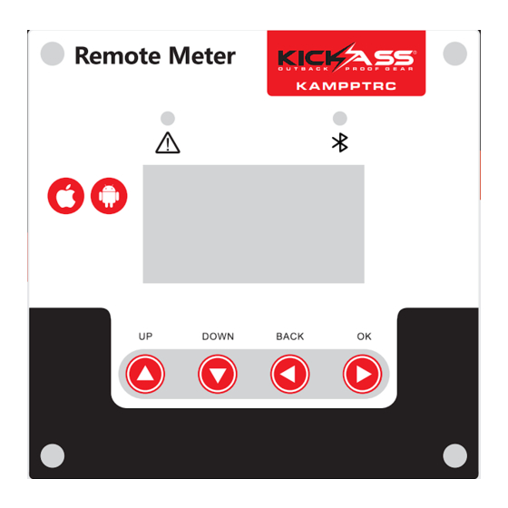
- Page 1 REMOTE METER USER MANUAL K A M P P T R C KAMPPTRC...
-
Page 2: Product Features
1) carefully read all instructions and precautions in this manual to insure correct use of controller. 2) This controller is only to be used with the KickAss mppt regulator. 3) The data displayed on the controller will update every 3 seconds. -
Page 3: Installation Instructions
5. INSTALLATION INSTRUCTIONS Installation on a controller case or panel External dimensions: 115.82×115.82mm Installation dimensions: 96mm or 103.82x103.82mm Installation hole diameter: ¢3.5 (mm) Right view Front 5.2、Installation on a wall External dimensions: 118.5×118.5×48mm Installation dimensions: 50×50mm or 70×70mm Installation hole diameter: ¢5(mm) -
Page 4: Parameter Details
6. DATA CABLE DEFINITION Controller communication port RJ12 and the core series number is as follows: Definition ① Receiving terminal RX ① ② ③ ④ ⑤ ⑥ ② Transmitting terminal TX ③ Power supply grounding/ signal grounding ④ Power supply grounding/ signal grounding Power supply positive ⑤... -
Page 5: Solar Controller
9. FAULT INDICATION AND COMMUNICATION INDICATION Communication connection indicator Communication fault indicator K A M P P T R C Indicator State Description Steady off The controller system is normal System fault indicator Abnormality occurs to the controller system(Please check Quick flashing the error code) Communication connection between the LCD display unit... - Page 6 10.1 Menu block diagram Real-time Main menu monitoring Load mode Parameters setting Statistic data Historical data of the current day Device information Bluetooth connection state (This menu is available only to the display units with the optional bluetooth function) Refer to "Usage of Navigation Keys" for operations including entering into and exiting each of the above menus, related parameters setting, etc.
- Page 7 10.2 Main menu Battery icon and SOC Load current icon Charging current icon Day or night indicating icon Load icon and state indication 26.8V 11.6V Load state Solar panel voltage charging power load current charging current Battery voltage Definitions of "main menu" icons State Description Icon or value...
-
Page 8: Parameter Settings
10.3 Parameter Settings Parameter settings list Displayed item/ Menu level Page Item to set Parameter and setting range Remarks parameter “ 12V ”12V system “24V ”24V system Battery system BatSysVol : “36V ”36V system voltage “ 48V ”48V system “ AUTO” auto recognition “SLD”sealed lead-acid battery “FLD”... - Page 9 10.4.1 Controller Charging And Discharging Related Parameters 1) All voltage values are based on 12 volt system settings. For example for a 24 volt system most parameter setting will need to be doubled. 2) Tap the up or down key to select parameter to be set then tap the right arrow button and the parameter or sign will flash continue to tap the up or down button then tap the ok button again to confirm setting.
-
Page 10: Static Data
10.5 Load Modes Load mode setting icon Load state <Mode> Manual Load mode LOAD 1) If the characters above the “<mode>” are on, it indicates that the load is switched on and off indicates it is switched off 2) Tap the ok key to enter into load setting parameter and below the “<mode>” the display will flash use the up down keys to select any of the load modes then tap ok to confirm setting. - Page 11 Menu level Page Displayed item/ parameter Description C-chg: Total charging amp-hrs C-lod: Total discharging amp-hrs Total power generation E-chg: 0KWH 2nd-level Total power consumption E-lod: 0KWH menus Total number of operating days Rundays : 10D LVD-Count : 0 Total number of over-discharges Total number of full-charges FUL-Count :...
-
Page 12: Common Problems And Solutions
10.8 Device information Device information icon 4845 Product model Ver: 00.00.04 Software version Product serial number INFO SN: 16030032 Description Page Menu level Item Model : Controller model 4845 Hardware version HW-ver: 00.02.07 2st-level menu Software version SW-ver: 00.00.04 Controller serial number Serial:...
Need help?
Do you have a question about the KAMPPTRC and is the answer not in the manual?
Questions and answers